| Last additions - bbyer's Gallery |

D pillar speaker cover removed to facilitate removal of the bin cover.11 viewsThe pipe thing exposed when the D pillar cover is removed is something to do with the side curtain air bags and hence is not to be disturbed - at least my me. Removal of the cover make lifting of the bin cover easier.13 Sep 2024
|
|

Ford Sounder 4L1Z-15K864 A that I installed.12 viewsThis is the Ford sounder, part number 4L1Z-15K864 that I purchased and installed in lieu of the official Land Rover sounder. Note the part number is what is printed on the box (and also my invoice) but the part number on the sounder body is a bit different. I think a new box/invoice related part number is created each time the price of a part is changed. Regardless the Ford sounder was about half the cost of the Land Rover part and sounds the same as the removed factory buzzer.13 Sep 2024
|
|

Land Rover LR006482 replacement sounder10 viewsThis is the official Land Rover replacement sounder, part number LR006482 and costs about double the Ford part number sounder. I used the Ford sounder and it sounds the same as the original factory sounder in my 2005 LR3.13 Sep 2024
|
|
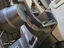
Bin Cover removed showing forward release clips that clip into the two rectangular slots.10 viewsOne has to pull up on the Bin Cover to unlatch the two metal clips, hence why release of the C pillar cover makes the bin cover removal and reinstall easier.13 Sep 2024
|
|
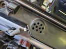
Buzzer located under black plastic cover.12 viewsThe white electrical connector clicks into the buzzer housing that is shown protruding from under the black plastic cover. There is a little tab on the white plastic that has to be squeezed to release the connector. In other words, do not pull on the two conductors. 13 Sep 2024
|
|
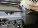
White plastic pin that has to be partly removed to assist in release of buzzer cover.11 viewsThe white coloured plastic pin is located near the C pillar and has to be partly pulled out to release the black plastic buzzer cover.13 Sep 2024
|
|

Bin cover removed to expose plastic moulding covering buzzer.10 viewsI guess this moulding is helping to retain the bin cover when in place rather than to "protect" the buzzer but that is also what it seems to do. In any case, unscrew the two large screws and lift moulding off exposing the buzzer.13 Sep 2024
|
|

C pillar cover removed to facilitate removal of bin cover.9 viewsNote the "ribbon" behind the top left corner of the C pillar cover. This is something to do with the curtain air bags, hence do not mess with it. I dislodged the cover to make it easier to pull up and extract the black plastic bin moulding. It is not necessary to totally remove it and would be what I call a big deal - seat belt, air vent and ducting as well as that curtain concern.13 Sep 2024
|
|

Thread upload3 viewsImage uploaded in thread 12184521 Jan 2024
|
|
Thread upload7 viewsImage uploaded in thread 12184521 Jan 2024
|
|

Thread upload3 viewsImage uploaded in thread 12184521 Jan 2024
|
|

Thread upload42 viewsImage uploaded in thread 4750729 Aug 2022
|
|
Thread upload43 viewsImage uploaded in thread 4750729 Aug 2022
|
|

Gore Tex Oleophobic Membrane Vents82 viewsThese is a link to a Gore website that explains how the Gore Tex material within the breather cap allow pressure to escape (but retains the oil) and allows moisture free air to come back in but excludes free water. 19 Dec 2021
|
|
Thread upload47 viewsImage uploaded in thread 6979114 Oct 2021
|
|
Thread upload39 viewsImage uploaded in thread 6979114 Oct 2021
|
|
Thread upload39 viewsImage uploaded in thread 6979114 Oct 2021
|
|
Thread upload41 viewsImage uploaded in thread 6979114 Oct 2021
|
|
Thread upload40 viewsImage uploaded in thread 6979114 Oct 2021
|
|

Thread upload31 viewsImage uploaded in thread 6979114 Oct 2021
|
|
Thread upload82 viewsImage uploaded in thread 5287918 Aug 2019
|
|
Thread upload54 viewsImage uploaded in thread 5287918 Aug 2019
|
|
Thread upload104 viewsImage uploaded in thread 14644401 Apr 2018
|
|

Front Heater Doors Description and Operation1396 viewsThis 6 page pdf shows with coloured drawings the air flow thru the front heater as well as discusses the operation of the various air flow doors.04 Feb 2018
|
|

Thermostat Housing LR005631538 viewsWhen the time comes to install a new thermostat, consider installing the whole housing instead.
Advantages are the thermostat is correctly installed, (not as simple as it should be); you get all new plastic and that is important, plus a new coolant temperature sensor and also a new heater coolant bypass valve, the secret part no one realizes is also within.
The cost of the whole assembly is not much more than the cost of a factory thermostat and the effort to replace all is not as difficult as it might seem.03 Feb 2018
|
|

Cooling System - Description and Operation 4.0L and 4.4L petrol engines 5 pages1028 viewsThis is a 5 page pdf that provides some insight into how the coolant flows thru all the hoses. Of interest is the paragraph,(page 3/5), that attempts to explain how and why the thermostat is designed to open at different engine operating temperatures - in brief, the reason for the spaghetti tangle of small hoses on the top of the engine.
There is also reference to an engine oil cooler that I gather cools something I think related to a supercharger, if fitted.28 Jan 2018
|
|

Alternator female plug looking down into top373 viewsThis shows the plug connected to the alternator wiring harness looking down into the top of the plug.
The cavity marked 1 is the AS or BATT SENSE and the wire colour most likely has Brown/Green on it.
The cavity marked 2 is the RC or ALT CON and the wire colour most likely has Red/White on it.
The cavity marked 3 is the L1 or ALT MON and the wire colour likely has Green/White on it.
I say "most likely" as the wire colours are not always the same on all vehicles.
Also the terminal 1 conductor destination is more likely C0570-175 rather than per the jpg.
The #3 pin is located closest to the big B+ terminal.13 Dec 2017
|
|
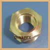
Brass Reducer Adapter M20 x 1.5 male x 1/4" female NPT228 viewsThe brass reducer pictured is an alternative adapter that will also work to go from the metric tank bung thread to the 1/4" NPT.04 Dec 2017
|
|

Pollen Filter Replacement in HVAC System506 viewsThe attached single page doc includes links to pictures of the procedure to replace the "air" filter behind the passenger side glove box related to the Heater AC system.
Part numbers are provided for both Land Rover and Mann filters, both the activated carbon type and the non charcoal filters.18 May 2017
|
|
Thread upload118 viewsImage uploaded in thread 6979103 May 2017
|
|
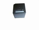
Front Blower R16 relay, part number YWB500060482 viewsThis is the front fan relay located in the engine compartment fuse box. It should be replaced and installed new when a new fan is installed.06 Dec 2016
|
|

Replacing the blower motor578 viewsThis is a 6 page pdf with regards to replacing the HVAC blower fan and the associated fan speed module in a LHD North America spec LR3. The fan can be replaced from below and it is not necessary to pull the dash apart.06 Dec 2016
|
|
Thread upload119 viewsImage uploaded in new thread07 Nov 2016
|
|

ZF 6HP26X-28X Plastic and Metal Pan part numbers and list583 viewsThis 3 page pdf lists the ZF part numbers for the factory metal and plastic pans. Note that the plastic pan is listed as the General pan, and the two metal pans as the BMW and Ford pans. The differences are subtle - drain related it appears.
Torx cap screw descriptions are provided as well as data on the differing gaskets and oil filters.06 May 2016
|
|

Radio Head 6CD-465 Display diagnostics and low power procedure757 viewsThe one page doc outlines the procedure to access the diagnostics for the 6CD-465 entertainment system in most of our LR3's.24 Apr 2016
|
|
Clip Spring Metal FYC 500040 that holds LR together1747 viewsThe jpg is of the spring metal clip, Land Rover part number FYC 500040 that holds most of our 3 together - well at least most the interior trim parts.
If you are going to remove interior panels, you may as well stock up on a few for replacement as upon panel removal, the clips tend to spring away into deep never to be found voids within your 3.23 Apr 2016
|
|

Alarm System description and Operation1052 viewsThis 9 page pdf explains in detail how the anti-thief, (alarm), system is supposed to operate. The system uses the door ajar switches to provide alarm system signals; as such there are few separate contacts related to the alarm system only.
Page 6 of 9 is of particular interest as it describes the trigger log that is accessible with the dealer T4.
23 Apr 2016
|
|
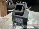
Rhino Tow Loop Hitch270 viewsThis is a receiver end view of the Rhino Hitch that ties to the factory tow loop. In addition to improved strength, it does not reduce ground clearance as does the factory style when installed.
Land Rover in early advertising videos when the 3 first came out showed the D3 hanging from a crane via the frame. The intent was to show how strong the frame is and by inference, the rear tow loop, specifically noted as being good for 6 tonne. The video ends before anything dropped or was lowered back to the ground, so one of course does not know for certain. The Rhino Hitch design however picks up on the apparent evidence of strength and certainly the additional clearance. 06 Mar 2016
|
|

3 Point Hitch on Series 90152 viewsUsually one sees the Series units with just a conventional field plow hooked to a drawbar hitch, tractor style. This jpg however is the full meal deal - a 3 point hitch, probably off a Fordson tractor, in the long tradition of Ford/Land Rover cooperation. 06 Mar 2016
|
|
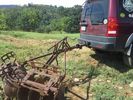
LR3 to plow your garden298 viewsI found this jpg where a current LR owner is using his LR3 for a similar purpose as the original Series units were designed to do - that is serve as a tractor for plowing a field or I suppose a garden.
In this case, I note the hitch is one of those that attach to the factory tow loop, (Rhino Hitch), rather than the factory product that inserts from the bottom and hangs down - (like a plow), but all the time. One of the other jpg's in this album shows the two factory variations plus a third jpg shows a closeup of the Rhino Hitch.06 Mar 2016
|
|
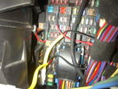
Fuse Panel showing F35P Add A Circuit installed1241 viewsFive amp fuse F35P is located towards the top left in this jpg. The other three Add A Circuit devices are for other items - powering my cell phone base etc.
Note the orientation of the Add A Circuit as this matters. Also one can just see a red tab sticking out from behind the device. The red is the conductor crimp end of a narrow 2.8mm male spade type connector that inserts into one of the "fuse" slots.29 Jan 2016
|
|
Thread upload187 viewsImage uploaded in thread 4464701 Jun 2015
|
|
Thread upload242 viewsImage uploaded in thread 385612 May 2015
|
|

LR3 AJV8 block heater location639 viewsThis 1 page pdf shows the screw in block heater location as related to the lower left side of the engine block.19 Jan 2015
|
|

LR3 Brake Wear Sensor Wiring1517 viewsThis 1 page wiring diagram pdf shows that both the front and rear brake pad wear sensors are part of a closed series circuit to ground.
In operation, when all is good, the series circuit is grounded and the amber brake wear warning indicator on the instrument panel is not illuminated.
When the pads on one wheel, either the left front, or right rear, become too worn, the respective sensor is "cut" which results in an open circuit condition. This causes the dash brake wear indicator to illuminate.
The circuit is like the old style Christmas light strings where one burned out bulb caused the whole string to go out.
A quick field fix to get the dash light to extinguish in lieu of replacing the sensor and pads etc is to disconnect the brake pad wear sensor and short across the two open conductors of the vehicle side connector plug. This of course means you now have a normal vehicle, one of the thousands that do not feature brake pad wear information systems.28 Dec 2014
|
|

Thread upload148 viewsImage uploaded in thread 372124 Dec 2014
|
|

Brakes Description and Operation2231 viewsThis is a 17 page pdf that describes the operation of the various braking systems: the ABS, CBC, DSC, EBD, ETC, EBA, EDC, and HDC. Also discussed is the yaw rate and lateral acceleration sensor as well as the steering angle sensor.01 Dec 2014
|
|
Thread upload168 viewsImage uploaded in thread 11806819 Nov 2014
|
|
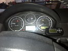
Thread upload130 viewsImage uploaded in thread 11806819 Nov 2014
|
|
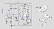
Thread upload413 viewsImage uploaded in thread 11359919 Jul 2014
|
|
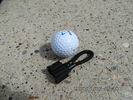
MOST fiber optic loop tool469 viewsThe looping tool in the jpg uses the Land Rover type plastic fiber optic cable with both ends feeding back into a female fiber optic connector that mates with the male fiber optic connectors on the Land Rover system.
The purpose of the loop is to allow one to disconnect MOST connected items such the BlueTooth module or the HK amplifier but allow the MOST system to still transmit signal from the head unit as the circuit would remain closed and hence complete. Of course with the Bluetooth module disconnected, there would be no Bluetooth available, however the radio and NAV would still function.
The looping tool allows one to troubleshoot the system by removing one component at at time from the MOST loop. In other words, what might appear to be a radio problem could be a Bluetooth problem - that sort of thing.16 Jul 2014
|
|

Electrical Connector Sleeve Replacement ZF 6HP26974 viewsThis 3 page pdf with pictures shows how to replace the sleeve that holds the multipin electrical connector that passes thru the transmission body to the Mechatronic unit.
The install of the sleeve is more difficult than the removal in that one must not rotate the sleeve as damage to the internal pins can result. The pan must be first removed to both remove and install the sleeve. 01 Jul 2014
|
|
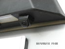
Tailgate Camera located above license plate.598 viewsThis aftermarket camera is mounted on my 2005 LR3 in almost the same location as the factory cameras. The factory units are mounted somewhat more forward closer to the metal of the tail gate and I could have done the same as well.
Note that the camera above is aimed a bit towards the centreline of the vehicle per the factory install. 26 Jun 2014
|
|
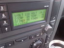
Voltage Display Page Radio Head Unit 118 14.2840 viewsThis shows the voltage/temperature/timer display page within the 6CD-465 radio head. There is a second file within this album, a doc file, that outlines the procedure to access the diagnostics.
The 14.1 volts number was the approximate vehicle system voltage with the engine running; the 118 number infers 11.8 volts which is the low power infotainment system shutdown cutoff voltage. The factory default setting is 135 or about 13.5 volts. By holding the keypad 1 button down, the 3 digit volts numbers will decrease 001 at a time until the keypad 1 button is released. Decreasing the number from 135 to some lower number should increase the time the system will remain on with the engine off.
The TEMP numbers refer to Fuel Burning Heater, (FBH), temperature values. 85 is apparently a high limit and 46 was the number when the jpg was taken. This number varies and given that there is no diesel fueled FBH in our NAS petrol engine vehicles, what the value refers to is unclear. The TIMER numbers also relate to the diesel fuel burning engine heater and perhaps make more sense being 00.21 Jun 2014
|
|

Mechatronic Sleeve Removal and Install Instructions1058 viewsThis 3 page pdf with pictures shows how to remove and install the Mechatronic sleeve that tends to leak tranny oil after about ten years. Even if not leaking, replacement when doing a pan/filter change at the ten year mark is suggested.
Note the 3mm or less requirement when sleeve installation is completed; also that rotation of the sleeve during the install procedure can do damage to some internal pins - hence do not rotate the sleeve when trying to insert it or in getting it to lock in place - not so easy it seems.26 May 2014
|
|

SDARS Satellite radio operating instructions 352 viewsThis is a 14 page pdf portion from the Owners Handbook with regard to operation of the satellite radio system operating on the Sirius channels.22 May 2014
|
|
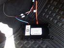
D4 Bluetooth AH42 10F845 AA module connected to 12VDC and MOST1210 viewsThis jpg shows the MOST bus connected to the AH42 10F845 AA module used in the D4 as well as +12VDC power from F58P connected. The power is split with a Y harness as the IHU (radio) for some reason required +12VDC power to the C2115-10 "mute" pin to keep the radio/CD audio from muting all the time.
With power on the pin, the radio audio does mute as it should when the cell phone rings and the hands free connects. The brown conductor feeds to C2115-10 and the blue to the module.
The module tucks up and hides behind the grey plastic section covering the forward portion of the passenger side tranny hump for left hand drive vehicles; for RHD, it would be located on the left side.
The pairing code is 2121 with this setup and not 1234 or 0000.14 May 2014
|
|

0000 LR Bluetooth dealer Kit install instructions1610 viewsThis 17 page pdf is mostly a series of pictures showing how to install the original Land Rover dealer installed Bluetooth kit for circa 2005 / 2006 three's. Also included are three wiring diagrams sheets related to the pairing code 0000 Bluetooth install.
This pdf is useful if you are now removing the 0000 kit to install the optical 2121 MOST D4 module, an easier install than the 0000 kit ever was. 26 Apr 2014
|
|

Anti Lock and Traction Control description and operation.1987 viewsNote on page 6 of this 17 page pdf the significance of the Steering Angle sensor mounted on the steering wheel shaft. The paragraph regarding the plausibility check as related to the brake pedal being not depressed is why the clean operation of the second set of contacts on the brake switch matters so much. 15 Mar 2014
|
|

Steering Column detailing Steering Angle Sensor1497 viewsItem 2 in the picture on page 1 of the 9 page pdf shows the location of the steering wheel sensor. Page 5 of the pdf has a paragraph describing the operation of the sensor. When the steering wheel does not point the same direction as the real wheels, then the computers can put the 3 into safe mode and down goes the suspension. See also the 17 page pdf on the Anti Lock and Traction Control pdf.15 Mar 2014
|
|
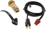
Block Heater and Cord for petrol V8 LR3 North America 120VAC529 viewsThe recommended 120VAC block heater cord is a Temro 3600003. This is a five foot long cord with what is called a Straight connector at the block heater end with holes for two pins; there is also a metal tab located between the two holes serving as the ground conductor. That cord, in addition to having the two pin holes plus ground tab end, is designed for both aluminum and brass heaters as that also matters.
The Land Rover part number for the Block Heater assembly is VUB504640 but is a Temro product not officially marketed by Temro as a Land Rover block heater. The Temro product number is 3100107 which shows as a brass body 30 mm threaded 700 watt 120VAC screw in block heater with a rectangular shaped depression and two pins suitable for the Temro 3600003 cord. Note the word BRASS as it mates with the aluminum OK.13 Mar 2014
|
|
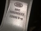
Part number moulded into spoke of 18" ten spoke. 322 viewsThis part number, RRC500250XXX is moulded into the backside of one of the spokes of the ten spoke 18" wheel. An alternate part number is ALY72190U or ALY72190U85 which relates to year and finish.
Another number is RRC500250MNH where MNH is also the finish, probably Sparkle Silver.02 Mar 2014
|
|
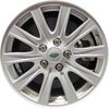
LR3 Silver 10 spoke grooved wheel Cromodora of Italy 18 inch x 8 ALY72201U85385 viewsThis is Land Rover part number RRC505360MNH or RRC505360XXX, a grooved ten spoke 18" wheel rated at 940 kg and found on circa 2006 RR Sports and some 2007 LR3's. An alternative part number is ALY72201U85.
This is an example of a wheel factory spec on the full frame older RRS that is also factory spec on the 3 or 4 and hence can be moved from the RRS to the 3 or 4. This is rare however. A factory spec wheel for a 3/4 can always go onto an older full frame RRS but not necessarily vice versa.
Just because a wheel is a 5 lug, 120mm bolt circle, +53 mm offset and made by Cromodora does not mean it has the required 940 km load rating. That also has to be confirmed by looking on the backside of one of the spokes for the moulded in load number in kg.02 Mar 2014
|
|
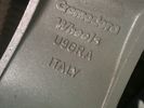
Cromodora brand marking on inside of spoke.326 viewsThis is the Cromodora brand marking on the inside of the 6 spoke 19" wheels, Land Rover part number ALY72191U. Similar brand markings are cast onto the inside surface of the spokes on all Land Rover Cromodora wheels.01 Mar 2014
|
|
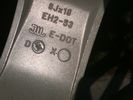
E-DOT and Japan wheel acceptance marking on ten spoke wheels.335 viewsThese are the E-DOT and Japanese wheel acceptance markings on the inside of one of the ten spokes of the 8J x 18" wheel, Land Rover part number ALY72190U or RRC500250xxx where xxx is the colour number, in this case, MNH for Sparkle Silver. There are similar markings on all Cromodora wheels for the 3.01 Mar 2014
|
|
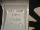
940 kg load marking on inside of spoke419 viewsThis is a typical 940 kg load marking on a Cromodora wheel rated for the 3. In this case, the wheel is the 6 spoke 19" wheel common to the HSE, LR Part # ALY72191U.01 Mar 2014
|
|

Transpo pdf explaining the operation of Ford PWM regulators625 viewsThe 4 page pdf produced by WAI-Transpo explains the operation of the Pulse Width Modulated regulators located within the alternators on our 3's. Of note, the pdf states that certain of the Ford PWM regulators do not meet Ford spec.
The pdf explains the function of all the terminals and the apparent advantages of the PWM style over previous designs. Note that Ford calls their "engine computer" a PCM, (Power Control Module), whereas Land Rover, an ECM, (Engine Control Module). 28 Feb 2014
|
|

Heated Windscreen Wiring Diagram408 viewsThis single page pdf is the heated windscreen wiring diagram. You can rotate the view by right clicking on the pdf and of course it can be printed out as well.
Relay R208 in the pdf is relay R9 in the Engine Compartment fuse box. Note both 30 amps fuses, F15E and F18E, also located in the Engine Compartment fuse box. If one side of your windscreen does not heat, the problem may be one of the two fuses.21 Feb 2014
|
|

Engine and Transmission Electronic Controls Wiring Diagram996 viewsThis 20 page pdf shows the wiring for the electronic controls for the engine, transmission and transfer case. 20 Feb 2014
|
|

Mechatronic Replacement Hints plus drains for steel and plastic pans1111 viewsThis 22 page pdf shows colour views of the Mechatronic unit as well as good illustrations of the drain and fill ports in both the plastic, page 17, and steel pans, page 18.
Page 8 details the replacement of the sealing sleeve where the electric wire feed thru the case into the Mechatronic unit. The seal is normally replaced when a new pan is installed as the seal is a known leakage point.17 Feb 2014
|
|

ZF 6HP26 and 6HP28 Comparison plus oil pan and filter replacement options963 viewsThis is a 66 page ZF produced pdf that provides comparisons between the various ZF transmissions; also instructions regarding maintenance of the Mechatronic unit, the round seal; the various metal and plastic pans available as well as tips regarding changing the oil.
This ZF pdf has a number of colour pictures and part numbers within as well.13 Feb 2014
|
|

Engine Accessory Drive Description and Operation884 viewsThis 2 page pdf shows both belts for the 4.4L petrol V8; the primary serpentine belt, (the long one), and the shorter secondary that drives only the radiator cooling fan.
The various accessory pulleys the two belts are each associated with are numbered and an included table describes each.
When replacing belts and pulleys, count the number of grooves on both your old items and your new replacement parts. It has been known for an pulley with the wrong number of grooves to come with a replacement part or the replacement belt has the incorrect number of grooves; hence make certain the groove count on the new parts are the same as the removed items.
09 Feb 2014
|
|

ZF 6HP26 Transmission Cooling System Description and Operation2938 viewsThe five page pdf details the operation of the cooling system as related to cooling engine oil, transmission oil and providing hot water to the cabin heating system.09 Feb 2014
|
|

Rosen A10 Land Rover Installation Manual841 viewsThis is a 11 page pdf which is the Land Rover version of the A10 installation manual for our 3. It consists of a hundred plus sketches showing how and where to connect various cables, conductors and plugs.08 Feb 2014
|
|

Rosen A10 Manufacturer Installation Manual763 viewsThis is a 30 page pdf from Rosen that explains how to install the A10 unit. It is Generic in nature and hence carries detail not found in the LR specific install instructions. It also uses words and pictures instead of just pictures, hence can be a bit easier to figure out, particularily if you wish to take advantages of some of the hidden features not described in the LR material.
One of these features is how to hook up to a headrest display or I suppose even to the NAV in front.
08 Feb 2014
|
|

Rosen Owners Manual894 viewsThis 28 page Owners Manual is the Rosen version written specifically for the A10 model DVD Video Game Entertainment System player that may in attached to the roof of your 3.
Discussed is how to use the remote control, the wireless headphones, the TV feature if installed, and how to change from 16:9 widescreen format back to the older 4:3 format.08 Feb 2014
|
|
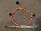
Fibre Optic MOST cable between components.560 viewsThis is a typical section of Plastic Optical Fiber (POF) optic cable with the orange coloured cladding covering the perimeter of the light transparent core. This is used as the MOST (Media Oriented Systems Transport) data transmission medium.
Note that each MOST 1355426 optical connector holds a pair of light conductor cables, one transmitting optical signal in, and the second, optical signal out. When connected to the other cables and devices, the cables form a continuous loop.
The light signal within the cable is red colour as one might expect. One break or disconnect anywhere along the loop shuts down signal transmission to all the connected components.05 Feb 2014
|
|

419-08 Low and High line radio systems components and operation838 viewsThis 15 page pdf displays the radio components including pinouts for both the low and high line head units and the two Harman Kardon amplifiers including the Logic 7 amp. The steering wheel controls for both the radio and phone system are also outlined along with mention of the Sirius satellite radio feature. 05 Feb 2014
|
|

415-02 Antenna systems for AM/FM, Satellite, GPS and TV systems542 viewsThis is a 5 page pdf related to the antenna systems for the AM/FM radio, Satellite radio, the GPS/NAV and the optional TV.05 Feb 2014
|
|

415-03 Audio System - Low and High Line Radios934 viewsThis 8 page pdf shows both the low and high line radios and their various components.05 Feb 2014
|
|

415-07 Video Information724 viewsThis is a 5 page pdf that explains the operation of the overhead DVD setup as well as the TV option.05 Feb 2014
|
|

Fibre Optic MOST bus plus CAN, LIN, GVIF and SLIN buses1539 viewsThis 7 page pdf introduces the fibre optic MOST bus, (the orange coloured cables), the two high and medium speed CAN buses, the Gigabyte Video InterFace, Local IntercoNnect, and Security Local IntercoNnect buses.04 Feb 2014
|
|

Entertainment System Wiring Diagrams2331 viewsThe 12 page pdf has the wiring diagrams for the low and high line "radio" and various components such as the amplifier, phone modules,NAV display, antennas and satellite radio and TV.04 Feb 2014
|
|

GPS NAV system components and operation999 viewsThis 16 page pdf describes the operation of the GPS navigation system and provides pin outs and equipment layouts. The GPS antenna amp and location is also shown. 04 Feb 2014
|
|

Older Cell Phone handset holder operation and components849 viewsThis 8 page pdf explains the operation of the older Cell phone handset holder and shows the various components as related to the radio and phone buttons etc. 04 Feb 2014
|
|
![Filename=LR3_Radio_Removal[1].pdf
Filesize=190KB
Dimensions=320x240
Date added=04.Feb 2014 LR3_Radio_Removal[1].pdf](images/thumb_pdf.jpg)
Radio Removal from Radio Stack572 viewsThis shows how to remove the radio from the stack. Basically you remove the H surround first and then at least loosen all the Torx 20 screws left and right sides from the top down starting at the narrow unit that the four way flasher/locking buttons are mounted on.
The units kind of interlock, hence some movement of each is required to remove the radio by itself. I find it best to take out the four way flasher/locking buttons assembly first as that allows access to the fibre optic cable connector into the back of the radio head without too much tugging.04 Feb 2014
|
|
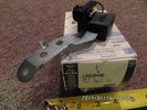
Radio Noise Filter Transmission Electronic Control Unit915 viewsThe jpg shows part number LR020488, a noise suppression capacitor located underneath on a bracket on the right side of the transmission forward of the selector shaft lever. The suppressor is connected to the transmission wiring harness and prevents solenoid operating noise affecting the audio system.
Failure of the capacitor is most often discovered as a result of either black smoke from below and or the blowing of 10 amp fuse F30E located in the engine compartment fuse box. This fuse protects the power circuit to the Transmission Engine Control Unit. When the fuse blows, the engine will still run however you have no gears, hence movement of the 3 is inhibited.
Anything over eight years in service is considered good capacitor life. If the capacitor does fail and fuse 30 blows, a quick fix is just to disconnect the capacitor and replace the fuse.
The capacitor might be missed by the DOT/FCC but the 3 does not seem to mind. With the filter disconnected, solenoid noise might be heard on some radio stations but at least the 3 would be in motion.17 Jan 2014
|
|

Console Gear Selector Wiring Diagram960 viewsThis is a 3 page wiring diagram centered around the console located gear selector.09 Jan 2014
|
|

A Pillar Black Plastic cover install pdf - new type.1039 viewsThis 3 page LR pdf explains how to install the newer A pillar plastic covers and avoid instant water leakage as a result of the new design.13 Jul 2013
|
|

Rear Area Climate Control System1161 viewsThis 14 page pdf describes how the rear heating AC system is supposed to operate in conjunction with the front system.
The air transfer ducts are shown as coloured sketches as is the air flow within the rear blower setup. 06 Jun 2013
|
|

Air Conditioning and Heater Control Components2425 viewsThis is a 21 page pdf that really explains how the air system is supposed to work. Discussed are the exterior ambient air sensor, where and how it operates; the interior temperature sensor as well as humidity sensor.06 Jun 2013
|
|

Air Distribution and Filtering Systems2084 viewsThis is 3 page pdf with coloured drawings of the air distribution ducting for the front air system.
Also included is a sketch of the pollen filter location within the front heater ducting. Note that two types of filters are available: a) the cheaper dust/pollen filter and b), the activated carbon filter that removes smells from the air. Installing the more expensive activated carbon filter means you never smell a cattle truck or chicken farm again. It really works.06 Jun 2013
|
|

Air Conditioner Specifications 4.4L V81570 viewsThis 2 page pdf is just the specifications for the AC system. The refrigerant type is R134A.
Note that when topping the system up, it can be a good idea to include some of that ultra violet light dye that will glow to show leaks and loose fitting. 06 Jun 2013
|
|

Front Differential Description and Operation1543 viewsThe 4 page pdf describes of the operation of the front differential plus displays an exploded view of the front differential.
The fill plug is item 36 and the drain plug, item 8.
It is suggested one first unscrew the fill plug before unscrewing the drain plug - and it might take two different wrench sizes, hence get this detail sorted out before any oil drains out.12 May 2013
|
|
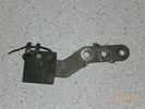
Radio Noise Suppression Capacitor NNW502820699 viewsThis is the radio noise suppression capacitor, part number LR020488 (previous NNW502820), that is mounted underneath and near the transmission. It is powered by fuse 10 amp F30E in the engine compartment. If F30E blows, (the fuse that also powers the transmission ECU), the problem is probably caused by the failed capacitor, not the ECU. A quick fix is just to disconnect the capacitor and replace the fuse as nothing bad seems to immediately result.
The above radio noise capacitor is not to be confused with LR004160, the ignition noise capacitor which is located under the black plastic engine cover on the right hand side above the air intake towards the rear of the engine.
The ignition capacitor is held on with a single 8mm bolt and a three wire electrical connector. Replacing the ignition capacitor as a routine maintenance prevention action at 100,000 miles, 160,000 km), has merit. It is a do it yourself kind of thing and easier to get at than the radio capacitor underneath.
02 Apr 2013
|
|

ZF 6HP 26X Description and Operation1573 viewsThis is a Land Rover produced 47 page pdf describing the operation of the ZF 6HP26X six speed tranny that is in our 3's. There are colour cut thrus of the various tranny assemblies, both electrical and mechanical, along with an explanation of their intended operation.28 Dec 2012
|
|

Fuel Tank Internals, Description and Operation 809 viewsThis 10 page pdf shows views of the fuel tank internals, what the various pieces do and describes how the fuel storage system is supposed to operate.
As usual, you can download it, save, and print as required.06 Oct 2012
|
|
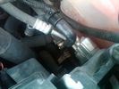
Breather Cap Installed2008 viewsThe black L shaped tube is is the Gore manufactured, (the Gore-Tex people), LR4 Breather Valve installed in an LR3. Naturally the installation looks similar to what one sees on an LR4 or RRS as the Gore breather valve is now OEM for new production.
The part number of this upgraded front differential breather valve is LR019450 and costs about thirty dollars.08 May 2012
|
|
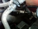
New Breather Cap installed.1712 viewsThis shows the new Gore brand angled breather cap installed. The cap points rearward to the firewall. Also shown is the cut off piece.
The new Gore breather cap is what one now sees on the LR4 and RR Sport.07 May 2012
|
|

Breather Hose exploded view.1232 viewsThis pdf shows the exploded view of the breather hose from the front differential to the engine compartment. The breather hose part number is TAP500081 and is identified as 4A058 in the drawing.07 May 2012
|
|

Gore Tex data sheet on Breather Cap.784 viewsThis is a Gore data sheet on the air vent material that is within the breather cap. The filter material has both hydrophobic and oleophobic properties. That means it keeps water out and the differential oil in.
Also the membrane material is air permeable; that means air pressure is equalized between the interior of the differential and outside air. This is important when the 3 is flying at altitude in the back of a Hercules with the rear door open - that is the rear hatch of the Herc.07 May 2012
|
|
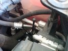
Vertical Breather Hose before cutting off OEM cap.1779 viewsThis shows the plastic vertical breather tubing and OEM cap prior to being cut off. The tubing is located on the driver side at the front near the radiator. One cuts about 3/4" to 1" off from the top. The TSB says 20mm.
I tried blowing thru the cut off piece and was not very successful. The cap seemed plugged. I am beginning to think that there was a very good reason for Land Rovers's Technical Service Bulletin, (TSB).07 May 2012
|
|

Land Rover TSB LTB00245 install instructions1940 viewsThis is the Land Rover Technical Service Bulletin showing how to install the new breather cap. The instructions are a bit vague re cutting the existing air vent tubing on a 45 degree angle with the cut facing to the rear.07 May 2012
|
|
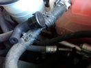
Breather line with factory cap cut off.2320 viewsIf you expand the jpg by clicking on it, in the bottom right corner if you look closely, one can see the black plastic factory vent tubing with the OEM cap cut off.
Note the tubing is cut at a 45 degree angle facing to the rear. Also shown in the top right is the cut off portion sitting on the coolant water hose and on the top left also sitting on the coolant hose, the new to be installed Gore manufactured replacement breather cap.07 May 2012
|
|
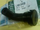
Breather Cap part # LR0194501541 viewsThis is the replacement breather cap as manufactured by the Gore Tex people, (Gore), for the engine compartment end of the front differential breather line.
You can with some difficulty, both blow and suck thru the breather filter material. The Gore Tex filter material has what are called hydrophobic and oleophobic properties. This means the filter material keeps oil in and water out, while at the same time, allowing air pressure to slowly equalize, (air permeable). Additionally, the transfer of dust, salt, and road debris is inhibited.07 May 2012
|
|

Wipers, Front and Rear, plus Washers description and operation.818 viewsThis 17 page pdf describes how the wipers, front and rear, plus the washers are intended to operate. Also described is how the rain sensor is designed to function along with a table of the wiper delay timing parameters.09 Mar 2012
|
|

Excel file for Rotors and Brake Pads part numbers for 4.4L V8 petrol LR3769 viewsComparing the cost of the various brands of brake parts is time consuming. Once you have your parts costs, this little spreadsheet will make collating the info easier.
I did not make any provision for labour costs, but the file can be downloaded and then modified. You can change Dollars to Euros or Pounds or whatever and insert lines for labour costs as desired.
Do not pay too much attention to the $ numbers as they are a mix of US and CDN, and from differing time frames, (prior to Spring 2011) . Also the brake part numbers are for my 2005 North America spec LR3 with the petrol 4.4L V8; diesel powered and supercharged 3's may have different part numbers
09 Feb 2012
|
|

Alternator and Regulator Wiring Diagrams, TDV6 and petrol V8 and V61989 viewsThis is a three page pdf that shows the alternator and regulator wiring for the petrol V6, petrol V8 and TDV6. The pdf can be either printed or by right clicking on the displayed pdf, rotated as required for viewing.
Of interest is that the regulator gets its instructions primarily from the Engine Control Module (ECM) and only secondarily from the vehicles electrical buss. The conductor from the battery thru the 5 amp fuse F20E is to provide initial power to excite the alternator at startup and then secondarily, to instruct it if the PWM signals were not available. Primary instructions to and from the ECM are thru the two other conductors via a digital like Pulse Width Modulated (PWM) signal.
If F20E, the 5 amp engine compartment fuse box fuse is blown, the red alternator light on the dash will be illuminated. This means that the alternator could be OK, but if the F20E fuse is blown, no electricity will be generated. Hence check the F20E fuse if you get a red ALT light or some indication of the alternator not working.
Regarding operation of the red ALT light on the dash, it is not the regulator within the alternator that tells the red light to illuminate, or not, but instead the ECM. This is the reason the red light does not function in the same manner as with older vehicles. With the 3, sometimes you have illumination and sometimes not depending upon what the ECM is thinking. What this means is that you can have an alternator that is failing but the red light does not illuminate as the ECM is compensating for reduced alternator output - maybe by draining the battery and or cutting back on vehicle electrical loads such as shutting off or cycling the radio amplifier or heated seats.07 Feb 2012
|
|

Transpo Regulator IN6349 Pin Assignment716 viewsThis pdf shows the Land Rover and Ford pin naming for the 3 pins in the receptacle of the Transpo IN6349 regulator that accepts PWM signals. This jpg is as if you are looking into the receptacle located on the alternator.
Also provided are the Transpo pin names that are in common use and that some may be more familiar with plus some comments re testing.
The IN6349 regulator is used in the newer LR part # YLE500390 alternator. For the older YLE500190 alternator, the regulator is a Regitar VRH2005-142 unit that is shaped a bit different than the newer IN6349 regulator. Externally, the main difference is that no shiny fins are visible on the rear of the newer YLE500390 alternator. The pin naming and numbering is the same for both and both alternators are interchangeable. 06 Feb 2012
|
|
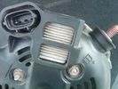
Alternator Plug and B+ terminal919 viewsPictured is the rear of the older Land Rover part # YLE500190 alternator showing the shiny cooling fin of the Regitar VRH2005-142 regulator under.
The first pin in the far left side of the connector is numbered #1 in the LR electrical wiring diagrams and is Battery Voltage Sensing (BVS); the middle pin, #2 receives a Pulse Width Modulated (PWM) signal from the Engine Control Module (ECM), and the right pin, #3 carries a PWM signal back to the ECM. Terminal Pin #2 on the LR wiring diagrams is called Alternator Control or ALT CON; Pin #3 per LR is called Alternator Monitoring or ALT MON.
Pin #1 is similar to what in older designs used to be called A or Batt, but is now called by Denso, S, AS, or Alternator Sensing for this design. Pin #1 also provides power to excite the alternator at startup until the PWM instructions over ride the battery voltage info. Land Rover calls the electronics under the pins a Smart Regulator, ironic, as it has to follow orders from the ECM rather than give the orders - new age thinking I guess. This is different from older design internal regulators that look at just the battery or the electrical buss voltage and then decides itself what to do.
It is almost like we are back to the external regulator designs of old, except that the ECM may decide that instead of telling the alternator to make more power, to load shed, and hence shut down the heated windscreen, seats, or whatever other electrical loads it decides are appropriate. My view is that the "smarts" are in the ECM and that the "regulator" should be regarded if not dumb, then as being a slave to the ECM.31 Jan 2012
|
|

Seats and Memory Description and Operation226 viewsThis 14 page pdf details the operation of the key fob memory functions related to the seats, and on page 7/14, the dip function re the exterior mirrors. 25 Jan 2012
|
|
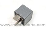
Air Compressor 70 amp replacement relay1393 viewsThere is a software update, 09 April 2010, LTB00270, for the compressor which reduces the shut down pressure to about 205 psig (14 bar). The update is usually done when changing to a new compressor and also includes replacing the R7 relay in the engine compartment fuse box, 07 DEC 2010 LTB00331.
The newer grey case coloured relay, part # YWB500220, shows to be rated at 70 amps, (the relay, not the compressor), however the previous black case coloured relay also indicates 70 amps.
Both the new and replaced relay show on their wiring diagrams to have a parallel voltage spike resistor, (probably 560 ohms), across the coil terminals, #1 and #2. This means one does not just replace the relay with any four prong 70 amp ISO sized relay that one happens upon.
One presumes the grey relay is either upgraded or just being installed for good measure. The relay is common on Ford Fiesta for the seat heater relay, Ford part number 5M5T 14B 192 EA; also Volvo, part number 30765034. The Tyco part number moulded on the grey body is V23136-J4-X62.
14 Jan 2012
|
|
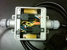
Box open showing Hella Relays and Putco Load Resistors749 viewsInterior of the box - note the two gold coloured 6 ohm 50 watt load resistors are a bit distant from the other items so as to provide some separation for dissipation of the heat generated.
Rather than a moulded plastic weather resistant box which I would have preferred, I used a bulky and much heavier metal weather tight style electrical box so the metal can act as a heat sink.07 Jan 2012
|
|
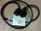
Box Closed with 7 Blade NAS connectors586 viewsBox closed up and ready for use. The box and cable connectors are reasonably weather tight and hence can be submerged for a bit while doing a creek crossing but as with the 3, do not use the creek bed as a parking stall. Similarly, the connector recessed into the bumper will probably remain somewhat dry as long as you keep moving but if you get stopped, well that is another story.
As such, I put a vial of desiccant in the metal box prior to closing it up to reduce corrosion due to moisture build up.07 Jan 2012
|
|

LED trailer lights adapter for LR3844 viewsThis doc includes a partial list of materials and the instructions/links required to construct an adapter to prevent LED trailer lights from pulsing due to the 3's diagnostic circuits interrogating the signal light circuit.
Using the adapter also facilitates the green flashing of the dash located trailer indicator when the signal lights operate plus inhibits operation of various systems such as the backup sensors, etc.07 Jan 2012
|
|

JAE connectors for the upper hatch switch and FAKRA connectors for the Sat NAV.539 viewsThis jpg shows some catalog pages listing the MX19 connectors used on the upper hatch switch.
Also shown are the FAKRA connectors that are used on the rear of the Sat NAV.04 Jan 2012
|
|

Part numbers for JAE connectors for the upper hatch switch. 382 viewsThis lists the JAE and Digi-Key part numbers for the electrical connectors for the hatch switch.
I contacted Japan Aviation Electronics and they directed me to Digi-Key in the USA who sell odd lots of the JAE product, odd lots meaning two pins and one connector if that is all you wish.04 Jan 2012
|
|
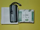
Upper Hatch Release Switch LR Part Number YUZ500020676 viewsThis is the Range Rover Sport switch, Land Rover part number YUZ500020, as it comes out of the box. Note the JAE, (Japanese Aviation Electronics), male wiring connector installed on the end of the power lead.
The rubber cover of the switch is sealed to the plastic body of the switch whereas in the previous switch design, there was no sealing. Also the replaced switch was hard wired into the same harness as the license plate lights - no JAE connector in other words.04 Jan 2012
|
|

Replacement switch from RRS installed on LR3864 viewsThe switch shown is LR part number YUZ500020, the upper rear hatch release switch that is found on the Range Rover Sport.
The switch body is the same switch as on the LR3 except that there is no wiring disconnect on the LR3. Hence when the switch corrodes and requires replacement, the LR solution is to purchase a new handle and license plate light assembly. I instead cut off the old switch and installed a JAE mating connector to the existing wiring and hence just plugged the RRS switch in.
The replacement RRS switch snaps into the same rectangular space in the same manner as the removed LR3 switch, the difference is the JAE male wiring connector.04 Jan 2012
|
|

Door Lock Wiring Diagrams1730 viewsNear the bottom of this 5 page pdf on page 224 are shown the pushbuttons and locking mechanisms for the rear hatch and tail gate.
The pdf will open vertically but you can download and print it out or just rotate the image clockwise by right clicking on your screen and selecting the "Rotate Clockwise" button.03 Jan 2012
|
|

Power and Heated Seats Electrical Schematic979 viewsThis 6 page pdf shows the wiring for the power adjustment of the front seats and seat heating for all the seats.
Re seat movement or the lack of, not only are there four related fuses, two 30 amp and two 5 amp, (one of each per seat), there are are two separate ground wires, perhaps of more significance than the power, if all movement on either side quits. 14 Dec 2011
|
|

Lug Nut part number RRD500290 outline sketch541 viewsThis single sheet pdf provides dimensions of the LR part number RRD500290 lug nut on vehicles from MY 2005 to 2008, (up to VIN 8A450459). From VIN 8A450460, the part number is RRD500590.
Visually, there is no apparent difference between the two part numbers. The dimensions appear identical as well. The shape, size, and profile of the Stainless Steel "hat" appears identical.
There are I presume differences in metallurgy to reduce corrosion and swelling of the hat or perhaps better sealing between the inside surface of the hat and the steel of the lug nut body. The reality is the differences are not immediately obvious however.
A 22 mm six point half inch or larger socket drive fits over the lug nuts. I use a nominal 36" long breaker bar with the 22mm socket - any shorter bar, best you be in shape. Depending upon your source, for both alloy and steel wheels, the lug nut torque value appears to be 103 lbf ft, (140 Nm); others suggest first tighten to 96 and then finish at 110 lbf ft, (130 and 150 Nm).
10 Dec 2011
|
|

Vehicle Maintenance Log for LR3/4 D3/4 or other1135 viewsThis is a Excel file that you can download and then modify to suit. It is very simple, but allows me to keep track of most maintenance and fixes etc on my LR3. All columns and rows and boxes can be edited.
I did not erase any data in the various boxes so you could see how I am using it - again not very fancy but it works for me. Under the brakes column, one will see f6 r5 which is how I keep track of the condition of the brake pads. The dealer records the pad thickness at each oil change so that is where the numbers come from.
f is for Front Pads, 6 is for 6mm; r is for Rear pads, 5 is for 5 mm. New pads are about 10 mm; replacement is at 3 mm or less. The amber coloured brake wear dash warning light should come on at about 2 mm.15 Nov 2011
|
|

Fuel Purge Valve and other hoses.846 viewsThis 6 page pdf shows the Fuel Purge Valve and associated hoses and describes how it is supposed to work. There are lots of good drawings of the fuel system. It is more complicated than one might think.14 Nov 2011
|
|

ZF LifeguardFluid6 transmission oil.1397 viewsThis is an interesting pdf in that under the ZF 6HP26 six speed section, it provides the various automobile manufacturer part numbers for their version of the appropriate tranny oil, all of which seems to be the LifeguardFluid6 oil, ZF part number S671 090 255. Note the fine print and do not confuse it with the LifeguardFluid6 Plus oil for vehicles with the Torsen AWD setup such as the Audi Quattro, VW 4Motion vehicles and I think the BMW FF Range Rovers of an earlier time.
Also of interest at the bottom of the pdf is the recommendation for replacing the transmission oil "between 80,000 km and 120,000 km or 8 years, depending on the load." I also do not see any reference to "sealed for life" but almost as optimistic, "maintenance free" but with the proviso "intended for normal operating conditions". This would most typically be the Sandringham Castle Grounds in the UK rather than Cape York, QLD.09 Nov 2011
|
|

Torque Converter cut away ZF 6HP26X tranny1550 viewsThis is a cut away of the model year 2005 ZF 6HP26X six speed automatic transmission. This is about as good a section of a torque converter, (the shudder maker), that I have yet seen.09 Nov 2011
|
|

Troubleshooting pdf re Mechatronic unit on 6HP26 ZF Automatic 2145 viewsThis 21 page pdf shows possible problems within the Mechatronic unit of the ZF 6HP26 six speed automatic. On page 19/21 is a drawing showing how all the various control circuits interface with the vehicle.
Of particular interest were comments with regards to fine metal contamination of various electrical contacts. This is probably why a mere oil change can improve the operation of the transmission - reduced conductivity of the oil.10 Oct 2011
|
|

Power Window Wiring Diagrams417 viewsThis pdf shows the power window wiring diagrams which are also shown as jpgs 1,2 and 3 below.31 Aug 2011
|
|

Central Door Locking Operation Description1458 viewsThis 17 page pdf explains how the door locks are supposed to operate. Note that on page 9/17, the explanation of the operation of the hood ajar switch is wrong. It operates similar to the door and tailgate ajar switches; that is when a "door" is closed, the switch is closed to maintain a ground back to the CJB. Opening the hood, door, or tailgate removes the ground breaking the circuit and hence allows for an alarm condition.30 Aug 2011
|
|

Cooling system hoses - 4.4L petrol V81109 viewsThese are the cooling system hoses on the 4.4L petrol V8. The little odd shaped bleeder hose, (LR006158), shown in the top right hand corner can give problems. There is a plastic tee with a threaded air bleeder outlet located in the middle of the hose. The plastic tee can or will fail due to I guess heat distress.
A BIC pen can serve as a field fix, however for your parts kit, a nominal 3/8" ID hose size brass hose barb inline connector plus a couple of hose clamps is suggested. Better yet is a threaded hose barb brass coupling or a tee and bleeder valve to allow bleeding of the line. Land Rover now makes the plastic bleeder valve that breaks available as a separate part, # LR027661, where 0 is a zero. As such, one can now purchase that part only for addition to your field fix parts kit.10 Aug 2011
|
|

Horn Wiring Circuit LR3578 viewsThe is the wiring diagram for the dual horn circuit.
The Horn Relay, (R133), is not a big black thing hidden somewhere but instead what is called a FET, (and it is hidden)!
This is a Field Effect Transistor that is built into the circuit board that is mounted to the back of the fuse box that is located behind the lower glove box door on the passenger side of the 3. The related 15 amp fuse, 12P, is mounted in this fuse box and is often called F12P, where F is for fuse, and P is for Passenger compartment.
This is to help differentiate from another fuse and relay box, (the usual kind), that is located beside the starting battery in the Engine compartment. FxxE is often used in the naming of those fuses.06 Aug 2011
|
|

Fluid, Filter/Pan Combo removal and install5980 viewsThese are the LR instructions re removal and install of the plastic pan/filter combo for the ZF 6HP26X transmission on the 4.4L petrol V8 LR3.
The instructions tend to ignore the reason you have to lift the right hand side of the engine about 40 mm. This is because of a frame cross member that interferes with dropping down of the plastic pan. The real problem is a vertical "oil filter spout" that rises out of the filter/pan combo up into the transmission. The spout is the suction pipe for filtered transmission oil back up into the tranny.
On the metal pan versions, the filter is separate from the pan, hence the filter remains with the tranny when the metal pan is dropped. The filter is then removed or installed independent of the metal pan, hence with the metal pan, there is no need to lift the engine.
If one is removing the plastic pan so as to install the metal pan, then some do not lift the engine but just drop the plastic pan enough to gain access to saw off the vertical plastic spout - it is a one time procedure.
Be aware however that the metal pan uses a flat gasket and the plastic pan uses a O ring like perimeter gasket that sits in a half round groove in the tranny casing. Also the metal pan uses 21 shorter torx M6x22.5 metric cap screws for the perimeter bolts. The plastic pan uses longer M6x28.5 torx metric cap screws.
29 Jul 2011
|
|
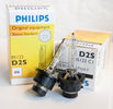
Philips D2S 85122 C1 Xenon 4300K projector HID bulb962 viewsThis is the 4300K OEM bulb in our HID Xenon projector headlights. People who design illumination systems regard the 4300K colour as a good compromise to provide what is called definition. This is effectively the ability to actually determine what an object being illuminated probably is. The more blue colour bulbs, say 5000K and greater, result in a reduction in the ability to distinguish detail, (regardless of brightness), of the object being illuminated. Effectively, you can see the object but you cannot quite figure out what it is. This is because the more blue frequencies means there are fewer other frequencies of light that allow our eyes to actually discern what an object really is.
The 4300K colour temperature applies to clear air conditions; for rain, dust, snow, fog, etc, then a yellow 2500K colour temperature is preferable. 2500K provides more contrast and there is less back splash of light off the air particles. In blowing snow, this means less sparkle back. Flat top cut off of the light beam, (which is the pattern our projector lights have), is important to reducing back splash - hence you do do not want roof mounted lighting for adverse conditions - as low down as possible is preferable, (which is why fog lights generally sit low.)26 Jul 2011
|
|

Power Door Lock Wiring694 viewsAbove is a 5 page, (pages 222 to 226), pdf wiring diagram for the power door locks for the LR3.
You can download and print as required. For on screen reading, use the right click rotate feature.
Additional pdf's regarding Locks can be found within the Gallery under the Power Windows and Door Lock Circuits heading.23 Jul 2011
|
|

LR3 Air Conditioning High Line electrical wiring diagrams1466 viewsThis 7 page pdf shows the wiring for the Heater/AC both front and rear.15 Jun 2011
|
|
![Filename=LR3_BMW_Ford_ZF_6HP26X-28X_Catalog_with_metal_pans_[1].pdf
Filesize=1194KB
Dimensions=320x240
Date added=26.May 2011 LR3_BMW_Ford_ZF_6HP26X-28X_Catalog_with_metal_pans_[1].pdf](images/thumb_pdf.jpg)
ZF 6HP26X and 6HP28X transmission parts showing various pans2814 viewsThis 42 page pdf is probably the most informative of all the material in this album. It is called a spare parts catalog but is much more than that. The material is specifically for the X variety of ZF six speed transmissions that are in the Land Rover 4WD / AWD models as well as BMW and Ford AWD vehicles.26 May 2011
|
|

ScanGauge II Manual 341 viewsThese are the setup instructions etc for the ScanGauge II version 5.1 There are newer versions that can be downloaded from the website www.scangauge.com as the software is subject to update; also the ScanGauge unit you purchase can later be sent in for updates as you might wish.20 May 2011
|
|

Air Suspension Wiring Sheets3037 viewsThese two sheets show the wiring and fuses related to the operation of the air suspension system. Fuses F3E, F26E, and F35P are shown as well as the interior up down switch and the wheel height sensors.
As with all pdf's, you can rotate them to view plus download and or print out as you wish.17 May 2011
|
|

ZF 6HP26 Metal Pans, (top and bottom views), and separate Filter top and bottom views.1765 viewsThis single sheet pdf two views of the ZF metal pan for the 6HP26 transmission. The inside view shows the two magnets; the other is the bottom view. Also visible are the transmission bottom oil fill and oil drain holes that are sometimes utilized where access to the side fill is not possible. The ZF part number for the metal pan kit for our 6HP26X six speed is 1068_103_820_01 This includes the 21 shorter Torx screws, the metal pan gasket, and the separate oil filter as well as round filter seal. The ZF six speed LifeGuard6 transmission oil is extra. 16 May 2011
|
|

Frame Jacking Points showing where holes are located.1088 viewsThe four points marked with the arrows show where the holes in the underside of the frame are located such than one could insert a trolley jack pin type lifting adapter, (or as designed), the official LR scissors jack.14 May 2011
|
|
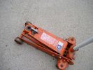
Trolley Jack Adapter824 viewsThis shows my 2.5 long ton, (2,540 kg, 5,600 pounds), trolley jack with the pin adapter that slots up into the round holes on the underside of the frame.
Use of the adapter when lifting by the left rear wheel ensures that I will not be jacking on the air compressor support; on the other three corners, it is much safer than merely jacking directly on the nearly flat narrow underside of the frame rail.14 May 2011
|
|

ZF6HP26X fluid fill checking procedure2257 viewsThis are the single page ZF instructions for checking the fluid level in the 6HP26X six speed automatic that is in the LR3.
Included sketches show where the fill and drain plugs are located and that it requires a 8mm hex wrench for the filler plug and a 10mm for the drain for the plastic pan.14 May 2011
|
|

Defender in the Fog, another day on the job.459 viewsThis is another normal work day for a Defender - actually the jpg is from a Land Rover advertising shot, but it may just not be a set up one. I think it is an actual working Defender. Note the visible front tow hook and how the hi lift is just rope tied on; also the normal stock headlights and I guess dual spare tyres - just another day on the job.13 May 2011
|
|

Power Door Lock wiring diagrams530 viewsI thought I would include this 5 page power door lock wiring diagram pdf here as well.
When the pdf loads, if the views are vertical, it may be that you can right click on your mouse and a box will come up that will allow you to rotate the views clockwise so that the sheets are horizontal. Alternatively you can download the file and print each sheet yourself.12 May 2011
|
|

Key in Ignition Electrical Wiring Diagram1051 viewsThis shows the key in ignition wiring, (LGW, 1.5D), running from the key lock cylinder to the Central Junction Box, (CJB), thru 5 amp fuse F40P, located in the fuse box behind the lower glove box door.
You can remove the 5 amp fuse and the good news is that the ignition chime will not sound any longer; the bad news is that a bunch of other circuits that rely on knowing if the key is in or out no longer work.
Also note the Transponder Coil D219 reference.12 May 2011
|
|

Add A Circuit Littelfuse Data sheet2278 viewsThe switch connects to what Littelfuse brand calls an Add-A-Circuit model FMH200BP which is an adapter that plugs in place of a Mini fuse and then has space for two Mini fuses, (original and a second one). In this install, only the original 5 amp fuse was used - adapter was so as to route power from fuse box thru fuse, then rocker switch, and then back to fuse box.
Before you install the Add A Circuit for this application, take an ohm meter and trace out the circuit path of the four slots that fuses could insert into. The path is more complicated than one might first think. As such, the orientation of the fuse holder in the socket matters for this application - that is for a circuit diverter, rather than accessory adder.
11 May 2011
|
|

Exploded Parts view calling up 6R60/80 and 6HP26/28 variations3113 viewsThis single page jpg exploded parts view indicates some commonality between the Ford and ZF versions of the early and later six speed units. Technically this sheet is for the RWD units as there are variations between plain RWD units, 4WD, and AWD. The transmission in the LR3 is called by ZF to be a 6HP26X and by LR in some publications, the 6HP2610 May 2011
|
|
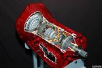
Ford 6R60 six speed cutaway showing torque converter.2198 viewsThis is a cutaway of the Ford 6R60 six speed which is a Ford license built version similar to our ZF 6HP26 six speed speced on early 3's.
The newer 3's and 4's have the ZF 6HP28. The Ford version is called the 6R80 and variations of it are used on the Raptor. As such, the Raptor metal pan can be installed on the 3's tranny but the deeper Ford Raptor pan does not have a drain plug. 10 May 2011
|
|
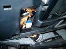
Smooth Talker Amplifier Box mounted below near steering column.179 viewsThe gold look box due to the lighting, (actually black), is the antenna amplifier located near the steering column. It can be put anyway but this seemed an OK location as I ran the antenna connector cable rearward from here to the back corner of the 3 and then up to the underside of the roof glass at the rear. The blue/white thing is the brake light switch that often must be replaced. See the Brake Light Switch file within this Gallery regarding the switch replacement.09 May 2011
|
|
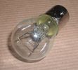
Land Rover Stop Tail Light dual filament bulb nominal 12 volt 21 / 5 watt filaments1427 viewsThis is the Land Rover part number 264590 dual filament bulb, (P21/5), that inserts into the upper two tail lamp receptacles. In the upper one, both filaments function, in the lower one, only the 5 watt tail light filament functions.
I regard it as not a good practice to routinely switch bulbs when the tail light filament, (5 watt), burns out on the lower bulb. The broken filament can jiggle over onto the brake light filament, (21 watt), and short the circuit to ground or something else not predicable.
There are also arguments to say that quality control is better on the Land Rover marketed bulbs than say far east sourced bulbs. Filament construction, and hence resistance can vary and mislead the current sensing circuits monitoring the signal light systems. Also when the bulbs are properly installed, all filaments should be standing vertically and not at any slope.
These are the sort of obscure circumstances that can lead to false trouble messages on the display, dropping to the stops, and subsequent concerns - all over a tail/signal light bulb.
For example, the filament life of both the tail light and the brake light filaments in the P21/5 bulb is significantly less than the USA common 1157 dual filament bulb, (1000/250 vs 5000/1200 hours); brightness in the P21/5 is a bit more, (3cp/35cp vs 3cp/32cp where cp is candle power), but current consumption is oddly less, (0.44a/1.86a vs 0.59a/2.10a where a is amps). It is the quest for efficiency vs maintenance trade off.09 May 2011
|
|

Brake Light Switch, Find, Remove, and Install Instructions 7853 viewsThis is a two page doc outlining where to find the brake light switch, how to remove it, and then install the new one.
Note, do not move the brake pedal when removing or installing the switch. Let the brake pedal hang where it wants to. The switch design is actually cunning, and as such is supposed to make the removal and install fool proof. Hence if you think too much about it, you can wreck the new switch.
If you want to inspect the interior of the switch, wait until you have removed the old switch. You can then just unsnap the blue from the white to get it apart. Inside, the switch is quite simple, (no circuit boards), but it will probably show black dust from failing contacts.
I think the reason the switch fails is that the Normally Open, (NO), contacts of the brake light contacts were made too light to carry the current load for make and break of the tail light filaments. I also think the black dust created then fouls the Normally Closed, (NC), second set of contacts for the ABS circuit. As such, the Normally Closed contacts become intermittent in operation and display as a fluctuating open and closed circuit condition to the ABS system when the ABS should be seeing a steady closed circuit. Hopefully the replacement switch contacts are more robust and may be as I recently replaced my switch again just as a matter of maintenance. While in a redesign, ideally the NC contacts should be sealed or at least separated from the NO contacts, when I inspected the removed switch, this time there was no black dust present.
Probably the removed switch will have a Land Rover oval logo moulded into it, the new one, FOMOCO.09 May 2011
|
|
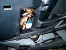
Brake Switch Visible thru Opening4975 viewsThe blue and white bit is the switch; the sort of gold appearing box,(it is really black), you will not see in your 3 as it is a Smooth Talker brand amplifier for my Blackberry phone antenna. This install is detailed in the SmoothTalker phone antenna section of my gallery.
One way to remove and install the switch is to lower the "horizontal" panel above the brake pedal as shown where the flashlight head is located. To actually remove the switch, you slide your hand thru the gap and rotate the switch clockwise 1/4 turn while watching thru the rectangular opening. Installation of the new switch is the reverse of above - 1/4 turn counterclockwise.
Before you remove the switch, note its orientation - horizontal with electrical wires to the left. That is the way it should look after replacement as well.
The second time I replaced the switch, I did it all thru the rectangular opening and did not remove the horizontal panel - that is experience helping out.
The knee kick you have to remove regardless. It is sort of hinged at the bottom so you just pull at the top and sort of rotate the knee panel and then pull upwards for two plastic "fingers" to clear the slots they reside in.09 May 2011
|
|

Switch is blue colour thing thru the rectangular opening.3177 viewsThe blue coloured plastic bit thru the rectangular opening is the brake light switch. The fist time, I found it easier remove the switch by dropping the horizontal plastic panel, (two screws), and then slipping my hand in and rotating the switch clockwise 1/4 turn. The second time, I was able to remove the switch thru the rectangular opening and did not need to remove the horizontal lower panel. Obviously, I had to remove the sloping knee pad panel, (note sort of hinged at the bottom so pull back from the top.)
Regardless, do not touch the brake pedal - just let it sit where it wants to. One has to first remove the angled knee pad panel that sits under the steering wheel. It can be pulled from the top corner at the door side. Pulling releases a pair of those U shaped metal clips that LR loves so dearly. You have to pull quite hard. The bottom is held by a couple of plastic fingers in a couple of slots so you pull at the top till the two clips release and then rotate the panel and pull upwards a bit.
To remove the switch, you rotate it clockwise and pull outwards. Rotating the switch clockwise automatically retracts the plunger back into the switch body away from the brake pedal arm.
Similarly when you install the new switch, the required 1/4 turn anti clockwise rotation action releases the plunger so it lays up against the brake pedal arm and at the same time, secures the switch in place.
To remove the electrical wires, the switch will drop below the horizontal pad and hang from the wires so unclipping the electrical connector plug is fairly easy to do.09 May 2011
|
|

Black Deposits to interior of Brake Light Switch2862 viewsThere are two contacts, one on each side of the vertical plunger under the copper metal. The set of normally open contacts on the left side that carries the power for the brake light filaments, (15 amp fuse F15P), is apparently not heavy enough as the contacts deteriorate and generate the black residue.
The set of normally closed contacts on the other side appear to be sized OK. There is not as much current, (5 amp fuse F66P), flowing thru the contacts to the ABS module, however the contacts are likely adversely affected by the black residue produced by the other deteriorating set of contacts.
One presumes/hopes that the newer replacement switch now has contacts heavy enough to carry the brake light power. It would be ideal if the ABS set of contacts were sealed from the brake light contacts to prevent contamination of the normally closed set of contacts. 09 May 2011
|
|

Black Deposits on Brake Light Switch Plunger2758 viewsThis jpg I got off another forum and is typical of what one will see when one opens up the removed brake light switch. The black powder is residue from arcing of one of the pair of contacts within.
Hopefully the newer switches with the FOMOCO logo moulded into the plastic are improved from the Land Rover logo marked early units, however I doubt it.
The Ford part number is SW-6572 and/or 7E5Z-13480-A as used on the 2006 to 2009 Ford Fusion's and Mercury Milan's; the Land Rover part number is XKB500110. Cost of switch could be about twenty five dollars. A previous LR part number for the switch was XKB500030, so hopefully the newer LR part number, XKB500110, reflects some improvement in reliability.
It is possible that the new switches are better as I installed a replacement 72,000 km, (45,000 miles) later, at 195,000 km (121,000 miles). When I took the removed switch apart to inspect, it was clean inside. There was no black dust - the switch looked like new, hence they must be improved now.09 May 2011
|
|

Land Rover Brake Light switch XKB5001102700 viewsThis is what the switch looks like when removed from the parts box. Note that the plunger is recessed back into the body and when installing, the process of rotating the switch body 1/4 turn anticlockwise releases the plunger so it pops longer and engages the brake pedal. If you look down on the plunger you can see curved slots where the rotation takes place.
Do not try to rotate the new one - play with the one you remove. Also do not press on the brake pedal when removing or installing as you will damage the plunger - this is one of the reasons the plunger is retracted into the body for installation. It is also for this reason that if you try to confirm the operation of the switch contacts with an ohm meter by pressing the plunger, the switch will appear not to function as one might anticipate. Have faith, the switch will however, once installed and the plunger is in full motion.09 May 2011
|
|

Stop Light Lamp Circuit pdf2492 viewsThis pdf shows the brake light circuit for the NAS LR3.
Note that power for the brake light bulbs can come either thru the brake light switch power feed /contacts plus also from the Hill Decent Control, (HDC), system relay located within the Central Junction Box, (CJB) - yes two separate sources of power for the brake light bulbs. This would tend to explain how a brake light circuit concern shows up as a hill decent fault message; also why lesser vehicles without hill decent braking mechanisms, (HDC), never display this sort problem when a brake light bulb or switch acts up. You never have a problem related to a system that does not exist.
Additional evidence of the relationship of the HDC and the tail light circuit is demonstrated by when the HDC actually acts to slow the 3 down, the brake lights automatically illuminate even if the slowing action was merely retarding the engine speed or shifting to a lower gear, (in other words, no foot on the brake pedal).
There is also a tie in to the Cruise Control and hence a failing brake light switch can affect cruise operation or just create false Cruise Control messages. To further complicate the issue, while there are no messages generated, operation of the radiator electro viscous fan can also be negatively affected by the fouled set of secondary contacts within the brake light switch. This is all because the NC contacts within the brake switch send misleading messages to the ECU.
While the ground wire design is similar to other vehicles, note the grounds for the brake light filament and the reverse light filament are common on each side. That means that if one has a non functioning brake light on one side, the reverse light may not also work or that some problem with the reverse lights could back feed into the brake lights. This situation while unusual, can result when grounds are corroded probably due to swimming in rivers and creeks or just routine driving in a marine environment.09 May 2011
|
|

Front Runner Y style rear tyre carrier 583 viewsThis is the new Y or D shaped Front Runner, (out of South Africa), brand of rear bumper mount tyre carrier.
The big deal is the new self latching mechanism.07 May 2011
|
|
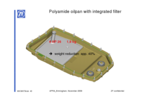
ZF_6HP26_Plastic_Filter_Pan_ combo.png1103 viewsThis is the plastic oil pan on the bottom of our ZF 6HP26X transmissions. Note the two round magnets at the right end of the pan; the drain plug is between them. The filter is the grey part and the vertical oil suction pipe is to draw oil up to the transmission from the filter element. There are 21 Torx screws around the perimeter and the pan gasket is O ring like in design where a half round channel is moulded into the plastic of the pan. The metal pan uses a more conventional flat gasket and in both cases, the metal mating surface of the transmission case is a flat machined metal surface.26 Apr 2011
|
|
ZF Plastic Pan / Filter part numbers852 viewsZF, not Land Rover, part numbers for the various types of plastic pan depending upon vehicle manufacturer. The BMW pan is apparently different from the Land Rover pan even though the transmissions are 6HP26 units. No wonder each manufacturer has his own oil - maybe it is different as well. What I find interesting is the mention of Ford Australia and Ford USA separately rather than just Ford. 26 Apr 2011
|
|

ZF Transmission parts exploded views1292 viewsA 35 page pdf showing exploded views of the inside of the transmission along with oil fill procedures and part numbers. There is also the suggestion of a metal pan but no part number given and the appearance of a more usual type of oil pan gasket, flat rather than O ring. 26 Apr 2011
|
|

ZF 6HP26 transmission fluid drain and refill procedure4040 viewsThis is the Land Rover instruction pdf and I note they have it right - that is remove the filler plug first, then the drain plug. Also before you attempt that, not only do you need oil, but also new fill and drain plugs as the sealing washers are deemed single use only.26 Apr 2011
|
|

ZF 6HP26 Land Rover Transmission specs1677 viewsThis is just two sheets of paper with various numbers related to the 6HP26 such as oil capacity, gear ratios, and torque wrench settings for the fill and drain plugs.
You may note that LR calls this ZF transmission the 6HP26 whereas ZF calls out the LR3 transmission as the 6HP26X. Just what the differences are, I am not certain however the X refers to 4WD or AWD use as opposed to solely 2WD.
Zahnradfabrik is what ZF is short for and translated from German, roughly means Gear Factory.26 Apr 2011
|
|

LR 6HP26 transmission oil part number TYK5000501420 viewsThis jpg shows the genuine Land Rover transmission oil, part number TYK500050, for the 6HP26X tranny. The Shell product number is M-1375.4 but you cannot buy the oil retail from Shell. The container size is one litre.
A routine oil change where the pan/filter combo is not changed takes about 3.5 to 4 litres of oil. When the tranny is brand new, a dry fill can take up to 9.5 litres of oil however around 7 litres is more common for when a new pan/filter combo is installed on an already in service transmission. 26 Apr 2011
|
|

Manufacturers brochure re plastic pan1035 viewsI found this ad from a German manufacture called LANXESS Deutschland GmbH saying that they manufacture the plastic oil pan/filter combo for ZF that is used on the 6HP26 six speed transmission.26 Apr 2011
|
|

LR3 Denso Alternator YLE500390 pulley view819 viewsNote the DENSO sticker on the side. Denso calls their nominal 150 amp 12 Volt alternator an SC2 design. SC means Segment Conductor which apparently increase the winding density of the stator coil, hence yielding a physically smaller lighter alternator for a given output. I presume the 2 means the second try at getting it right. A Denso part number is 4280003690 for the alternator, (there are others, as below).
Rotation is clockwise and the 54mm diameter pulley has 6 grooves (PV6x54). Count the pulley grooves on both the one you remove and your new one - some replacement alternators seem to ship with 5 or 7 grooves so you might be swapping pulleys.
A previous LR part number was YLE500190 for the older variation of the newer YLE500390 unit.
An additional part number for a factory rebuilt is Nippon Denso 210-0569 for the petrol V8 alternator. Other Nippon Denso numbers include 104210-3690 and 104210-3691. The Lester number is 11206 which relates to another Denso number of 290-5287. WAI uses 11206N.
From 2006 to 2009, the internal regulator is a Transpo IN6349 and of the B circuit type if it can be said that applies to PWM, (Pulse Width Modulated), regulators.
The "regulator" inside the alternator is therefore really not a regulator in the old sense of the term but instead an instruction receiver from the ECM that translates Pulse Width Modulated (PWM) signals into a form that the alternator understands – digital like signals from the Engine Control Module(ECM) into analogue like signals that the windings understand.23 Apr 2011
|
|

LR3 Denso Alternator YLE500390 rear view709 viewsThis picture shows the rear of the YLE500390, the Land Rover part number for a newer design alternator utilizing the Transpo IN6349 regulator with the "hidden" cooling fins. Note the visual difference in the rear view of the next file jpg.
If the alternator is a rebuilt, (service exchange unit), but Land Rover supplied, then the part number is LR008860 or similar. (Note that 0 in LR0 is zero.)
Two Denso part numbers exist for the alternator as well, 4280003690 and 4280003691. The rating of the petrol V8 alternator is nominal 12 VDC and 150 amps. In normal day to day operation, they seem to run about 14VDC - usually between 13.9 and 14.1 volts at the OBD port.
For the petrol V6, the LR service exchange number is LR008862, and the 2.7TDV6 is LR008861.
The bridge rectifier within the alternator is a 12 diode avalanche type, 117mm diameter, as used in Nippondenso 120 to 160 amp alternators with the Hair Pin stator. It is similar to a Transpo INR421 which is rated for 120 to 150 amp alternators. That is probably our primary problem - the rectifier is just too light. Alternate part numbers for the bridge rectifier are Cargo 237607, Mobiltron RM-29 and AS ARC6021.
Re the B+ stud, the INR421 calls it up as an M8 x 1.25 x 30 mm long course threaded stud; some say 34 mm but that may be longer than desirable. 23 Apr 2011
|
|
Replacement Bracket, LR part # RQU500064 for Air Compressor1026 viewsThis is a jpg of an aluminum replacement air compressor bracket, Land Rover part number RQU500064. The three rubber noise isolators are to be removed from the old bracket and inserted in the new bracket.20 Apr 2011
|
|
Air Compressor mounting bracket new907 viewsFound this jpg on a forum - thought it was good and is what one breaks when one jacks on the plastic air compressor cover.20 Apr 2011
|
|

LR3 Electrochromatic Interior Rear View Mirror wiring diagram.853 viewsIt seems that there are two fuses, F69P and F5P that provide power for the interior rear view mirror. Ten amp F5P is a feed off the reverse gear relay and inhibits auto dimming when reverse is selected. Five amp F69P provides power to the auto dimming circuits and the garage door opener function if optioned.
The pdf can be downloaded and printed out. For on screen viewing, right click on the pdf and select the Rotate Clockwise button.31 Mar 2011
|
|

Underside of ZF 6HP19 and 26 transmissions pans1429 viewsThis is a view of the underside of two different plastic transmission pans, one for the ZF 6HP19, and the other, the 6HP26.
The 24 Torx screw pan is for the 6HP19; the 21 Torx screw pan is for the 6HP26/28/32 transmissions. The screws are numbered in the order that they are to be tightened re the O ring seal. Our 3 has the 21 screw transmission, the ZF 6HP26X six speed.25 Mar 2011
|
|

Series LR at Oil Sands Plant in Northern Canada circa 1968747 viewsThis is an end of shift picture taken about 1968 at the Great Canadian Oil Sands (GCOS) plant while under construction in the Ft McMurray area of Northern Canada.
I was surprised to see the yellow coloured Series single cab hardtop pickup parked in about the centre of the picture. I would say it is one of the few on site as most vehicles were Chevrolet's, (as are the other three trucks elsewhere in the view). The yellow painted vehicles including the Land Rover are most likely Bechtel owned - not leased - yes, that long ago now.14 Mar 2011
|
|
Air Conditioner Drain Hose on Drivers Side (LHD)2297 viewsThe corrugated rubber bit above and to the right of the gas pedal is the drain hose that goes down thru the carpet and floor sheet metal.
While it is bit hard to figure out from the jpg above, there is a rubber "strap" attached to the top of the corrugated hose that one uses to pull on to drag the hose up back around the black plastic heater "pan" drain. The same drain hose arrangement is on the other side as well.
One could I suppose run a plastic snap tie around the vertical pull strap if one was concerned about the hose slipping off again. See also the other jpg sketch which is from the Land Rover manual.14 Feb 2011
|
|

NAS 7 Pin Round Socket + 4 Pin Flat Socket oriented as installed.752 viewsThis is the layout you see when you look into the NAS Land Rover sockets as installed at the rear of the LR3/4. The flat 4 pin socket is located under the round socket.
Wiring order is relative to the slot on the round socket, and hence the same as the other jpg where the slot is shown at the top.
The CJB monitors the front and rear turn signal lamps and can detect if more than four lamps are fitted, (the side turn signal lamps are not monitored). This is another reason for using genuine LR bulbs as off shore bulbs can have varied and out of spec resistance values.
When a trailer is detected, the trailer warning indicator in the instrument cluster is supposed to flash green in synchronization with the turn signal indicators.
If one or more of the turn signal lamps on the vehicle or the trailer are defective, the trailer warning indicator will cease to flash any longer. This is to alert the driver to probably bulb failure.
If the trailer has LED lamps installed, and no LED adapter circuitry is used, most likely the trailer will not be sensed and systems such as the backup sensors will not be disabled.13 Feb 2011
|
|

NAS 7 Blade Round plus NAS 4 Pin Flat Vehicle end Socket528 viewsThis shows the function of each blade when looking into the connector at the vehicle end for the 7 pin NAS plug. The layout is the pin order for most new North American pickup trucks and the LR3/4.
The colour and gauge of the wires feeding into the back of the plug varies even within manufacturer model lines.
Also detailed is the flat 4 pin layout common on smaller trailers not having electric brakes. This includes most U-Haul rental trailers.12 Feb 2011
|
|

Air Suspension System Parts, Layout, and Operation7062 viewsThis 22 page pdf gives a pretty good description of how the system is supposed to work, plus shows the various parts and the electrical including fuses and relays etc. Of the files here, this is the most useful.
As with all the pdf's here, you can download and print it out.10 Feb 2011
|
|
John Guest DOT all plastic fitting718 viewsThis is a picture of the John Guest DOT all plastic union. If you look closely, you can see the DOT imprinted in raised letters on the end of the fitting. This is of a 1/4" connector rather than the 6mm that the 3 requires.
The picture is similar to the air suspension pneumatic fitting union that Land Rover sells as replacement part # STC8580. This is for 6mm OD tubing size. The STC8580 comes with what are called "Collets" at each end that cover up the press to release feature underneath. See the John Guest web site www.johnguest.com under the Pneumatics section and also in Downloads for their catalog for install and remove instructions.
The actual "air brake spec" fitting that Land Rover provides has an interior 4mm OD ferrule that slips inside the 4mm ID of the nominal 6mm tubing. I have not yet been able to obtain the John Guest part number for the LR fitting, only the LR part number. This part number was generated for the RR Classic air systems.
25 Jan 2011
|
|
Detroit Fluid DOT air line fittings718 viewsThe picture shows the internal ferrule that is characteristic of the DOT / TUV accepted fittings for highway vehicles. Most often these fittings are metal however the Land Rover John Guest 6mm straight connector is all plastic and has the internal ferrule.25 Jan 2011
|
|

NAS 7 plus 4 pin LR3 Trailer wiring, battery end. 549 viewsThis is the LR wiring diagram from the engine compartment battery location to the Electric Brake Controller connector, C2590, located under the dash near the brake pedal.24 Oct 2010
|
|

NAS 7 plus 4 pin LR3 Trailer wiring, trailer end. 498 viewsThis is the LR wiring diagram showing the conductors from the the Trailer Brake Controller connector, C2590, back to the rear combo NAS 7 plus 4 pin sockets.24 Oct 2010
|
|

LR Electric Trailer Brake C2590 Female Connector606 viewsThis female connector, C2590, located up above and near the brake pedal is for the Trailer Electric Brake Controller hookup.
The Black wire in the bottom right is pin #3, the ground. The Blue wire to the left is pin #6, the Trailer Brake Controller output going to the rear trailer socket.
The White #4 wire is the 30 amp fusible link, (Link 6E in the engine compartment junction box), for the Brake Controller 12VDC power feed from the battery. Note that this would make a pretty good power source for CB radios and the like if no electric trailer brakes were required.
Pin #5 is a Green wire from the stop lamp switch, (the control input for the Brake Controller).
This plug is standard on all NAS (LR3) vehicles, but unlikely to be found on the D3 spec units.24 Oct 2010
|
|

Tekonsha Ford Brake Controller Adapter part number 3035-P275 viewsThis is the adapter cable between the Brake Controller and the existing C2590 female plug located near the brake pedal on NAS spec LR3's. The flat 4 pin plug of the adapter cable connects to the Controller; the rectangular 6 hole male plug to C2590.
There are only four conductors in the adapter cable, but one will see five pins within the Land Rover C2590 plug. The #2 pin is not required for the NAS setup. #2 pin is the circuit between the head lamp switch and vehicle side running lamps required in the civilized world.
The single pin at the bottom in the picture is #3 and on the Land Rover, a Black wire tied to ground. The other pin at the bottom and across to the left is #6, and Blue on the Land Rover. This is the Brake Controller output to the trailer socket at the rear.
#4 is the pin at the top left, and is a White coloured wire from the battery. Pin #5 is from the stop light switch, and is Green on the Land Rover.
Note that the adapter cable colours do not necessarily follow all the above referenced Land Rover colours.24 Oct 2010
|
|

Curt Manufacturing Installation instructions Class III345 viewsThese are the instructions for installation of the Curt Hitch.22 Oct 2010
|
|
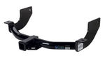
Curt Manufacturing brand hitch, assembled but not installed.290 viewsThe Curt Manufacturing hitch is an alternate to the Land Rover removable "plow" hitch. Once bolted in place, the Curt hitch is always there.
The Curt part number is 13456. It is a Class III hitch with a 2" square receiver and designed for a maximum 600 pound tongue weight.
The hitch hangs below the rear bumper but does not stick out past the bumper; also the "donut" spare tyre can still be installed / removed; am not so certain about a full sized fully inflated spare.22 Oct 2010
|
|

Tekonsha P3 Brake Controller 90195 to Ford 3035-P wiring adapter plug311 viewsThis two page pdf is the general instruction for hooking up the Tekonsha part number 3035-P adapter cable between a Tekonsha P3 controller and the existing Land Rover/Ford plug, (called C2590 in the Land Rover wiring diagrams), that is hidden above the brake pedal.
The "Ford" plug, (C2590), is grey and is stuffed up above the brake pedal arm.
Mount the P3 controller appropriately and then connect one end of the custom cable to the P3 and the other to the "hidden" plug.
You will now have power for your trailer electric brakes in the round socket at the rear of your LR3; also no computer update from the Land Rover T4 unit is required. For once, it is plug and play.
If however, your trailer has LED tail lights, you may have trouble with the flashing of the trailer signal lights or non recognition by the 3 that a trailer is connected. As such, the little green trailer signal will not illuminate when a trailer is connected and the signal lights are used. This can affect the shifting of the transmission and much to your annoyance, the backup sensors will still be functioning rather than being auto disabled.22 Oct 2010
|
|

Tekonsha P3 Electric Trailer Brake Controller model 90195291 viewsOne model of electric brake controller that is commonly used on the LR3 is the Tekonsha P3 unit, model number 90195. It mates up to the LR3 with a custom "Ford" adapter cable, Tekonsha part number 3035P. No wire cutting or splicing is necessary - just mount unit and plug adapter cable in.22 Oct 2010
|
|

LR3 and 4 NAS hitch receiver original and newer third generation.774 viewsThe picture shows the original 2005 model "plow" for the LR3 and the newer shorter hitch receiver introduced with the LR4. Either receiver can be used on the LR3/D3; they are interchangeable.
The part number of the newer third generation short style is LR019990 replacing previous long type part number KNB500080. There were two versions of the longer one, KNB500080 with the orange key, apparently a better locking setup. The first generation, KNB500023, with a black key was less than perfection.
The green lock assembly with orange key, part number KNW500010, shown on the shorter hitch, can be purchased separately should a key be lost.
Regardless of receiver model, the receiver will accept nominal NAS 2" tongue on which may be mounted the appropriate ball size. 22 Oct 2010
|
|

NAS Trailer Wiring Colour Code366 viewsThis is a common wiring colour code for trailer wiring in North America. Some vehicle manufacturers follow the code for at least some of the functions.21 Oct 2010
|
|
4 pin NAS flat connector from NAS small trailer382 viewsThe connector with the three exposed pins is the end that would commonly be located at the trailer hitch end, (front), of a small NAS lightweight trailer that has no electric brakes. This plug would connect into the flat 4 pin connector at the rear of the 3.
Note the order of the pin functions and wire colours: White is ground; the next pin is for tail/marker lights using the Brown wire; the Yellow conductor is for the left turn signal, and the far pin uses the Green conductor for the right turn signal.
There is no separate brake light conductor as NAS spec vehicles most often combine the brake and signal light functions to the same bulb filament rather separate filaments in different bulbs. The LR factory harness resolves that design difference.
Fortunately, the Land Rover NAS assembly pin order for the 4 pin flat plug maintains the above described conventions. 21 Oct 2010
|
|
NAS 7 pin + NAS 4 pin Flat Trailer Socket308 viewsThis is the vehicle end of the NAS trailer harness that is located behind the removable plate centered within the rear bumper by the towing loop. Re the four pin flat connector, from the bottom, the exposed bare lower pin is the ground, usually the White wire on a NAS trailer. The next pin up is normally a Brown wire on a trailer and is for the Tail Lights. The third pin, normally a Yellow wire, is the left signal light; the top pin, normally a Green coloured wire, is the right signal light.
Re the round connector, from the notch in the plastic surround, clockwise, the first blade is ignition controlled +12VDC battery power, (only alive when engine running), and on the Land Rover factory harness is an Orange wire; on a NAS trailer, usually Red but perhaps a Black wire.
Next blade clockwise at 3:00 o'clock above, is the Right Turn signal light, a Green wire on the LR harness, and also on a NAS trailer.
At 5:00 o'clock, the next blade is for the Electric Brakes and is Blue on both the LR harness and on a NAS trailer.
The Ground wire is next, White on both the LR harness and on a trailer.
At 9:00 o'clock above, is the Left Turn signal, Yellow on both the LR harness and on a trailer.
The last blade to the left of the line up notch is the Tail Light circuit. On the LR harness, the wire colour is Brown with two White stripes and on a NAS trailer, Brown.
The centre pin is for the Reverse Back Up lights and is Black on the LR harness and often Purple on NAS trailer wiring but can be Black also.
Note that when the socket assembly is installed on the 3, the notch in the plastic surround is on the left - that is rotated 90 degrees anticlockwise to the picture above. In other words, When installed on the 3, the 4 pin flat connector lays horizontal and is located below the round socket.20 Oct 2010
|
|
Harness section that runs behind the rear bumper.410 viewsThis is the harness section that clips up inside the rear bumper and includes the circular 7 pin, (6 flat +1 round), NAS socket, and also the 4 pin NAS flat connector.
The two small plug ends connect under the rear left tail light to the harness section that exits from the interior.
The Land Rover part number for the NAS trailer tow kit, (both cables), is YWJ500220.20 Oct 2010
|
|

Harness that connects inside left rear compartment.445 viewsThis is the harness section that connects behind the left rear interior access panel and exits thru the large grommeted hole to below/behind the left rear tail light.
Note the two rubber grommets on the harness as there is both an interior metal skin and an exterior metal skin behind the left tail light assembly.
The two light grey connectors plug into two existing connectors near the top of the rear left interior access panel. The two darker connectors plug into the second piece of harness.
There is no little separate fuse box either with the NAS spec harness. The fuse box is included with the UK 13 pin dual plug units. If there was a fuse box, it would be on this portion of the harness.20 Oct 2010
|
|

LR3 Air Conditioner Drain Tubes behind centre console2132 viewsThis shows the two air conditioner drain tubes located left and right under the radio stack.
The tube on the left side, (steering wheel side, LHD), disattached itself and the carpet on the floor under the gas pedal etc became soaked. I think rain water from outside that comes in the outside cowl vents also exits via the tubes as I first noticed the carpet was wet after parking outside during a big rain storm.
It was relatively easy to slide up and reattach the rubber hose that runs from the rectangular shaped plastic discharge hole(s) of the heater "pan" down along the transmission hump area and thru the floor pan. There is a hose on each side of the transmission hump, but only one hose had let go on my 3. The rubber hoses just slide over the rectangular plastic openings of the two heater housing drain outlets.
To get at each drain hose, remove the vertical sort of triangle carpeted piece below each side of the radio stack. The triangles of carpet will just pull away as each is held on with those metal U clips Land Rover so likes. Dislodge each triangle at least sufficiently to get ones hand in to slide the rubber hose back on.
You will rarely see AC water on the ground as the front drains pour onto a metal underside protection skid plate and the rear drain onto the top of the left rear muffler.18 Jul 2010
|
|
Reservoir Air In fitting installed 1661 viewsSchrader valve installed. Shop air can now be introduced into the tank to facilitate the raising of the 3 when there has just been a failure of the onboard air compressor rather than the electronics or valve block wiring etc.
Air could also be sourced from this point, however the purpose of the modification is air in, not air out as the air pressure normally runs above 200 psig, too high to be safe for routine use unless a pressure reducing regulator is added per the Mitchell Bros kit.30 Jun 2010
|
|
Reservoir Air In fittings exploded view 1893 viewsThis shows the fittings required for the mod. The reducer adaptor requires a 27mm socket and is M20 x 1.5 male thread x 1/4" NPT female. The 1/4" male NPT Schrader valve has the standard valve core removed and an AN/MIL spec aircraft oleo strut valve installed instead.
A standard automobile valve is rated at 200 psig, (14 bar); the air tank runs closer to 244 psig, (16.8 bar), with the relief valve set to open between 334 psig, (23 bar) and 370 psig (25.5 bar). The aircraft valve is rated at 2,000 psig, (138 bar).
30 Jun 2010
|
|
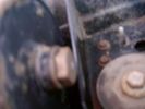
Reservoir Bung 24mm socket 1155 viewsThis is the view of the air tank at the end nearest the front left wheel. This is what you see before you do the mod. The other view is after the mod.
On pre 2008 models, there is this 24mm socket hex head bung, M20 x 1.5 thread, that can be unscrewed and the Schrader valve assembly installed instead. On newer 3's the bung hole was deleted from the front end of the air tank; hence the mod as described, is then not possible.30 Jun 2010
|
|
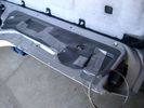
Dust Seal duct taped back together 2281 viewsThis shows the dust seal duct taped back together; also the surplus wire rope exiting from the actuator area prior to being cut to length.
I do not think the sticky plastic membrane is a dust seal, but more of a cable protector to cover up the wiring bundle that is effectively sticking to the underside of the flexible membrane.22 Jun 2010
|
|
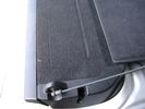
Flexible wire rope fishing leader 0.032" diameter exiting carpet 1949 viewsThis is all you see of the completed mod.
The short little angled "line" about an inch long that looks like a piece of debris and is located a few inches "above" the support cable is actually the wire rope release cable exiting from under the carpeted lift gate cover.
I drilled a very small hole in the carpet and pushed the 0.032" diameter release wire thru and then slipped the loose end under the black plastic.
To release with the lift gate etc closed, from the inside, just pull the loose end free from under the black plastic and gently pull wire about 5mm, (1/4"), and the upper door catch should release. You will have to manually push the upper door out wards to actually effect opening, but you will already be inside the rear cargo area so that part is easy to do.
The assumption is that the lower door latch still works electrically and hence, the lower lift gate half will open as normal by pressing the usual button on the top left of the lower door half. 22 Jun 2010
|
|
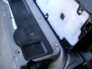
Carpeted cover removed showing uncut dust seal and underside of carpeted cover. 1628 viewsNote that there are all sorts of electrical wires sticking to the underside of the dust shield - so be very careful when you cut thru the shield.
I used a box knife very slowly and was surprised at how many conductors there were running just under the shield membrane.22 Jun 2010
|
|

Carpet Panel Removed showing Bass Speaker and Dust Shield 1734 viewsSomething is wrong with the orientation, however this shows what you see when the carpet is removed.
The dust shield, (under which the actuator is located), in the picture is as yet uncut. The white bit is the underside of the plastic lower lift gate carpeted cover panel.
The round thing is the woofer speaker for the Harmon Kardon radio. When the radio is working, one can see the speaker moving, but not much bass sound actually seems to emanate from the speaker.22 Jun 2010
|
|
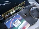
0.032" OD metal fishing leader and lead fishing weight clamped to existing wire rope 2121 viewsI used a size #0 lead fishing weight as a clamp to attach the 0.032" diameter flexible wire rope fishing leader to the release cable.
The pictured weight is the smaller #00 weight, however it did not work very well so reinstalled with the larger #0 size. I clamped to the cable as what breaks is the L retainer that is hidden in the actuator and holds the cable. When the L breaks, it lets go of the cable so you hear the clicking but there is no opening action.
Clamping on to the cable is an attempt to resolve that reality; also if the actuator electrically fails, the release mod should still do the task. Note in the picture the two Torx T15 screws that hold the gold plate to the plastic case and also the two 8mm cap screws that have to be loosened to remove the actuator from inside the door.22 Jun 2010
|
|
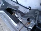
Dust seal rolled back showing electrical conductors 1658 viewsNote power conductors just under the dust seal which makes cutting the seal more interesting.
Also shown are the two 8mm nuts located in slots. One must loosen each nut to effect removal of the actuator. This will then reveal two T15 Torx screws that one must completely un-thread to remove the top gold plate from the actuator assembly.22 Jun 2010
|
|
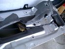
Dust seal cut; note electrical conductors right under dust seal 1627 viewsShows what is underneath when the dust seal is cut. Note the electrical conductors.
I used a box knife to cut the plastic and it was at first easy; then I seemed to hit something and fortunately I stopped - it was the wires - lots of them stuck right to underside of the sticky seal material.
Also shown are the two 8mm nuts in slots that you only have to loosen to release the gold actuator assembly.22 Jun 2010
|
|
![Filename=Technical Service Bulletin SB034 SB036 Vehicle Enhancement Program[1].pdf
Filesize=959KB
Dimensions=0x0
Date added=17.Jun 2010 Technical Service Bulletin SB034 SB036 Vehicle Enhancement Program[1].pdf](images/thumb_pdf.jpg)
Technical Service Bulletin SB034 SB036 Vehicle Enhancement Program2390 viewsOn page 6 and following are the Land Rover service bulletin instructions as to how to install delivery valve and exhaust valve repair kit JPO500010; also a list of previous compressor model numbers as related to the 3. The new delivery valve is easy to install, the exhaust, not so easy. Note that this in not the more recent TSB that reduced the operating pressure of the compressor via a software fix and also recommended replacement of the air compressor 70 amp relay. See the F35 album near the bottom for the relay material.17 Jun 2010
|
|
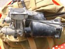
Compressor Air Drier 2044 viewsA view of the air drier - the black round thing to the right of the actual compressor cylinder head.
The general feeling is that the air dryer is responsible for most of the compressor problems now and that replacement of either the assembly or just the beads inside will probably revive one's compressor. In reality, the beads may have for the most part broken down and turned to dust plugging the internal filters. Hence replacement of the complete dryer unit has some merit.
The part number for the dryer assemble complete with the desiccant is VUB504700.15 Jun 2010
|
|
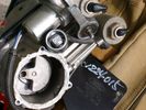
Compressor Exhaust and Inlet 1534 viewsThe two temporary black plugs cover off the 8mm and 10mm push fit lines to the air inlet and exhaust lines. Also visible is the worn threaded stud that I think was the initial failure mode.
15 Jun 2010
|
|
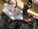
Compressor Electrical Plugs 1406 viewsThis shows the two electrical connectors; the two pronger is the power to the compressor, and the multi-pin connector carries control signals. Also the temporary red plug is where the 6 mm tubing from the centre valve block connects. This line carries both the compressor and exhaust air to and from the springs.15 Jun 2010
|
|
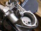
Compressor Con Rod Stud 1342 viewsVisible in the expanded view of this picture is the worn rounded threaded screw that tied the con rod bearing to the electric motor eccentric. I think the stud unscrewed itself and pulled out; then the piston jammed and the con rod broke.15 Jun 2010
|
|
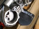
Compressor Con Rod Broken 1753 viewsThe model number of this compressor is RQG500060; the model number of my replacement compressor was LR015303, the unit that was apparently being installed on the D4 vehicles as of Spring 2010. As of Fall 2011, the new replacement part number is LR023964, the same as in the 4's.
Note the number hand written on the black plate. All the compressors seem to have some number hand written on them - hand built I presume, and every unit perhaps evolving a bit differently as LR struggles to build a compressor that will last. I guess Hitachi, (the manufacturer), should be given credit for that.15 Jun 2010
|
|
Battery Disconnect side post with + & - caps under view743 viewsThe upper and lower pieces of metal are clamped together but electrically seperate from each other. The connection between the two pieces is via the threaded part attached to the knob. When the knob is turned tight, current will flow between the two sections of metal.08 Jun 2010
|
|
Battery Disconnect side post with + & - caps, top view617 viewsThis disconnect is designed for side post batteries. It can be used on either the + or - terminals. It can also be installed at the "other" end of the battery cable as well. In my install of the Aux battery, I installed this on the negative ground cable where the cable attaches to the body sheet metal. I have never used it but it seemed like a good idea at the time. The main battery hookup is pure stock.
For the hot side of the Aux battery, an Anderson PowerPole was used inline for the cable between the Aux and connecting to the spare bolt hole at the + post of the Main battery cable.08 Jun 2010
|
|
Battery Disconnect Wirthco 20308 Knob Top Post 890 viewsThis is a battery post style disconnect, usually for the negative terminal. There is a hole drilled in the round end off the battery so that flat terminal can be attached as well as the normal battery post terminal. I did not use this hookup arrangement, however I show it for information only.08 Jun 2010
|
|

Voss System 203 Connector cut thru, (similar to in valve block).678 viewsThis is a cut thru of a Voss System 203 connector. The top third of it is similar to the connector that holds the three 6mm plastic tubing lines into each of the front and rear valve blocks.
I say top third, as per the other pictures, the 3 has a Voss assembly that threads into the plastic of the valve block, whereas in the cut thru above, the Voss brass assembly is threading into the brass body of a metric threaded adapter for threading into a standard type metric threaded hole. Note also the two one way sloping ridges of the cutting ring, and the two interal O ring seals that mate with the plastic tubing. There is additionally the small squashed O ring to provide a seal related to the external thread of the Voss cutting ring assembly; (similar to the larger O ring for the brass body external thread).23 May 2010
|
|
Voss System 203 connector 6 mm for valve blocks 906 viewsThis is Land Rover part number RQC000030, the Voss fitting for the axle valve blocks. I think it is a Voss System 203 6mm fitting, Voss part number 5 2 03 11 01 00.
The parts bag comes with the white plug inserted in the brass threaded bit with what is called the brass cutting ring placed on the tip of the white plastic plug. The idea is that one screws, (M10 x 1 thread), the brass insert into the appropriate hole with the white plug still in the brass insert. Once the brass is tight, (12 mm wrench), then the white plug is pulled from the assembly leaving the cutting ring down inside and under. One then pushes in the 6 mm tube end about 20 mm or so and the tube slides down thru the brass cutting ring, (2 internal sloped one way cutting ridges). When the tube is in far enough, one pulls upwards a bit and the ring cuts into the plastic such that the tube will not pull out. To remove tube, one unscrews the brass nut and all comes out, sort of like I have shown with the short piece of 6mm tubing. The white plug is a throwaway item upon install of the tubing.19 May 2010
|
|
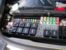
Picture of the engine compartment fuse panel5780 viewsEngine compartment fuse panel located near the battery. This is where F3E, (5 amp), F26E, (20 amp), Fuseable link 10E, (60 amp) and Relay 7E, the now upgraded 70 amp air compressor motor relay, part number YWB500220, (E is for Engine compartment fuse box), are all located. Fuse F35P, (5 amp), is inside the Passenger compartment behind the lower glove box door.
To keep the suspension from going down to the stops when driving, (or parked), it appears that it is only really necessary to remove F26E to depower the exhaust valve and generally keep all the valve block solenoid valves in a closed position trapping whatever air is within the air springs. F3E gets its power thru F26E, so when F26E is removed, the F3E circuit is automatically de-powered. F35P is more interesting in that battery power goes thru the ignition switch and F35P and then into the air suspension control unit. Apparently however, if F26E is removed, removing the F35P is not needed even when the engine is running.
With all fuses still in, if you have a problem, in practice, ideally, the compressor still works and will raise the 3 to an appropriate height. If so, one can then shut the engine off and allow the computers to go to sleep and then you remove the fuse(s). In actual practice, it seems that one need only pull the F26E fuse and can do so with the engine running. All the same, one might consider that the 3 is first a mobile computer, and secondly a 4x4. Computers prefer to go to sleep before the plug is pulled on them, however given that F26E circuit is always alive, then the computer never sleeps. With the fuse(s) pulled, and if you are still up, you can now be a 4x4 instead of a low rider. The whole purpose of the fuse pulling exercise is to depower the one and only system exhaust valve that is physically located within the compressor unit, (to keep it from opening), and secondarily to keep closed the four air spring solenoids within the block valves. This also shuts the air compressor down and stops the air compressor from making air even if the compressor is still good. That is why you initially need the fuse(s) in to allow the compressor to make air if it can.15 May 2010
|
|

Underhood Fuse and Relay Box drawing 3055 viewsShows the various fuse and relay locations. Fuse 3E, (5 amp), and Fuse 26E, (20 amp), as well as upgraded 70 amp Relay 7, part number YWB500220, locations are displayed. Relay 7 sends battery power to the compressor from the 60 amp fusible link called up as 10E. Fuse 26E is what provides full time always on battery power to the air suspension ECU and hence powers the auto level wakeup when the vehicle is shut down and say parked for the night. Removing F26E is the primary method to disable the air suspension system; Removing F35P is more if you want to experiment with it from inside.
I found it useful when I had a suspension problem, (actually a wheel alignment problem picked up by the steering wheel angle sensor), that only showed itself on the highway but allowed for no trouble light driving in the city. This was because in the city, the steering wheel was always in motion and rarely was the vehicle driven in a near straight line for very much distance.15 May 2010
|
|

Voss B203 Fitting Install957 viewsNote on the first page, the reference to DIN 73378 and D74324 and also PA11 and PA12 material when referencing suitable spec nylon (polyamide) air line for motor vehicles. I think some of the 6mm fittings used on the 3 for the valve blocks are the System 203 type and called up as Land Rover part number RQC 000030. The Voss part number is I believe 5 2 03 11 01 00.
05 May 2010
|
|
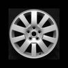
LR3 Sparkle Silver 10 spoke Wheel Cromodora of Italy 18 inch x 8 ALY72190U727 viewsThese wheels are factory standard on the 2005 LR3 SE and Made in Italy by the Cromodora company. Each wheel is rated at 940 kg (2,072 pounds) and has an offset of 53 mm positive, (53P or +53).
I mention the 940 kg load rating as that is about the heaviest rating of any Land Rover product. The RRS and RRHSE both have lower ratings. What this means is that while a wheel from a Range Rover may physically fit, it probably does not have the brute strength of the factory spec Land Rover 3 wheel. There is no Land Rover product heavier than the 3, hence the 3 wheel design spec is the heaviest of the bunch. 03 May 2010
|
|

LR3 Sparkle Silver 6 spoke Wheel Cromodora of Italy 19 inch x 8 ALY72191U1108 viewsThese are the standard equipment 19" wheels on the 2005 LR3 HSE. The wheels are Made in Italy by the Cromodora company. Each are rated at 940 kg (2,072 pounds) and have an offset of 53 mm positive, (53P or +53).
I mention the 940 kg load rating as that is about the heaviest rating of any Land Rover product. The RRS and RRHSE both have lower ratings. What this means is that while a wheel from a Range Rover may physically fit, it probably does not have the brute strength of the factory spec Land Rover 3 wheel. There is no Land Rover product heavier than the 3, hence the 3 wheel design spec is the heaviest of the bunch. 03 May 2010
|
|
CounterAct Power supply mounted under brake lines.194 viewsThis top view shows where I located the power supply. It is attached with 3M sticky to the black plastic surface that is located under the brake lines.
When the system is operating properly, the red LED pulses about twice per second.
Some users claim they can hear a very slight hum or whine coming from the unit. My unit seems silent.19 Apr 2010
|
|
Front Coupler pad to right front under air filter housing 156 viewsThe brighter white "square" behind the black air cleaner drain is the Coupler Pad location I chose for the right front corner. The 1/4", (5mm), black wiring loom carries a single blue colour conductor between the power supply and pad.
A second coupler pad, (white conductor), is located near the left rear tail light. The mounting location is accessible from the rear compartment access "door" where the trailer hitch wiring attaches to the factory loom.19 Apr 2010
|
|
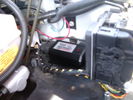
CounterAct Power Supply mounted 247 viewsPicture is blurred, however power supply is 3M two sided tape to the flat black plastic of the second battery compartment just under the antilock brake pipes to the fender side of the brake fluid reservoir. The white wire to the left rear coupler pad runs thru the firewall hole near the steering column. The blue wire to the right front coupler runs across and above the engine following the other wiring looms that cross the vehicle. 18 Apr 2010
|
|
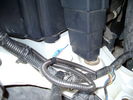
Front coupler pad to right front under air filter housing 160 viewsCoupler Pad is attached to the flat metal surface just behind the rectangular drain off of the air filter housing. The last 3 inches (75mm) of the 1/4" (5mm) black flex wiring loom was then threaded over the last bit of wiring. One of the other jpg's is less washed out and shows the coupler pad a bit better.18 Apr 2010
|
|
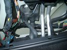
Rear coupler pad located near rear left tail light 144 viewsThe rear coupler pad is not visible as it is located "below and behind", so to speak. Follow the loop of black plastic wire loom from right to left as the loop of loom covering the white conductor wire drops down "behind" to the flat metal surface the pad is glued to. The pad is attached to the flat metal surface via a 3M sticky on the backside of the coupler pad. 18 Apr 2010
|
|

CounterAct LT-2 Install Instructions173 viewsThese are the instructions for installing the CounterAct coupler pads (2) and the power supply.18 Apr 2010
|
|
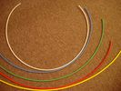
6mm Heat Shrink colours 362 viewsI decided to colour code the tubing so I used 6mm electrical heat shrink.
As there is no apparent colour coding re the 3, I tried to emulate the P38 coding; #1 LR red, #2 RR blue, #3 LF yellow, and #4 RF green. This was not doable as both left side air springs have green coloured tubing coming off the top of the front and rear air springs. I therefore arbitrarily chose the Left Rear to be red; Left Front green; Right Front yellow; Right Rear blue; and for the air compressor supply line, White coloured heat shrink. Since two new lines tie into each air spring line, I made the line between the air spring and the FASKIT, a single solid colour, and the line from the FASKIT to the valve block, White, plus the related appropriate solid colour.14 Apr 2010
|
|
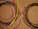
6mm PA12 grade nylon tubing with heat shrink applied 544 viewsShows some of the 6mm air line with heat shrink applied to one end of tubing. Shrink will be applied to the other end once field cut to length. These four tubes, each about 20 ft (6m) long, feed to the rear. Re the front air lines, (not shown), four additional lengths, each about 10 ft (3m) long, are required plus one more 3 metre length for compressor air. The 6mm tubing is a Nylon product specified as PA12. There is also a very similar Transport grade PA11 material, however it seems that PA12 is the more common Transport grade now in use. Also the applicable DIN standard seems to be both DIN 73378 and DIN 74324 for the nylon tubing. The working pressure of the 6mm tubing is about 27 Bar and bursting 82 Bar @ 20C. This is for the 1mm nominal wall thickness material, (4mm ID, 6mm OD).14 Apr 2010
|
|
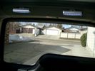
Boot lighting, looking to rear - hatch closed 543 viewsView shows the lights mounted in the rear on an early spring day.
In operation, the lights are tilted so that they shine downwards. The lights are mounted high enough up that one cannot see the LEDs from the front thru the rear view mirror; also the LEDs are so directional, that no light is thrown on the side glass.
Each assembly contains 15 LEDs, however the reflector is such that the LEDs appear to double.05 Apr 2010
|
|
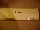
Boot lighting panel, finish side up 310 viewsThe above jpg shows the two 15 LED light assemblies as well as the SPST rocker switch mounted beside the W5W Land Rover supplied light.
The reality is that with the recent development of LED lighting that can replace a W5W T10 bulb, one can almost achieve the same results just by installing a LED bulb within the factory light.05 Apr 2010
|
|
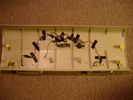
Boot lighting panel, wiring side up 282 viewsThis shows the back side of the plastic cover panel on which the two LED lights are mounted.
Also of note is the SPST rocker switch to switch the new lights off independent of the the Land Rover W5W light.
The new light pair will only power up if the Land Rover light is powered and hence dims and automatically goes off along with the Land Rover light.
The Black wire is ground, the Purple wire is +12VDC.
05 Apr 2010
|
|

LLumar AIR80 Air Blue 78 windscreen film IR reduction metal oxide341 viewsThis pdf summarizes the characteristics of the various types of window glass film available from LLumar. www.llumar.com
I had the Air 80 metal oxide sort of clear film, (windshield film they call it), installed on the front driver and passenger side windows to reduce the Infra Red penetration and hence heating effect on the front occupants. The film is barely visible from either inside or outside, however there is a noticeable reduction in heat penetration when sitting inside. In short, my arm does not get cooked.
Cell phone and GPS etc seem unaffected by the metal oxide film.
I also had the film installed on the three sun roof portions as well.02 Apr 2010
|
|

Littelfuse Add-A-Circuit MINI and ATO style data sheet150 viewsPDF from Littelfuse showing both the MINI and ATO style of fuse holders. The 3 uses the MINI size of fuse. The MINI Add-A-Circuit can be inserted in place of one of the existing fuse panel MINI fuses. The removed fuse is then inserted into the lower slot of the Add-A-Circuit and a second fuse in the second slot to protect the device that you are adding. The Add-A-Circuit is designed for a max of 10 amps on the second load, and I guess maybe the original circuit as well. 31 Mar 2010
|
|
Main Battery showing aux cable feed running off positive battery post.776 viewsThe black wiring loom around the battery cable to the aux battery was a part provided with the Traxide kit. My goal was to run the cable low enough such that the battery box cover would go back on as previous.
Note the hole drilled in the side of the battery box such that the new cable could thread thru to allow the battery box top to still fit the same as prior to the addition of the cable to the auxiliary battery.30 Mar 2010
|
|
Aux Battery showing ground cable bolt "upside" down 1577 viewsIn order to obtain sufficient height clearance to get the plastic cover back on, I had to install the ground cable to the underside of the battery post connector.
Note the battery vent hose, (approx 5 ft required) is run down into where the windshield washer fluid container is located. There is not much electrical or metal in that area to be corroded by battery gas plus the open end of the vent hose tends to be protected from dirt and stays clean as well.30 Mar 2010
|
|
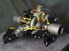
Rear Differential cutaway with E-Locker 1210 viewsThis jpg is from the link below.
There are another ten or so cutaways plus a whole file group showing a 2005 LR3 sectioned for the 2005 Chicago Auto show. Each jpg has an enlarge function to the bottom right of a main picture.
On one jpg you can see right into the stepper motor.
http://www.cutawaycreations.com/cutaways.php?project=land-rover-electronic-rear-differential#/IMAGES/car4/images/image1.jpg
Both the front and rear differentials are manufactured by Dana Spicer in the UK. Dana calls them a Clamshell design. 23 Mar 2010
|
|

Fin cell phone aerial drawing190 viewsThe factory aerial for the factory NAV / GPS on my 2005 HSE is within the high mounted stop light lens at the top of the upper hatch door. I do not have the factory installed phone kit, and as such, do not have the fin installed; instead there is just a plastic blanking insert to fill the cell phone aerial wiring hole in the metal portion of the roof; hence this requirement for an "external" cell antenna. For those that do have the fin on their glass roof, the fin is screwed on to a glued on plastic gasket, (sort of), and not bolted thru as per the metal roof 3's.23 Mar 2010
|
|

Battery Maintainer pigtail sticking out of Grill728 viewsThis is all you see when everything is put back together - just the pigtail and Weather Pack blanking plug. Most often, I have it all tucked back behind the grill.
In winter, there may be a second cord hanging out as well - the 120 VAC power cord for the engine block heater, a tea kettle like element inserted in the engine block. NAS petrol V8's do not have the Fuel Burning Heater, (FBH), installed, but instead in cold area markets have the block heater element assembly available as a dealer installed option. There is an argument to say that the heating element is factory installed in all cold climate V8 gasoline engines, however the appropriate power cord is not. If true, this means that all one needs to purchase is the area specific power cord and plugging in / attachment to the engine block located block heater.
As such, you will often see a conventional 120VAC three prong power plug hanging loose out of the grill of most vehicles here in the wintertime. In summer, most drivers tuck the plug back behind the grill as it is no beauty mark.23 Mar 2010
|
|
Battery Maintainer switching box plug and CTEK Multi US 3300 charger. 706 viewsThe CTEK Multi US 3300 maintainer is just sitting there for the picture. In addition to topping up both batteries, the CTEK can provide power such that if the batteries were completely dead, there would be power to the door locks and hence, one could most likely still gain access via the remote once the starting battery charged up a bit.
The Land Rover recommended method is via the hidden key hole which is mechanical, however that presumes the mechanism is not frozen from lack of use. As such, the manual lock should be exercised at least once a year to ensure that it still functions.
The blanking plug sitting on top of the plastic box is of the GM Weather Pack series. That is what I like to use for vehicle wiring that is subject to moisture, (or not).23 Mar 2010
|
|
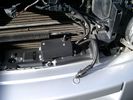
Battery Maintainer switch box and connector 723 viewsThe Hammond box contains a DPDT toggle switch with centre off. The Positive and Negative from each battery feeds to the switch. Depending on the setting of the toggle, (full left, full right,or centre off),the respective batteries connect into the pigtail that can stick out thru the grill when one wishes to connect the charger.
This allows one to charge each battery independently via a suitable battery maintainer. I use a CTEK unit that feeds a maximum of 3.3 amps at 14.4 or 14.7 VDC, depending upon setting. The wiring therefore allows for a slow recharge of either of the batteries separately if either one requires such.23 Mar 2010
|
|
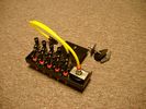
FASKIT rear showing gauge.922 views23 Mar 2010
|
|
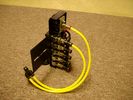
FASKIT on end view 864 viewsEnd and rear view of the FASKIT. Yellow lines are as shipped for hooking to the air supply; one line to valve/filler and other is to gauge. I will modify the arrangement to delete one of the yellow lines such that gauge line plugs into where the second yellow line is right now,(will be only one yellow tube), and then the air source line will plug into the port controlled by the valve, (hidden in this view but visible in other view). When white valve is in the ON position, gauge will read air source pressure, and be available to supply air to any of the selected four air springs. When valve is closed, the gauge will show individual air pressure in each of the air springs when a jumper is run between the gauge Schrader valve and the appropriate air spring Schrader valve. 23 Mar 2010
|
|

Air System Schematic with parts identified.1374 viewsAir system block diagram with components numbered and identified.23 Mar 2010
|
|
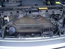
Plastic cover and Box back on in Front of Radiator 638 viewsThe wiring loom is below the cover - nothing is crushed or distorted and all fits back together OK. The black plastic box with the DPDT, (centre OFF), toggle switch is to tie the battery maintainer to each of the two batteries per the Traxide Dual battery install. I can also get power to the power door locks if all fails.23 Mar 2010
|
|
Wire (tubing) loom on right to down into bumper 465 viewsThis shows the 19mm loom in the trough between the bumper and the rad as it drops down into the right fog light area.23 Mar 2010
|
|
Wiring (tubing) loom at left headlight showing FASKIT panel 584 viewsThis shows the wiring (tubing) loom and FASKIT panel mounted to left wing. The loom moves a a couple of inches (50mm) towards the bottle once the headlight is put back in as there is not enough free space for the loom as located. The FASKIT panel is just visible at the top left corner of the picture. 23 Mar 2010
|
|
19mm wiring loom in trough behind bumper and in front of rad793 viewsThe 19mm wiring loom is large enough that a maximum of six 6mm air lines can be fished thru as required. The loom runs from the FASKIT panel located in the engine compartment behind the left front headlight, down and across in front of the rad and then down to the front axle valve block located behind and below the right fog light.23 Mar 2010
|
|
Wiring, (tubing), loom exiting temporarily from the front right fog light.569 viewsThe front axle air valve block is located just behind and below the fog light. Access to the valve block is by removing the right front fender liner, (or the bumper). The FASKIT lines are attached to the left and right front air spring lines at this location; also compressor air is taken from this location as well. Cutting the lines at as few different locations makes it easier to find leaks at a later date. As above, five 6mm air lines run from the FASKIT panel to the front axle air valve assembly and run within the loom. Two pair of the lines are for control of the air springs, and the fifth line taps the air supply at the valve block assembly off the compressor. This will be the air source line rather than tapping in directly to the high pressure air tank. 23 Mar 2010
|
|
19 mm wire, (tubing), loom rising from below at left headlight657 viewsFrom the FASKIT panel, five air lines fit in the 3/4" (19mm) wiring loom and feed to the front air valve block located behind and under the right front fog light.23 Mar 2010
|
|
View from front left side looking towards rear aux battery compartment under cover 647 viewsAs there is no Fuel Burning Heater in the NAS V8 petrol vehicles, there is space available to install the FASKIT panel here. The piping is such that each air spring can be isolated from the air system and then filled one at a time manually via the Schrader valve. There are five Schrader valves and five shutoff valves. The fifth valve nearest the gauge controls air from the compressor, and can provide fill up air via a jumper fill line assuming the compressor is still operational.18 Mar 2010
|
|
View of mounted panel from front left side878 viewsNote that all valve handles are shown in the OFF position, (the trouble position). In this case, the air that is in the air springs, (if any), is trapped in there - that is the valve blocks cannot vent whatever air is already in the air springs as the air lines between the springs and respective valve blocks are closed off by the FASKIT valves. In operation, there may be only trouble with one air spring, (perhaps a wheel height sensor), and as such, only one valve would need to be closed. If there was complete air compressor failure, then all valves would be closed and then as required, each spring could be manually filled from an outside clean dry oil free air source. 18 Mar 2010
|
|
View of mounted panel from front left corner737 viewsI drilled a hole for the supplied 6 mm tie down toggle bolt in a flat portion of the wing on which the panel sits. I inserted a 50 mm flat rubber washer between the wing metal surface and the underside of the black painted panel plate; also a 40 mm flat rubber washer between the supplied fender washer and the metal plate - just seemed like a good idea so surfaces mate well even if wing metal not completely flat. 18 Mar 2010
|
|
Power Window Circuit centered on Central Junction Box (behind glove box fuse panel)736 viewsRelay 143, the power window relay, and most other relays and FET's as well are built into the back of the passenger side behind the lower glove box fuse panel.
As such, the relays etc are not removable, jump-able, or serviceable.09 Mar 2010
|
|
Power Window Circuit Sheet 2 Central Junction Box to Passenger Front Switch365 views09 Mar 2010
|
|

Power Window Circuit Sheet 3 Central Junction Box to Rear Switches392 views09 Mar 2010
|
|

LLumar "windscreen" clear Infra Red reduction side window film930 viewsThis is a data sheet on the LLumar brand of what they call Windscreen Film; It is almost clear, (has a bit of a blue tint), and reduces both the Ultra Violet fading and sun burn rays which most all films do as that is easy, plus more significantly, the Infra Red heat rays. That is rare as it is not so easy or cheap to do.
AIR80BLSRHPR (blue) is what the IR rejection film is listed as in the brochure that I used. http://www.llumar.com/en/AutoWindscreen.aspx
I had it applied to the front side windows as well as the front sun roof. One can feel the difference when the sun is low and streaming thru the side glass or high and coming thru the sun roof. Rolling a side window down is the simplest test of effectiveness re the rejection of the heat energy.09 Mar 2010
|
|
FASKIT air panel unmounted843 viewsThis is the manual air valve panel that is mounted in the "empty" space where the FBH normally resides. The gauge reads to a maximum of 25 Bar. The air tank relief valve is set just over 16.5 Bar (240 psig); the front air springs run maybe 9 Bar, (130 psig) and the rear, somewhat less, perhaps between 5 and 8 Bar. (70 to 115 psig). Max theoretical air spring pressure at full compression due to a big bump and full gross is approximately 27 Bar (390 psig).09 Mar 2010
|
|

John Guest (LR part # STC8580) push in straight 6mm tubing to tubing connector730 viewsThis picture is similar to the air suspension pneumatic fitting union that Land Rover sells as replacement part # STC8580. This is a 6mm OD tubing size push in to install straight tubing to tubing fitting. The STC8580 comes with what are called "Collets" at each end that cover up the press to release feature underneath. See the John Guest web site www.johnguest.com under the Pneumatics section and also in Downloads for their catalog for install and remove instructions.
The actual fitting that Land Rover provides has an interior 4mm OD ferrule that slips inside the 4mm ID of the nominal 6mm tubing. Hence the fitting depicted and part number are not actually correct. I have not yet been able to obtain the John Guest part number for the LR fitting.
The fittings that show in this doc are what I call food service fittings rather than transportation or Air Brake fittings. The part LR sells, (STC8580), is the Air Brake type for transportation. 09 Mar 2010
|
|
Power Window Circuit Sheet 1 from Battery to Central Junction Box (fuse box behind glove box)353 views05 Mar 2010
|
|

Power Window Components475 views05 Mar 2010
|
|

Component Names related to Power Window Wiring Diagram283 views05 Mar 2010
|
|
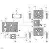
Block Diagram of Disco 3 / LR3 Air Suspension System.1552 views28 Feb 2010
|
|
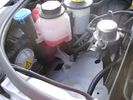
Empty space in NAS LR3 for location of FASKIT panel599 viewsThe empty space is available as the North America Spec gasoline engine LR3's do not have the Fuel Burning Heater installed. The air lines from the four air springs and the air tank will appear to rise up from under the headlight assembly. The lines to the front block valve assembly located behind the front right fog light will sort of run within the bumper across the front of the radiator down into behind the righthand fog light. The rear lines somewhat follow the path of the existing air feed line from the front valve assembly to compressor. Rather than be located between the left front fender liner and left metal wing however, the four lines will feed thru the empty wing space inside and above the wheel well arch and exit down by the left front mud flap. From there, the lines run along the left frame member above the air tank and then parallel the frame over top the compressor to the top of the rear left air spring where the rear air block valve assembly is located. 28 Feb 2010
|
|

Wheel cut thru definitions and specs898 viewsNote the location of REAR SPACING and also OFFSET; probably two of the most important dimensions and not always understood as related to wheel size and relationship to the brake components.
For the 3, Rear Spacing is approximately 6.5 inches or 165 mm for a nominal 8" rim. Offset is 53P or 53mm Positive, which means the distance from the machined hub flat mounting surface to the rim's true centreline is 53 mm in the outboard direction. (The rim illustrated has a negative offset.)
As Positive offset increases, this means the wheel wraps around the disc brake mechanism more deeply, and hence the more the wheel would cover the brake parts. This is why most 18" wheels will not fit with the larger Brembo "supercharged engine" brake calipers.
Pitch circle diameter is 120mm; Pattern is 5 lug, and the tyre load rating is 112 with a recommended tyre speed rating of H or higher along with the XL load rating. For the 3, the stock tyre diameter is about 30 inches. The 255/60/18 or 255/55/19 OEM tyre outside diameter is 30.04 inches; Wheel lug torque is from 130 to 150 Nm or 96 to 110 lbf-ft and the lug nut hex socket size is 22mm.
Max Load High Speed Driving Tyre pressures are Front, 33 psig, (230 Kpa) and Rear, 42 psig, (290 Kpa).
The OEM rims are rated at 940 kgs, the highest that LR makes, hence while rims from other Land Rover products may physically fit, the odds are they are under rated in a weight sense.28 Feb 2010
|
|

Sandcat / Ford F250 / Defender 2?725 views28 Feb 2010
|
|

Yes, that is Marilyn in better days.1594 viewsIf she had just been content to fool around with blokes who liked Land Rovers ...28 Feb 2010
|
|
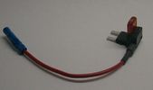
Littelfuse Mini Add-A-Circuit FMH200BP and OFH0200ZP1623 viewsFound this jpg somewhere on the forum - others are using them as it is a good way to tap the fuse box to add a fused circuit, or in this case, to modify a circuit to add a switch such that the fused circuit is switched. In my SmoothTalker gallery, there is a PDF from Littelfuse specifically related to this Add-A-Circuit device.
Before you install the Add A Circuit for any application, take an ohm meter and trace out the circuit path of the two pair of slots that fuses could insert into. The path is more complicated than one might first think. As such, the orientation of the fuse holder in the socket may matter depending upon the application. If the application is a circuit diverter, (as the F35 mode is), as opposed to a mere accessory adder, orientation matters. 23 Feb 2010
|
|

PDF of Mini Fuse data re LR3 / Disco 3 fuses.1854 viewsThis is just a data sheet regarding the MINI fuses that are common in the 3.23 Feb 2010
|
|
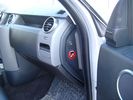
Air Suspension ECU Fuse 35P Shut Off Switch2635 viewsA more distant view of the shut off rocker switch in the ON position which is the normal position for when all is working as Land Rover intended.
Ideally, (but not totally necessary), the F35P circuit should be powered or de-energized after the various computers have gone to "sleep".
Similarly, removal of the F26E or F3E fuses is preferable after the computers have all gone to sleep but it appears that no real damage will be done if the fuses are removed while the system is energized. Pulling F26E is the main full time fuse that powers the air suspension computer. As such, once F26E is removed, pulling F3E is not really required.
Power for the compressor goes thru the 60 amp fusible link and relay, however control of the relay is via the air suspension computer so depowering the air suspension computer effectively depowers the air compressor and the internal exhaust valve relay/port. 23 Feb 2010
|
|
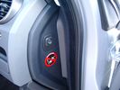
Air Suspension ECU Fuse 35P cut off switch.3821 viewsThis shows the SPST rocker switch mounted in the blank plate installed in lieu of a manual passenger side air bag shut down switch - now automatic via passenger seat pressure switch. Fuse 35P (5 amps) is located in the interior fuse box behind the lower glove box and protects the ignition power supply to the Air Suspension ECU. When the SPST switch is moved to the OFF position, the RAISE /LOWER switch on the centre console is not powered, and hence does not function. As such, some signals from the wheel height sensors and CPU are ignored. By itself however, removing F35P will probably not stop the 3 from self dropping, particularly after the engine is turned off.
Fuse F3E, (5 amps), located in the engine bay fuse box by the starting battery protects the circuit that provides feedback to the Air System ECU indicating that the Compressor Relay has successfully operated and that the Air Compressor is or should be operational, can also be removed, (but is probably not totally necessary), as it gets its power thru F26E. Hence Fuse F26E, (20 amp), also located in the engine compartment fuse box is the fuse that must be removed. This fuse protects the circuit that provides full time battery power to the Air System ECU. When in place, current thru the fuse powers the periodic re-levelling action, (usually lowering a bit with that brief air release noise), that often occurs when the vehicle is parked and the engine is off.
Removing F26E fuse will stop the auto levelling action and also inhibit any other down to the stops signals, (engine running or not). When F26E is removed, no power can flow thru to F3E, hence removing F3E is more for insurance than an absolute requirement. The same with F35P, removing F26E removes primary full time power from the Air Suspension ECU, and hence removing the F35P fuse should not really be required either as long as F26E has been removed.23 Feb 2010
|
|

Land Rover Aerial Fin images for both Glass and Metal Roof Disco3 / LR3864 viewsAs well as the two different fins, this pdf also shows the plastic blanking plate for glass roof vehicles where no fin is installed.
The glass roof fin is secured by two security screws from the top into a plastic frangible glue on gasket. The hope is that when struck, the fin will shear off and not crack the glass roof. Re the metal roof design, the fin is secured from underneath via two nuts.
The pdf also shows the various electrical bits related to the antennas. In the UK, the fin would house not only a cell phone antenna but the TV and satellite radio antenna electronics as well; in the States, the Sirius sat radio antenna and a G type cell phone antenna if the phone kit was installed would reside within the fin. The SAT NAV GPS antenna is located within the High Mount Brake Light plastic mounted to the upper rear hatch.21 Feb 2010
|
|

Interstate Battery Dimension sheet641 viewsThis sheet is hard to find - the sheet is not on the Interstate corporate web site but some dealer web sites display it. The pdf shows most of their available batteries including the H7 and H8 sizes that are the LR North America replacement batteries for the main starting battery. These batteries are of the Land Rover desired "shallow" cycle high discharge current Maintenance Free, (Ca Ca), internal construction, (not AGM, but instead, Wet Flooded Lead Acid with battery "caps" and Ca grid separators).
For the AUX battery , the H6, (BCI Group 48), is probably similar in dimensions to the Varta E12V75N that is popular in Australia. For that battery to fit in the second battery compartment, you must grind out the angled nibs on the inside front bottom of the LR black plastic surround, something I did wish to do and hence installed a Group 40R on a spacer. Alternately, one can choose an Interstate BCI Group 47 which is similar to a DIN H5 for the AUX location. I did this when I had to replace my 40R. No vertical spacer is required and the stock battery tie down bolts and clamp work well.16 Feb 2010
|
|

Varta Battery Dimension chart570 viewsThis pdf provides Varta dimensions for among others, the E12V75N, (old DIN H6 or 85605 or BCI Group 48 size). This appears to be a deep cycle battery and the choice for many re the Aux battery install as long as you are willing to grind away the angled nibs at the bottom front of the battery surround. My choice was a shallow cycle battery intended for cold weather related engine starting rather than winch use.
Note the pdf Varta batteries are all deep cycle batteries suitable for running fridges, winches etc, rather than for engine starting and hence a good Aux battery if those are the intended uses rather than engine starting.
Varta now makes a Varta G14 with AGM technology and known as a Stop Start Plus battery. It is 95Ah, CCA of 850A; length 353mm; Width 175mm; Height 790mm and is specific for these newer stop start vehicles such as some D4's. For the 3's, one is still probably better off with an H8 sized battery but of the older Wet Flooded Lead Acid type and battery caps rather than a sealed AGM.
The Land Rover part number for the recommended battery is LR033179.16 Feb 2010
|
|

Caterpillar Battery Size cross reference chart and battery profiles including post layout753 viewsThis pdf has a dimension, (metric and inches), cross reference chart plus another sheet that provides BCI and DIN cross reference numbers and shows post locations plus bottom ridge tie down locations, (or the lack of).
This data was for me, hard to find, and helps one in selecting a suitable physical size of Aux battery for the space available.16 Feb 2010
|
|

Deka Battery Dimension Data615 viewsThe battery size that I installed for my auxiliary was a BCI 40R battery as it was for me the easiest to fit and was also a cranking battery. The case profile was such that no tie down fins were located on either bottom end, (sides yes), and length wise, it was only about 11" (290 mm) long. As such, I did not have to grind the nibs at the front bottom of the plastic surround.
I did however raise the bottom of the battery above the angled nibs as I set the battery on a 1" (25mm) high plastic spacer. The total height, (battery plus spacer), was about 8" (200mm) so the battery top still fit under the Land Rover factory cover.
For the Aux battery, when I replaced the 40R, I installed an Interstate BCI 47 which is similar in size to a DIN H5. I was therefore able to eliminate the vertical spacer as the Group 47/H5 is the same height as the DIN H7/H8 stock LR spec starting battery. As such, the standard battery tie down bolts can be used without modification. The Group 47 battery is 9 11/16" long x 6 7/8" wide x 7 1/2" (190mm) high.16 Feb 2010
|
|
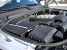
Overview of engine compartment from Main Battery side, (Passenger, LHD), looking across to Aux Battery753 viewsNote labels on main battery cover. The one you cannot read says that an auxiliary battery is installed on the other side. This is to warn service people should they wish to shut off all battery power.
The main starting battery is supposed to be of CaCa separator construction and DIN H8 or BCI Group 49 size. This means Calcium separators Wet Flooded Lead Acid, 13.9" long, 7.5" high and 6.9" wide.
On the Aux battery cover is a label saying to disconnect the blue Anderson single pole connector located under the cover by the brake reservoir. BCI Group 40R battery is small enough that the cover goes back on.15 Feb 2010
|
|
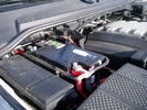
Main starting battery showing 1/2" hole drilled for power cable egress910 viewsView of OEM battery in Left Hand Drive LR3. This is supposed to be a Battery Group BCI 49 or H8 sized battery but in reality is the slightly shorter BCI 94R or H7 battery that fits easier lengthwise, (12 3/8" vs 14").
Note the 10mm hole drilled in plastic of surround to allow for entry of main power cable that runs between batteries. The cable bolts to a spare 6mm threaded hole in the OEM battery cable end; the light gauge wire runs to the front of vehicle to a connector for the CTEK MULTI US 3300 charger. Coloured felts, (red and green), are a material treated to reduce battery post corrosion. The OEM battery ground cable is only about a foot long and runs to an 8mm stud located on the inner fender just to the rear of the fuse case.15 Feb 2010
|
|
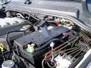
BCI Group 40R Deka 640RMF battery showing vent hose run forward to windshield washer reservoir area 1430 viewsRecessed post "Euro profile" battery to "match" OEM and stock Land Rover bracket; note that the Traxide SC80-LR module is mounted at an angle to allow for the main cable to sit under the cover so cover still closes.
The battery is a nominal 7", (180mm), high, but sits on a 1" battery spacer set under to raise the bottom front end of the battery such that the approx 11", (290 mm), length of the BCI 40R battery rises above the angled plastic nibs at the forward end bottom of the case front; hence sufficient space, (1/4", 5mm) remains at the brake reservoir end.
Also the 40R battery does not have hold down "flanges" on each end; on the sides yes, but not the ends so no additional length is required.
When I had to replace the 40R, this time I installed the shorter, (9.625"), taller, (7.5") Interstate BCI 47 / DIN H5 battery which eliminated the spacer on the bottom and better fit the stock LR tie down bolt lengths. Deka also has a BCI 47 / DIN H5 that would work fine as well.15 Feb 2010
|
|
375 ml jam container372 viewsThese are the 375ml Danish Orchard brand jam containers. They fit fairly tightly into the original old style, (2005/6) Land Rover 3 factory cup holders. The extra height provided by the containers can be an advantage. I have a similar assortment of containers in some of the door panel located wine bottle holders to better hold containers of lesser valued products. 11 Jan 2010
|
|
ScanGauge II on steering column of LR3800 viewsMAP is Manifold Absolute Pressure, what I call Vacuum.
The volts is I think the battery charging voltage as it moves around from about 12.4 when shut down to 13.5 when the batteries seems charged; 14.9 is about as high as I have seen it display.
You also have RPM, speed in MPH or KPH, coolant temperature and a bunch of other readings including sort of instantaneous fuel in a variety of units.
Also under some conditions, the ScanGauge will reset the MIL light as well. The background colour of the display can be changed to many different colours. I have it set to match the LR green.
11 Jan 2010
|
|

Patch Antenna mounted to underside of glass roof at rear.194 views29 Dec 2009
|
|
Blackberry Tour mounted on air vent showing default analogue clock 213 viewsA characteristic of the Blackberry is that when charging, the display can default to an analogue clock. Hence when the unit sits in the holder, the phone is being charged and the analogue clock displays. When the phone rings, the clock disappears and the call id displays.29 Dec 2009
|
|
BlackBerry Tour 9630 mounted on air vent265 viewsThe antenna amplifier is mounted lower near the steering column. The amplifier box is painted black but looks sort of gold coloured due to the lighting in the other jpg showing the amp located under/near the steering column.29 Dec 2009
|
|
|
|
|
|