| Last additions - NAV Radio BlueTooth phone and Rosen DVD |

Radio Head 6CD-465 Display diagnostics and low power procedure756 viewsThe one page doc outlines the procedure to access the diagnostics for the 6CD-465 entertainment system in most of our LR3's.24 Apr 2016
|
|
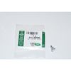
Clip Spring Metal FYC 500040 that holds LR together1747 viewsThe jpg is of the spring metal clip, Land Rover part number FYC 500040 that holds most of our 3 together - well at least most the interior trim parts.
If you are going to remove interior panels, you may as well stock up on a few for replacement as upon panel removal, the clips tend to spring away into deep never to be found voids within your 3.23 Apr 2016
|
|
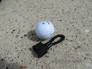
MOST fiber optic loop tool468 viewsThe looping tool in the jpg uses the Land Rover type plastic fiber optic cable with both ends feeding back into a female fiber optic connector that mates with the male fiber optic connectors on the Land Rover system.
The purpose of the loop is to allow one to disconnect MOST connected items such the BlueTooth module or the HK amplifier but allow the MOST system to still transmit signal from the head unit as the circuit would remain closed and hence complete. Of course with the Bluetooth module disconnected, there would be no Bluetooth available, however the radio and NAV would still function.
The looping tool allows one to troubleshoot the system by removing one component at at time from the MOST loop. In other words, what might appear to be a radio problem could be a Bluetooth problem - that sort of thing.16 Jul 2014
|
|
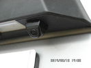
Tailgate Camera located above license plate.597 viewsThis aftermarket camera is mounted on my 2005 LR3 in almost the same location as the factory cameras. The factory units are mounted somewhat more forward closer to the metal of the tail gate and I could have done the same as well.
Note that the camera above is aimed a bit towards the centreline of the vehicle per the factory install. 26 Jun 2014
|
|
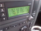
Voltage Display Page Radio Head Unit 118 14.2840 viewsThis shows the voltage/temperature/timer display page within the 6CD-465 radio head. There is a second file within this album, a doc file, that outlines the procedure to access the diagnostics.
The 14.1 volts number was the approximate vehicle system voltage with the engine running; the 118 number infers 11.8 volts which is the low power infotainment system shutdown cutoff voltage. The factory default setting is 135 or about 13.5 volts. By holding the keypad 1 button down, the 3 digit volts numbers will decrease 001 at a time until the keypad 1 button is released. Decreasing the number from 135 to some lower number should increase the time the system will remain on with the engine off.
The TEMP numbers refer to Fuel Burning Heater, (FBH), temperature values. 85 is apparently a high limit and 46 was the number when the jpg was taken. This number varies and given that there is no diesel fueled FBH in our NAS petrol engine vehicles, what the value refers to is unclear. The TIMER numbers also relate to the diesel fuel burning engine heater and perhaps make more sense being 00.21 Jun 2014
|
|

SDARS Satellite radio operating instructions 352 viewsThis is a 14 page pdf portion from the Owners Handbook with regard to operation of the satellite radio system operating on the Sirius channels.22 May 2014
|
|
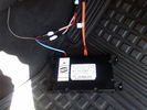
D4 Bluetooth AH42 10F845 AA module connected to 12VDC and MOST1210 viewsThis jpg shows the MOST bus connected to the AH42 10F845 AA module used in the D4 as well as +12VDC power from F58P connected. The power is split with a Y harness as the IHU (radio) for some reason required +12VDC power to the C2115-10 "mute" pin to keep the radio/CD audio from muting all the time.
With power on the pin, the radio audio does mute as it should when the cell phone rings and the hands free connects. The brown conductor feeds to C2115-10 and the blue to the module.
The module tucks up and hides behind the grey plastic section covering the forward portion of the passenger side tranny hump for left hand drive vehicles; for RHD, it would be located on the left side.
The pairing code is 2121 with this setup and not 1234 or 0000.14 May 2014
|
|

0000 LR Bluetooth dealer Kit install instructions1608 viewsThis 17 page pdf is mostly a series of pictures showing how to install the original Land Rover dealer installed Bluetooth kit for circa 2005 / 2006 three's. Also included are three wiring diagrams sheets related to the pairing code 0000 Bluetooth install.
This pdf is useful if you are now removing the 0000 kit to install the optical 2121 MOST D4 module, an easier install than the 0000 kit ever was. 26 Apr 2014
|
|

Rosen A10 Land Rover Installation Manual841 viewsThis is a 11 page pdf which is the Land Rover version of the A10 installation manual for our 3. It consists of a hundred plus sketches showing how and where to connect various cables, conductors and plugs.08 Feb 2014
|
|

Rosen A10 Manufacturer Installation Manual763 viewsThis is a 30 page pdf from Rosen that explains how to install the A10 unit. It is Generic in nature and hence carries detail not found in the LR specific install instructions. It also uses words and pictures instead of just pictures, hence can be a bit easier to figure out, particularily if you wish to take advantages of some of the hidden features not described in the LR material.
One of these features is how to hook up to a headrest display or I suppose even to the NAV in front.
08 Feb 2014
|
|

Rosen Owners Manual893 viewsThis 28 page Owners Manual is the Rosen version written specifically for the A10 model DVD Video Game Entertainment System player that may in attached to the roof of your 3.
Discussed is how to use the remote control, the wireless headphones, the TV feature if installed, and how to change from 16:9 widescreen format back to the older 4:3 format.08 Feb 2014
|
|
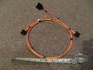
Fibre Optic MOST cable between components.559 viewsThis is a typical section of Plastic Optical Fiber (POF) optic cable with the orange coloured cladding covering the perimeter of the light transparent core. This is used as the MOST (Media Oriented Systems Transport) data transmission medium.
Note that each MOST 1355426 optical connector holds a pair of light conductor cables, one transmitting optical signal in, and the second, optical signal out. When connected to the other cables and devices, the cables form a continuous loop.
The light signal within the cable is red colour as one might expect. One break or disconnect anywhere along the loop shuts down signal transmission to all the connected components.05 Feb 2014
|
|

419-08 Low and High line radio systems components and operation838 viewsThis 15 page pdf displays the radio components including pinouts for both the low and high line head units and the two Harman Kardon amplifiers including the Logic 7 amp. The steering wheel controls for both the radio and phone system are also outlined along with mention of the Sirius satellite radio feature. 05 Feb 2014
|
|

415-02 Antenna systems for AM/FM, Satellite, GPS and TV systems542 viewsThis is a 5 page pdf related to the antenna systems for the AM/FM radio, Satellite radio, the GPS/NAV and the optional TV.05 Feb 2014
|
|

415-03 Audio System - Low and High Line Radios933 viewsThis 8 page pdf shows both the low and high line radios and their various components.05 Feb 2014
|
|

415-07 Video Information723 viewsThis is a 5 page pdf that explains the operation of the overhead DVD setup as well as the TV option.05 Feb 2014
|
|

Fibre Optic MOST bus plus CAN, LIN, GVIF and SLIN buses1539 viewsThis 7 page pdf introduces the fibre optic MOST bus, (the orange coloured cables), the two high and medium speed CAN buses, the Gigabyte Video InterFace, Local IntercoNnect, and Security Local IntercoNnect buses.04 Feb 2014
|
|

Entertainment System Wiring Diagrams2331 viewsThe 12 page pdf has the wiring diagrams for the low and high line "radio" and various components such as the amplifier, phone modules,NAV display, antennas and satellite radio and TV.04 Feb 2014
|
|

GPS NAV system components and operation999 viewsThis 16 page pdf describes the operation of the GPS navigation system and provides pin outs and equipment layouts. The GPS antenna amp and location is also shown. 04 Feb 2014
|
|

Older Cell Phone handset holder operation and components848 viewsThis 8 page pdf explains the operation of the older Cell phone handset holder and shows the various components as related to the radio and phone buttons etc. 04 Feb 2014
|
|
![Filename=LR3_Radio_Removal[1].pdf
Filesize=190KB
Dimensions=320x240
Date added=04.Feb 2014 LR3_Radio_Removal[1].pdf](images/thumb_pdf.jpg)
Radio Removal from Radio Stack571 viewsThis shows how to remove the radio from the stack. Basically you remove the H surround first and then at least loosen all the Torx 20 screws left and right sides from the top down starting at the narrow unit that the four way flasher/locking buttons are mounted on.
The units kind of interlock, hence some movement of each is required to remove the radio by itself. I find it best to take out the four way flasher/locking buttons assembly first as that allows access to the fibre optic cable connector into the back of the radio head without too much tugging.04 Feb 2014
|
|
|
|
|
|
|