LR3 miscellaneous |
 |
| TITLE |
+ |
- |
| FILE NAME |
+ |
- |
| DATE |
+ |
- |
| POSITION |
+ |
- |
|
|

Engine Accessory Drive Description and Operation882 viewsThis 2 page pdf shows both belts for the 4.4L petrol V8; the primary serpentine belt, (the long one), and the shorter secondary that drives only the radiator cooling fan.
The various accessory pulleys the two belts are each associated with are numbered and an included table describes each.
When replacing belts and pulleys, count the number of grooves on both your old items and your new replacement parts. It has been known for an pulley with the wrong number of grooves to come with a replacement part or the replacement belt has the incorrect number of grooves; hence make certain the groove count on the new parts are the same as the removed items.
|
|

Alternator and Regulator Wiring Diagrams, TDV6 and petrol V8 and V61989 viewsThis is a three page pdf that shows the alternator and regulator wiring for the petrol V6, petrol V8 and TDV6. The pdf can be either printed or by right clicking on the displayed pdf, rotated as required for viewing.
Of interest is that the regulator gets its instructions primarily from the Engine Control Module (ECM) and only secondarily from the vehicles electrical buss. The conductor from the battery thru the 5 amp fuse F20E is to provide initial power to excite the alternator at startup and then secondarily, to instruct it if the PWM signals were not available. Primary instructions to and from the ECM are thru the two other conductors via a digital like Pulse Width Modulated (PWM) signal.
If F20E, the 5 amp engine compartment fuse box fuse is blown, the red alternator light on the dash will be illuminated. This means that the alternator could be OK, but if the F20E fuse is blown, no electricity will be generated. Hence check the F20E fuse if you get a red ALT light or some indication of the alternator not working.
Regarding operation of the red ALT light on the dash, it is not the regulator within the alternator that tells the red light to illuminate, or not, but instead the ECM. This is the reason the red light does not function in the same manner as with older vehicles. With the 3, sometimes you have illumination and sometimes not depending upon what the ECM is thinking. What this means is that you can have an alternator that is failing but the red light does not illuminate as the ECM is compensating for reduced alternator output - maybe by draining the battery and or cutting back on vehicle electrical loads such as shutting off or cycling the radio amplifier or heated seats.
|
|

Wipers, Front and Rear, plus Washers description and operation.818 viewsThis 17 page pdf describes how the wipers, front and rear, plus the washers are intended to operate. Also described is how the rain sensor is designed to function along with a table of the wiper delay timing parameters.
|
|

Alternator female plug looking down into top373 viewsThis shows the plug connected to the alternator wiring harness looking down into the top of the plug.
The cavity marked 1 is the AS or BATT SENSE and the wire colour most likely has Brown/Green on it.
The cavity marked 2 is the RC or ALT CON and the wire colour most likely has Red/White on it.
The cavity marked 3 is the L1 or ALT MON and the wire colour likely has Green/White on it.
I say "most likely" as the wire colours are not always the same on all vehicles.
Also the terminal 1 conductor destination is more likely C0570-175 rather than per the jpg.
The #3 pin is located closest to the big B+ terminal.
|
|
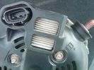
Alternator Plug and B+ terminal918 viewsPictured is the rear of the older Land Rover part # YLE500190 alternator showing the shiny cooling fin of the Regitar VRH2005-142 regulator under.
The first pin in the far left side of the connector is numbered #1 in the LR electrical wiring diagrams and is Battery Voltage Sensing (BVS); the middle pin, #2 receives a Pulse Width Modulated (PWM) signal from the Engine Control Module (ECM), and the right pin, #3 carries a PWM signal back to the ECM. Terminal Pin #2 on the LR wiring diagrams is called Alternator Control or ALT CON; Pin #3 per LR is called Alternator Monitoring or ALT MON.
Pin #1 is similar to what in older designs used to be called A or Batt, but is now called by Denso, S, AS, or Alternator Sensing for this design. Pin #1 also provides power to excite the alternator at startup until the PWM instructions over ride the battery voltage info. Land Rover calls the electronics under the pins a Smart Regulator, ironic, as it has to follow orders from the ECM rather than give the orders - new age thinking I guess. This is different from older design internal regulators that look at just the battery or the electrical buss voltage and then decides itself what to do.
It is almost like we are back to the external regulator designs of old, except that the ECM may decide that instead of telling the alternator to make more power, to load shed, and hence shut down the heated windscreen, seats, or whatever other electrical loads it decides are appropriate. My view is that the "smarts" are in the ECM and that the "regulator" should be regarded if not dumb, then as being a slave to the ECM.
|
|

Frame Jacking Points showing where holes are located.1088 viewsThe four points marked with the arrows show where the holes in the underside of the frame are located such than one could insert a trolley jack pin type lifting adapter, (or as designed), the official LR scissors jack.
|
|

A Pillar Black Plastic cover install pdf - new type.1038 viewsThis 3 page LR pdf explains how to install the newer A pillar plastic covers and avoid instant water leakage as a result of the new design.
|
|

Cooling system hoses - 4.4L petrol V81108 viewsThese are the cooling system hoses on the 4.4L petrol V8. The little odd shaped bleeder hose, (LR006158), shown in the top right hand corner can give problems. There is a plastic tee with a threaded air bleeder outlet located in the middle of the hose. The plastic tee can or will fail due to I guess heat distress.
A BIC pen can serve as a field fix, however for your parts kit, a nominal 3/8" ID hose size brass hose barb inline connector plus a couple of hose clamps is suggested. Better yet is a threaded hose barb brass coupling or a tee and bleeder valve to allow bleeding of the line. Land Rover now makes the plastic bleeder valve that breaks available as a separate part, # LR027661, where 0 is a zero. As such, one can now purchase that part only for addition to your field fix parts kit.
|
|
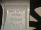
940 kg load marking on inside of spoke419 viewsThis is a typical 940 kg load marking on a Cromodora wheel rated for the 3. In this case, the wheel is the 6 spoke 19" wheel common to the HSE, LR Part # ALY72191U.
|
|
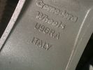
Cromodora brand marking on inside of spoke.326 viewsThis is the Cromodora brand marking on the inside of the 6 spoke 19" wheels, Land Rover part number ALY72191U. Similar brand markings are cast onto the inside surface of the spokes on all Land Rover Cromodora wheels.
|
|
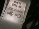
E-DOT and Japan wheel acceptance marking on ten spoke wheels.335 viewsThese are the E-DOT and Japanese wheel acceptance markings on the inside of one of the ten spokes of the 8J x 18" wheel, Land Rover part number ALY72190U or RRC500250xxx where xxx is the colour number, in this case, MNH for Sparkle Silver. There are similar markings on all Cromodora wheels for the 3.
|
|
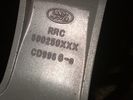
Part number moulded into spoke of 18" ten spoke. 322 viewsThis part number, RRC500250XXX is moulded into the backside of one of the spokes of the ten spoke 18" wheel. An alternate part number is ALY72190U or ALY72190U85 which relates to year and finish.
Another number is RRC500250MNH where MNH is also the finish, probably Sparkle Silver.
|
|

Defender in the Fog, another day on the job.459 viewsThis is another normal work day for a Defender - actually the jpg is from a Land Rover advertising shot, but it may just not be a set up one. I think it is an actual working Defender. Note the visible front tow hook and how the hi lift is just rope tied on; also the normal stock headlights and I guess dual spare tyres - just another day on the job.
|
|

Fuel Purge Valve and other hoses.846 viewsThis 6 page pdf shows the Fuel Purge Valve and associated hoses and describes how it is supposed to work. There are lots of good drawings of the fuel system. It is more complicated than one might think.
|
|

Series LR at Oil Sands Plant in Northern Canada circa 1968747 viewsThis is an end of shift picture taken about 1968 at the Great Canadian Oil Sands (GCOS) plant while under construction in the Ft McMurray area of Northern Canada.
I was surprised to see the yellow coloured Series single cab hardtop pickup parked in about the centre of the picture. I would say it is one of the few on site as most vehicles were Chevrolet's, (as are the other three trucks elsewhere in the view). The yellow painted vehicles including the Land Rover are most likely Bechtel owned - not leased - yes, that long ago now.
|
|

Key in Ignition Electrical Wiring Diagram1051 viewsThis shows the key in ignition wiring, (LGW, 1.5D), running from the key lock cylinder to the Central Junction Box, (CJB), thru 5 amp fuse F40P, located in the fuse box behind the lower glove box door.
You can remove the 5 amp fuse and the good news is that the ignition chime will not sound any longer; the bad news is that a bunch of other circuits that rely on knowing if the key is in or out no longer work.
Also note the Transponder Coil D219 reference.
|
|

LLumar "windscreen" clear Infra Red reduction side window film930 viewsThis is a data sheet on the LLumar brand of what they call Windscreen Film; It is almost clear, (has a bit of a blue tint), and reduces both the Ultra Violet fading and sun burn rays which most all films do as that is easy, plus more significantly, the Infra Red heat rays. That is rare as it is not so easy or cheap to do.
AIR80BLSRHPR (blue) is what the IR rejection film is listed as in the brochure that I used. http://www.llumar.com/en/AutoWindscreen.aspx
I had it applied to the front side windows as well as the front sun roof. One can feel the difference when the sun is low and streaming thru the side glass or high and coming thru the sun roof. Rolling a side window down is the simplest test of effectiveness re the rejection of the heat energy.
|
|
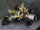
Rear Differential cutaway with E-Locker 1210 viewsThis jpg is from the link below.
There are another ten or so cutaways plus a whole file group showing a 2005 LR3 sectioned for the 2005 Chicago Auto show. Each jpg has an enlarge function to the bottom right of a main picture.
On one jpg you can see right into the stepper motor.
http://www.cutawaycreations.com/cutaways.php?project=land-rover-electronic-rear-differential#/IMAGES/car4/images/image1.jpg
Both the front and rear differentials are manufactured by Dana Spicer in the UK. Dana calls them a Clamshell design.
|
|

LR3 Electrochromatic Interior Rear View Mirror wiring diagram.852 viewsIt seems that there are two fuses, F69P and F5P that provide power for the interior rear view mirror. Ten amp F5P is a feed off the reverse gear relay and inhibits auto dimming when reverse is selected. Five amp F69P provides power to the auto dimming circuits and the garage door opener function if optioned.
The pdf can be downloaded and printed out. For on screen viewing, right click on the pdf and select the Rotate Clockwise button.
|
|
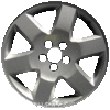
LR3 Sparkle Silver 6 spoke Wheel Cromodora of Italy 19 inch x 8 ALY72191U1108 viewsThese are the standard equipment 19" wheels on the 2005 LR3 HSE. The wheels are Made in Italy by the Cromodora company. Each are rated at 940 kg (2,072 pounds) and have an offset of 53 mm positive, (53P or +53).
I mention the 940 kg load rating as that is about the heaviest rating of any Land Rover product. The RRS and RRHSE both have lower ratings. What this means is that while a wheel from a Range Rover may physically fit, it probably does not have the brute strength of the factory spec Land Rover 3 wheel. There is no Land Rover product heavier than the 3, hence the 3 wheel design spec is the heaviest of the bunch.
|
|
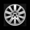
LR3 Sparkle Silver 10 spoke Wheel Cromodora of Italy 18 inch x 8 ALY72190U727 viewsThese wheels are factory standard on the 2005 LR3 SE and Made in Italy by the Cromodora company. Each wheel is rated at 940 kg (2,072 pounds) and has an offset of 53 mm positive, (53P or +53).
I mention the 940 kg load rating as that is about the heaviest rating of any Land Rover product. The RRS and RRHSE both have lower ratings. What this means is that while a wheel from a Range Rover may physically fit, it probably does not have the brute strength of the factory spec Land Rover 3 wheel. There is no Land Rover product heavier than the 3, hence the 3 wheel design spec is the heaviest of the bunch.
|
|

Wheel cut thru definitions and specs898 viewsNote the location of REAR SPACING and also OFFSET; probably two of the most important dimensions and not always understood as related to wheel size and relationship to the brake components.
For the 3, Rear Spacing is approximately 6.5 inches or 165 mm for a nominal 8" rim. Offset is 53P or 53mm Positive, which means the distance from the machined hub flat mounting surface to the rim's true centreline is 53 mm in the outboard direction. (The rim illustrated has a negative offset.)
As Positive offset increases, this means the wheel wraps around the disc brake mechanism more deeply, and hence the more the wheel would cover the brake parts. This is why most 18" wheels will not fit with the larger Brembo "supercharged engine" brake calipers.
Pitch circle diameter is 120mm; Pattern is 5 lug, and the tyre load rating is 112 with a recommended tyre speed rating of H or higher along with the XL load rating. For the 3, the stock tyre diameter is about 30 inches. The 255/60/18 or 255/55/19 OEM tyre outside diameter is 30.04 inches; Wheel lug torque is from 130 to 150 Nm or 96 to 110 lbf-ft and the lug nut hex socket size is 22mm.
Max Load High Speed Driving Tyre pressures are Front, 33 psig, (230 Kpa) and Rear, 42 psig, (290 Kpa).
The OEM rims are rated at 940 kgs, the highest that LR makes, hence while rims from other Land Rover products may physically fit, the odds are they are under rated in a weight sense.
|
|

LR3 AJV8 block heater location639 viewsThis 1 page pdf shows the screw in block heater location as related to the lower left side of the engine block.
|
|

LR3 Denso Alternator YLE500390 pulley view819 viewsNote the DENSO sticker on the side. Denso calls their nominal 150 amp 12 Volt alternator an SC2 design. SC means Segment Conductor which apparently increase the winding density of the stator coil, hence yielding a physically smaller lighter alternator for a given output. I presume the 2 means the second try at getting it right. A Denso part number is 4280003690 for the alternator, (there are others, as below).
Rotation is clockwise and the 54mm diameter pulley has 6 grooves (PV6x54). Count the pulley grooves on both the one you remove and your new one - some replacement alternators seem to ship with 5 or 7 grooves so you might be swapping pulleys.
A previous LR part number was YLE500190 for the older variation of the newer YLE500390 unit.
An additional part number for a factory rebuilt is Nippon Denso 210-0569 for the petrol V8 alternator. Other Nippon Denso numbers include 104210-3690 and 104210-3691. The Lester number is 11206 which relates to another Denso number of 290-5287. WAI uses 11206N.
From 2006 to 2009, the internal regulator is a Transpo IN6349 and of the B circuit type if it can be said that applies to PWM, (Pulse Width Modulated), regulators.
The "regulator" inside the alternator is therefore really not a regulator in the old sense of the term but instead an instruction receiver from the ECM that translates Pulse Width Modulated (PWM) signals into a form that the alternator understands – digital like signals from the Engine Control Module(ECM) into analogue like signals that the windings understand.
|
|

LR3 Denso Alternator YLE500390 rear view709 viewsThis picture shows the rear of the YLE500390, the Land Rover part number for a newer design alternator utilizing the Transpo IN6349 regulator with the "hidden" cooling fins. Note the visual difference in the rear view of the next file jpg.
If the alternator is a rebuilt, (service exchange unit), but Land Rover supplied, then the part number is LR008860 or similar. (Note that 0 in LR0 is zero.)
Two Denso part numbers exist for the alternator as well, 4280003690 and 4280003691. The rating of the petrol V8 alternator is nominal 12 VDC and 150 amps. In normal day to day operation, they seem to run about 14VDC - usually between 13.9 and 14.1 volts at the OBD port.
For the petrol V6, the LR service exchange number is LR008862, and the 2.7TDV6 is LR008861.
The bridge rectifier within the alternator is a 12 diode avalanche type, 117mm diameter, as used in Nippondenso 120 to 160 amp alternators with the Hair Pin stator. It is similar to a Transpo INR421 which is rated for 120 to 150 amp alternators. That is probably our primary problem - the rectifier is just too light. Alternate part numbers for the bridge rectifier are Cargo 237607, Mobiltron RM-29 and AS ARC6021.
Re the B+ stud, the INR421 calls it up as an M8 x 1.25 x 30 mm long course threaded stud; some say 34 mm but that may be longer than desirable.
|
|

Excel file for Rotors and Brake Pads part numbers for 4.4L V8 petrol LR3768 viewsComparing the cost of the various brands of brake parts is time consuming. Once you have your parts costs, this little spreadsheet will make collating the info easier.
I did not make any provision for labour costs, but the file can be downloaded and then modified. You can change Dollars to Euros or Pounds or whatever and insert lines for labour costs as desired.
Do not pay too much attention to the $ numbers as they are a mix of US and CDN, and from differing time frames, (prior to Spring 2011) . Also the brake part numbers are for my 2005 North America spec LR3 with the petrol 4.4L V8; diesel powered and supercharged 3's may have different part numbers
|
|

Power Door Lock Wiring694 viewsAbove is a 5 page, (pages 222 to 226), pdf wiring diagram for the power door locks for the LR3.
You can download and print as required. For on screen reading, use the right click rotate feature.
Additional pdf's regarding Locks can be found within the Gallery under the Power Windows and Door Lock Circuits heading.
|
|

Power and Heated Seats Electrical Schematic979 viewsThis 6 page pdf shows the wiring for the power adjustment of the front seats and seat heating for all the seats.
Re seat movement or the lack of, not only are there four related fuses, two 30 amp and two 5 amp, (one of each per seat), there are are two separate ground wires, perhaps of more significance than the power, if all movement on either side quits.
|
|

Fuel Tank Internals, Description and Operation 809 viewsThis 10 page pdf shows views of the fuel tank internals, what the various pieces do and describes how the fuel storage system is supposed to operate.
As usual, you can download it, save, and print as required.
|
|

Horn Wiring Circuit LR3578 viewsThe is the wiring diagram for the dual horn circuit.
The Horn Relay, (R133), is not a big black thing hidden somewhere but instead what is called a FET, (and it is hidden)!
This is a Field Effect Transistor that is built into the circuit board that is mounted to the back of the fuse box that is located behind the lower glove box door on the passenger side of the 3. The related 15 amp fuse, 12P, is mounted in this fuse box and is often called F12P, where F is for fuse, and P is for Passenger compartment.
This is to help differentiate from another fuse and relay box, (the usual kind), that is located beside the starting battery in the Engine compartment. FxxE is often used in the naming of those fuses.
|
|

Heated Windscreen Wiring Diagram408 viewsThis single page pdf is the heated windscreen wiring diagram. You can rotate the view by right clicking on the pdf and of course it can be printed out as well.
Relay R208 in the pdf is relay R9 in the Engine Compartment fuse box. Note both 30 amps fuses, F15E and F18E, also located in the Engine Compartment fuse box. If one side of your windscreen does not heat, the problem may be one of the two fuses.
|
|

Lug Nut part number RRD500290 outline sketch541 viewsThis single sheet pdf provides dimensions of the LR part number RRD500290 lug nut on vehicles from MY 2005 to 2008, (up to VIN 8A450459). From VIN 8A450460, the part number is RRD500590.
Visually, there is no apparent difference between the two part numbers. The dimensions appear identical as well. The shape, size, and profile of the Stainless Steel "hat" appears identical.
There are I presume differences in metallurgy to reduce corrosion and swelling of the hat or perhaps better sealing between the inside surface of the hat and the steel of the lug nut body. The reality is the differences are not immediately obvious however.
A 22 mm six point half inch or larger socket drive fits over the lug nuts. I use a nominal 36" long breaker bar with the 22mm socket - any shorter bar, best you be in shape. Depending upon your source, for both alloy and steel wheels, the lug nut torque value appears to be 103 lbf ft, (140 Nm); others suggest first tighten to 96 and then finish at 110 lbf ft, (130 and 150 Nm).
|
|

Yes, that is Marilyn in better days.1594 viewsIf she had just been content to fool around with blokes who liked Land Rovers ...
|
|
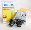
Philips D2S 85122 C1 Xenon 4300K projector HID bulb962 viewsThis is the 4300K OEM bulb in our HID Xenon projector headlights. People who design illumination systems regard the 4300K colour as a good compromise to provide what is called definition. This is effectively the ability to actually determine what an object being illuminated probably is. The more blue colour bulbs, say 5000K and greater, result in a reduction in the ability to distinguish detail, (regardless of brightness), of the object being illuminated. Effectively, you can see the object but you cannot quite figure out what it is. This is because the more blue frequencies means there are fewer other frequencies of light that allow our eyes to actually discern what an object really is.
The 4300K colour temperature applies to clear air conditions; for rain, dust, snow, fog, etc, then a yellow 2500K colour temperature is preferable. 2500K provides more contrast and there is less back splash of light off the air particles. In blowing snow, this means less sparkle back. Flat top cut off of the light beam, (which is the pattern our projector lights have), is important to reducing back splash - hence you do do not want roof mounted lighting for adverse conditions - as low down as possible is preferable, (which is why fog lights generally sit low.)
|
|
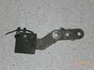
Radio Noise Suppression Capacitor NNW502820699 viewsThis is the radio noise suppression capacitor, part number LR020488 (previous NNW502820), that is mounted underneath and near the transmission. It is powered by fuse 10 amp F30E in the engine compartment. If F30E blows, (the fuse that also powers the transmission ECU), the problem is probably caused by the failed capacitor, not the ECU. A quick fix is just to disconnect the capacitor and replace the fuse as nothing bad seems to immediately result.
The above radio noise capacitor is not to be confused with LR004160, the ignition noise capacitor which is located under the black plastic engine cover on the right hand side above the air intake towards the rear of the engine.
The ignition capacitor is held on with a single 8mm bolt and a three wire electrical connector. Replacing the ignition capacitor as a routine maintenance prevention action at 100,000 miles, 160,000 km), has merit. It is a do it yourself kind of thing and easier to get at than the radio capacitor underneath.
|
|

Transpo pdf explaining the operation of Ford PWM regulators624 viewsThe 4 page pdf produced by WAI-Transpo explains the operation of the Pulse Width Modulated regulators located within the alternators on our 3's. Of note, the pdf states that certain of the Ford PWM regulators do not meet Ford spec.
The pdf explains the function of all the terminals and the apparent advantages of the PWM style over previous designs. Note that Ford calls their "engine computer" a PCM, (Power Control Module), whereas Land Rover, an ECM, (Engine Control Module).
|
|

Transpo Regulator IN6349 Pin Assignment715 viewsThis pdf shows the Land Rover and Ford pin naming for the 3 pins in the receptacle of the Transpo IN6349 regulator that accepts PWM signals. This jpg is as if you are looking into the receptacle located on the alternator.
Also provided are the Transpo pin names that are in common use and that some may be more familiar with plus some comments re testing.
The IN6349 regulator is used in the newer LR part # YLE500390 alternator. For the older YLE500190 alternator, the regulator is a Regitar VRH2005-142 unit that is shaped a bit different than the newer IN6349 regulator. Externally, the main difference is that no shiny fins are visible on the rear of the newer YLE500390 alternator. The pin naming and numbering is the same for both and both alternators are interchangeable.
|
|
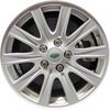
LR3 Silver 10 spoke grooved wheel Cromodora of Italy 18 inch x 8 ALY72201U85385 viewsThis is Land Rover part number RRC505360MNH or RRC505360XXX, a grooved ten spoke 18" wheel rated at 940 kg and found on circa 2006 RR Sports and some 2007 LR3's. An alternative part number is ALY72201U85.
This is an example of a wheel factory spec on the full frame older RRS that is also factory spec on the 3 or 4 and hence can be moved from the RRS to the 3 or 4. This is rare however. A factory spec wheel for a 3/4 can always go onto an older full frame RRS but not necessarily vice versa.
Just because a wheel is a 5 lug, 120mm bolt circle, +53 mm offset and made by Cromodora does not mean it has the required 940 km load rating. That also has to be confirmed by looking on the backside of one of the spokes for the moulded in load number in kg.
|
|

Sandcat / Ford F250 / Defender 2?724 views
|
|
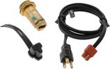
Block Heater and Cord for petrol V8 LR3 North America 120VAC529 viewsThe recommended 120VAC block heater cord is a Temro 3600003. This is a five foot long cord with what is called a Straight connector at the block heater end with holes for two pins; there is also a metal tab located between the two holes serving as the ground conductor. That cord, in addition to having the two pin holes plus ground tab end, is designed for both aluminum and brass heaters as that also matters.
The Land Rover part number for the Block Heater assembly is VUB504640 but is a Temro product not officially marketed by Temro as a Land Rover block heater. The Temro product number is 3100107 which shows as a brass body 30 mm threaded 700 watt 120VAC screw in block heater with a rectangular shaped depression and two pins suitable for the Temro 3600003 cord. Note the word BRASS as it mates with the aluminum OK.
|
|
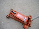
Trolley Jack Adapter823 viewsThis shows my 2.5 long ton, (2,540 kg, 5,600 pounds), trolley jack with the pin adapter that slots up into the round holes on the underside of the frame.
Use of the adapter when lifting by the left rear wheel ensures that I will not be jacking on the air compressor support; on the other three corners, it is much safer than merely jacking directly on the nearly flat narrow underside of the frame rail.
|
|

Front Runner Y style rear tyre carrier 582 viewsThis is the new Y or D shaped Front Runner, (out of South Africa), brand of rear bumper mount tyre carrier.
The big deal is the new self latching mechanism.
|
|

Vehicle Maintenance Log for LR3/4 D3/4 or other1135 viewsThis is a Excel file that you can download and then modify to suit. It is very simple, but allows me to keep track of most maintenance and fixes etc on my LR3. All columns and rows and boxes can be edited.
I did not erase any data in the various boxes so you could see how I am using it - again not very fancy but it works for me. Under the brakes column, one will see f6 r5 which is how I keep track of the condition of the brake pads. The dealer records the pad thickness at each oil change so that is where the numbers come from.
f is for Front Pads, 6 is for 6mm; r is for Rear pads, 5 is for 5 mm. New pads are about 10 mm; replacement is at 3 mm or less. The amber coloured brake wear dash warning light should come on at about 2 mm.
|
|
|
|
|