| Search results - "well" |
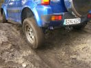
188 viewsJimny. Note how well the suspension works.
|
|
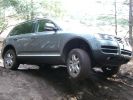
223 viewsThis is the Touareg with the 6cyl engine and rear difflock. did well, useless air-suspension though.
|
|
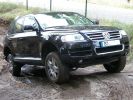
241 viewsThis Toureg is stuck - doesn´t look like it. After 8 hours of driving everyone agreed that with the big 10cyl. diesel engine you should probably oder the rear difflock as well... In this picture the rear left anf front right wheels have no grip, esp or whatever just doesn´t do it.
|
|
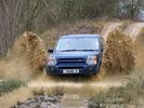
Yarwell Big Splash30 views
|
|
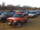
Group Meeting Yarwell90 views
|
|
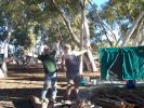
The roast is ging well, Pierre Springs206 views
|
|
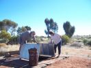
Well 12 , good water198 views
|
|
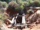
Abandoned Well217 views
|
|
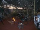
Well 26 campsite240 views
|
|
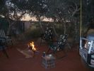
Well 26 campsite251 views
|
|

Well 51, the last well280 views
|
|
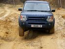
Yarwell28 views
|
|
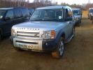
D3 @ Yarwell85 views
|
|
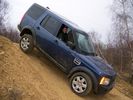
Yarwell26 views
|
|
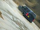
Yarwell lake24 views
|
|
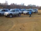
Yarwell 270 views
|
|
58 views
|
|
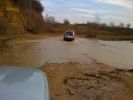
Yarwell Shallow Water 276 views
|
|
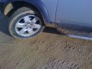
Yarwell 182 views
|
|
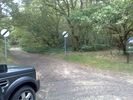
A De-restricted Bridleway,Well done Hampshire CC9 views
|
|
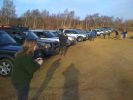
Ready for off at Yarwell74 views
|
|
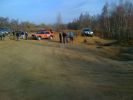
Training @ Yarwell70 views
|
|
Adam Happy @ Yarwell79 views
|
|
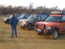
Yarwell 482 views
|
|
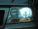
Standard hid bulb - light everywhere and glare caused by light in bottom of bowl97 viewsWhilst the beam pattern is ok the problm is that with 300% more light the spillage into the bottom of the reflector bowl is seen as glare by other motorists. it also is the reason the overhead motorway signs are lit up so well be bad retrofit xenons
|
|
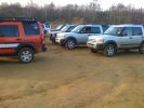
Yarwell 378 views
|
|
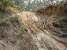
Northern entry to Palm Creek - near Bramwell Junction Cape York20 views
|
|

Boiling the Billy - Bramwell Junction Cape York25 views
|
|
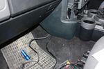
89 viewsCables out into passenger footwell
|
|
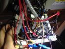
Roof Control panel26 viewsWell.. In reality it does not look as bad.. ;)
|
|

97 views72 hrs poste bite, not neck swelling
|
|

all mine44 viewsShe scrubs up well
|
|
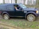
Well and truly stuck on a green lane at the weekend, there was a hill that does not show up in the photo!273 views
|
|
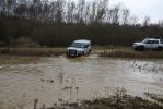
Yarwell February 0898 views
|
|
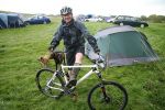
No, I didn\'t ride in wellies! ;-)67 views
|
|
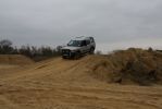
Yarwell February 08100 views
|
|
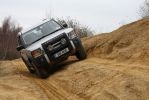
Yarwell February 08115 views
|
|
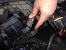
Thread upload48 viewsImage uploaded in thread 102519
|
|

Front Heater Doors Description and Operation1404 viewsThis 6 page pdf shows with coloured drawings the air flow thru the front heater as well as discusses the operation of the various air flow doors.
|
|

Air Conditioning and Heater Control Components2431 viewsThis is a 21 page pdf that really explains how the air system is supposed to work. Discussed are the exterior ambient air sensor, where and how it operates; the interior temperature sensor as well as humidity sensor.
|
|
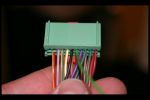
Heated Seat connections in front footwells 3190 views
|
|

plug footwell i think116 views
|
|
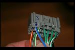
Heated Seat connections in front footwells 2183 views
|
|

plug to footwell111 views
|
|
Yarwell February 08109 views
|
|
Yarwell February 08112 views
|
|
Tigger - testing the new N44 bridge at Barnwell91 views
|
|
Silver Dico at Yarwell up the huge hill82 views
|
|
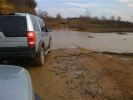
Yarwell Shallow Water76 views
|
|

88 views
|
|

Land Rover Aerial Fin images for both Glass and Metal Roof Disco3 / LR3864 viewsAs well as the two different fins, this pdf also shows the plastic blanking plate for glass roof vehicles where no fin is installed.
The glass roof fin is secured by two security screws from the top into a plastic frangible glue on gasket. The hope is that when struck, the fin will shear off and not crack the glass roof. Re the metal roof design, the fin is secured from underneath via two nuts.
The pdf also shows the various electrical bits related to the antennas. In the UK, the fin would house not only a cell phone antenna but the TV and satellite radio antenna electronics as well; in the States, the Sirius sat radio antenna and a G type cell phone antenna if the phone kit was installed would reside within the fin. The SAT NAV GPS antenna is located within the High Mount Brake Light plastic mounted to the upper rear hatch.
|
|
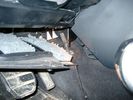
Air Conditioner Drain Hose on Drivers Side (LHD)2300 viewsThe corrugated rubber bit above and to the right of the gas pedal is the drain hose that goes down thru the carpet and floor sheet metal.
While it is bit hard to figure out from the jpg above, there is a rubber "strap" attached to the top of the corrugated hose that one uses to pull on to drag the hose up back around the black plastic heater "pan" drain. The same drain hose arrangement is on the other side as well.
One could I suppose run a plastic snap tie around the vertical pull strap if one was concerned about the hose slipping off again. See also the other jpg sketch which is from the Land Rover manual.
|
|

Altox WBUS-4 Installation in Discovery 3127 viewsstep by step with pictures how to install the Altox WBUS-4 in the Discovery 3 in footwell
|
|

how to install Altox WBUS-4 in engine room on Discovery 395 viewsthis is to show how to install the Altox WBUS-4 in engine room of a Discovery 3, but i would recommend to install it inside car in footwell, see other PDF in this album
|
|
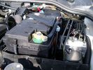
Aux Battery showing ground cable bolt "upside" down 1581 viewsIn order to obtain sufficient height clearance to get the plastic cover back on, I had to install the ground cable to the underside of the battery post connector.
Note the battery vent hose, (approx 5 ft required) is run down into where the windshield washer fluid container is located. There is not much electrical or metal in that area to be corroded by battery gas plus the open end of the vent hose tends to be protected from dirt and stays clean as well.
|
|
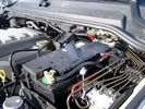
BCI Group 40R Deka 640RMF battery showing vent hose run forward to windshield washer reservoir area 1434 viewsRecessed post "Euro profile" battery to "match" OEM and stock Land Rover bracket; note that the Traxide SC80-LR module is mounted at an angle to allow for the main cable to sit under the cover so cover still closes.
The battery is a nominal 7", (180mm), high, but sits on a 1" battery spacer set under to raise the bottom front end of the battery such that the approx 11", (290 mm), length of the BCI 40R battery rises above the angled plastic nibs at the forward end bottom of the case front; hence sufficient space, (1/4", 5mm) remains at the brake reservoir end.
Also the 40R battery does not have hold down "flanges" on each end; on the sides yes, but not the ends so no additional length is required.
When I had to replace the 40R, this time I installed the shorter, (9.625"), taller, (7.5") Interstate BCI 47 / DIN H5 battery which eliminated the spacer on the bottom and better fit the stock LR tie down bolt lengths. Deka also has a BCI 47 / DIN H5 that would work fine as well.
|
|
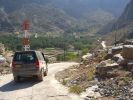
Bald Seet village164 viewsDescendign a steep concrete track over gravel into the villaeg of Ballad Seet. Curious in a dry, desert country to find verdent growth of palms, and agricultural produce on well watered terraces.
|
|
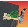
Battery Disconnect Wirthco 20308 Knob Top Post 893 viewsThis is a battery post style disconnect, usually for the negative terminal. There is a hole drilled in the round end off the battery so that flat terminal can be attached as well as the normal battery post terminal. I did not use this hookup arrangement, however I show it for information only.
|
|
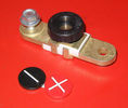
Battery Disconnect side post with + & - caps, top view621 viewsThis disconnect is designed for side post batteries. It can be used on either the + or - terminals. It can also be installed at the "other" end of the battery cable as well. In my install of the Aux battery, I installed this on the negative ground cable where the cable attaches to the body sheet metal. I have never used it but it seemed like a good idea at the time. The main battery hookup is pure stock.
For the hot side of the Aux battery, an Anderson PowerPole was used inline for the cable between the Aux and connecting to the spare bolt hole at the + post of the Main battery cable.
|
|
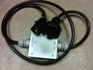
Box Closed with 7 Blade NAS connectors586 viewsBox closed up and ready for use. The box and cable connectors are reasonably weather tight and hence can be submerged for a bit while doing a creek crossing but as with the 3, do not use the creek bed as a parking stall. Similarly, the connector recessed into the bumper will probably remain somewhat dry as long as you keep moving but if you get stopped, well that is another story.
As such, I put a vial of desiccant in the metal box prior to closing it up to reduce corrosion due to moisture build up.
|
|

Brakes Description and Operation2234 viewsThis is a 17 page pdf that describes the operation of the various braking systems: the ABS, CBC, DSC, EBD, ETC, EBA, EDC, and HDC. Also discussed is the yaw rate and lateral acceleration sensor as well as the steering angle sensor.
|
|
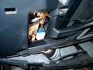
Brake Switch Visible thru Opening4982 viewsThe blue and white bit is the switch; the sort of gold appearing box,(it is really black), you will not see in your 3 as it is a Smooth Talker brand amplifier for my Blackberry phone antenna. This install is detailed in the SmoothTalker phone antenna section of my gallery.
One way to remove and install the switch is to lower the "horizontal" panel above the brake pedal as shown where the flashlight head is located. To actually remove the switch, you slide your hand thru the gap and rotate the switch clockwise 1/4 turn while watching thru the rectangular opening. Installation of the new switch is the reverse of above - 1/4 turn counterclockwise.
Before you remove the switch, note its orientation - horizontal with electrical wires to the left. That is the way it should look after replacement as well.
The second time I replaced the switch, I did it all thru the rectangular opening and did not remove the horizontal panel - that is experience helping out.
The knee kick you have to remove regardless. It is sort of hinged at the bottom so you just pull at the top and sort of rotate the knee panel and then pull upwards for two plastic "fingers" to clear the slots they reside in.
|
|

Me on the K5 launching over the "Mountain" at Cadwell65 views
|
|
25 views
|
|
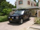
RHS view372 viewsSHows the Front Runner (SA) slimline windcheetah rack which is immensely strong. Takes my 110kg (oh gawd, I must get back on the diet and exercise regime) tramping over it when loading/unloading gear without a problem. Fittings are simply fixed or removed, and IMO very well designed and made. IPF 800 series driving and spots fitted to the front of the rack. IPF cam/reversing fitted each side and to rear of rack for negotiating rocky wadis at night. The G4 stickers were bought off E-bay as a set.
|
|
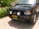
Front end327 viewsARB deluxe winch bar is very well made. Still allows Mantec sump guard to be used. Warn M8000 winch fitted - (wish I could\'ve found an M15000!) and IPF 900XS Extreme Series mounted with light stays to grille. Fog lights work fine with the replacement bumper, and indicators in bumpoer are effective too.
|
|
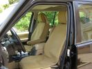
\'Escape\' canvas seat covers269 viewsFull set of these well made SA seat covers fitted to protect the Alpaca leather from constant exposure to Middle EAst sunlight and sand. They fit well, and to date have proved very durable. They include headrest and arm rest covers too.
|
|

Not a pretty picture93 viewsWell, there had to be one of the beaming owner in the album somewhere.
|
|
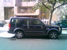
My Disco3 outside its other home, the City Inn Westminster307 views
|
|

My Disco3 outside its other home, the City Inn Westminster208 views
|
|
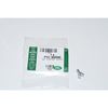
Clip Spring Metal FYC 500040 that holds LR together1750 viewsThe jpg is of the spring metal clip, Land Rover part number FYC 500040 that holds most of our 3 together - well at least most the interior trim parts.
If you are going to remove interior panels, you may as well stock up on a few for replacement as upon panel removal, the clips tend to spring away into deep never to be found voids within your 3.
|
|

Front Footwell Panel99 views
|
|

C pillar cover removed to facilitate removal of bin cover.9 viewsNote the "ribbon" behind the top left corner of the C pillar cover. This is something to do with the curtain air bags, hence do not mess with it. I dislodged the cover to make it easier to pull up and extract the black plastic bin moulding. It is not necessary to totally remove it and would be what I call a big deal - seat belt, air vent and ducting as well as that curtain concern.
|
|
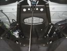
95 viewsSpare wheel well looking towards front of car.
|
|
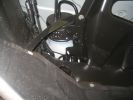
86 viewsCloseup of the cylinder/reservoir on front LHS of spare wheel well.
|
|
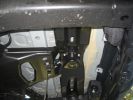
90 viewsSpare wheel crossmember
|
|
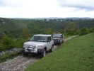
Top of Putwell Hill, one of the best view points in the Peak District264 views
|
|

Collection of EPB instructions & PDF\'s of Brake Posts662 viewsAll you need to change your brake pads or Brake Disks as well as adjuusting the Electronic Parking Brake. Includes the bedding in process for EPB pads
|
|

Part 1 of the LF Inset in Grill Installation224 viewsDetailes of the Grill preparation as well as the modifications needed to the front end.
|
|
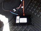
D4 Bluetooth AH42 10F845 AA module connected to 12VDC and MOST1213 viewsThis jpg shows the MOST bus connected to the AH42 10F845 AA module used in the D4 as well as +12VDC power from F58P connected. The power is split with a Y harness as the IHU (radio) for some reason required +12VDC power to the C2115-10 "mute" pin to keep the radio/CD audio from muting all the time.
With power on the pin, the radio audio does mute as it should when the cell phone rings and the hands free connects. The brown conductor feeds to C2115-10 and the blue to the module.
The module tucks up and hides behind the grey plastic section covering the forward portion of the passenger side tranny hump for left hand drive vehicles; for RHD, it would be located on the left side.
The pairing code is 2121 with this setup and not 1234 or 0000.
|
|
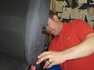
arm rest fit213 viewsthis is gary from trim-line... a job he knows to well as he is in landrover dealers most weeks..
|
|

415-07 Video Information726 viewsThis is a 5 page pdf that explains the operation of the overhead DVD setup as well as the TV option.
|
|

D3 reqar diff lock186 viewsView from right rear tyre well, left rear tire/rim visible on other side. Actuator motor visible
|
|
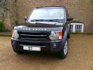
One D3, 2 days old98 viewsOur first trip out ..... Sunday Lunch (well you\'ve got to run it in gently, haven\'t you!).
|
|
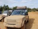
73 viewsAfter Yarwell
|
|
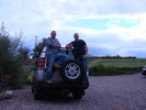
2011 in Fife26 viewsMy old D2 wiyh me on the left and my son Michael on the right. The day before he flew out to Afghan. Returned safe and well six months later.
|
|
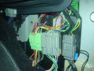
connectors - LHD - passenger footwell159 views
|
|
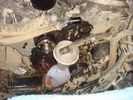
catching coolant - well nearly!70 views
|
|
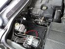
73 viewsAux battery tray - I found out you can remove the side as well as the top cover of the compartment.
|
|

Well trained!67 views
|
|
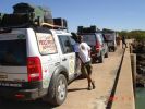
Crossing the bridge across the ruacana falls, just past the border post into Angola174 viewsWill - a chef of note, and a great companion. Kept us well fed, and well entertained
|
|

Paulo with a Kabeljou (I hope) caught at Foz du Cunene. His first beach fish! Well done Boet163 views
|
|
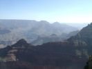
The Grand Canyon - well, part of it62 views
|
|

86 viewsLHS rear wheel well, with inner guard off. The rear AC lines (assuming you have an HSE) don\'t run in same way as the RHS, so on all cars, you can fold the red line inboard, with the bend roughly at the blue line, so that the very rare contact with larger tyres is eliminated.
|
|
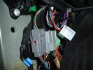
Aux connector in passenger footwell (disconnected)140 views
|
|

2nd Row footwell, showing water dispensing hose144 views
|
|

851 viewsD3 doing it's job rather well ! 17m from front to back! Belize green
|
|
274 views
|
|

Playing in the "Yarwell Rain"1092 viewsCALENDAR 2008 ENTRY - Taken at the Disco3.co.uk Training/Playday at Yarwell in November 2006. Picture taken by D3Matt, D3 driven by DiscoStu
|
|
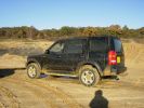
Yarwell 2006 Taken by D3Matt191 views
|
|
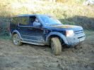
Yarwell 2006 by D3Matt209 views
|
|
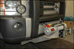
its even got wireless remote controll as well as traditional wired controller192 views
|
|
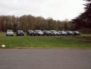
View from the Fairmile Carpark of 9 members cars198 viewsRange Rover Au Poivre had turned up by now - VA was having seat as well as steak sauce problems! I think we had 2 more turn up after this photo was taken
|
|
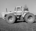
My favourite 4wd , spent thousands of hours farming with this. Sold it in immaculate condition.130 viewsVery well engineered Tractor. 16 Fwd grs,4 speed P/Shift weighed 1800 lb alone (if I remember correctly), 4 equall sized clutch packs, alternates 2 lay shafts with clutch packs, dry sump. no master clutch or TQ/C,Cat 3306DTA. 1 of 12 in Australia.
|
|

58 views
|
|

footwell - another angle171 views
|
|

Searching for the correct Aux socket in passenger footwell180 views
|
|
Footwell temp34 views
|
|
31 views
|
|
Glow_Plug_Tip_Swell16 views
|
|

Thread upload6 viewsImage uploaded in thread 144584
|
|

Eezi Awn53 views
|
|

43 views
|
|
Eezi Awn57 views
|
|

59 views
|
|
Eezi Awn58 views
|
|
Eezi Awn58 views
|
|

51 views
|
|
And then I spotted the lane up to the ex MoD site ... Well, you just have to don\'t you ..145 views
|
|

Well, would you swin in this. The pic doesn't show it, but this Loch looks a tad on the iffy side, and its drinking water ????157 views
|
|
Well, there wasn\'t a lock on the gate ???149 views
|
|

Yarwell February 08117 views
|
|
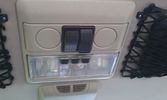
The on/off switches of the multimedia headrests17 viewsThese switches were installed to power on/off the previously installed gamecube and the screens attached to it.
When I removed the gamecube and lately the screens as well, I was clever enough (surprised as well) to leave the switches and all the wiring that I had running around.
They came in handy when I installed the multimedia headrests and are now adding an extra power on/off control of the screens.
|
|

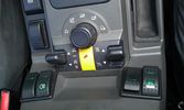
An extra 12V outlet17 viewsOn the passenger side, I added a 12V outlet which is fed through the fuse box in the rear and adds as such an outlet for whatever charger we don't want to have lingering around around the central console.
The USB charging outlets are visible as well :)
|
|
The on/off switch for the battery display22 viewsThe right inner switch 'powers' the auxiliary battery display. I might use that one to power on/off the driving camera (which will be arriving soon) as well. Although I'm not sure yet.
|
|

35 viewsThe facia had some bits sticking out which fit quite nicely with the supplied double DIN support. As I was going to use the DIN supports supplied with either the radio and the CB, I needed to remove those bits sticking out. They made the DIN support bend as well.
|
|

An extra twist on running lights30 viewsAdded those nice 120mm LED rings on the covers of the roofrack lights and have them connected to my roofrack lights switch, as I wanted to control the LED manually as well (I don't believe this is 'road-legal', hence why I opted for the manual solution).
|
|
middle well21 views
|
|
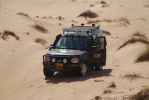
The start of a 2 day adventure109 viewsOverall, car performed really well in all desert conditions, but doesn't do so well on side slopes or full on straight and soft dune climbs. Find an easier approach with plenty of power on and she'll climb the sandy equivalent of Everest!
|
|
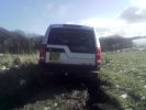
Well stuck out comes the superwinch!308 views
|
|
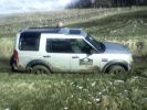
Well stuck out comes the superwinch!473 views
|
|
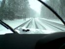
Snowy Kent571 viewsLow Res pic taken from Nokia Phone in Tunbridge Wells Kent
|
|
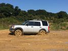
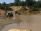
Yarwell 110 views
|
|
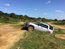
Yarwell 211 views
|
|
Yarwell 316 views
|
|

my boy Charlie56 viewsif all people i meet were as polite and well behaved as my boy the world would be a nicer place
|
|
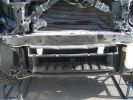
1609 viewsThese plastic bit\'s need to go as well
|
|
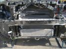
1651 viewsThe front bumper has to go as well
|
|

1828 viewsHere it is all back together with the winch looking well and truly hidden !
|
|
Wellies, wheels, walkies43 views
|
|
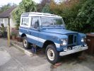
New door tops now fitted. Just needs new fuel tank, replacement footwells and a spot weld or two on the chassis!! 58 views
|
|
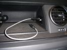
Connectors for Sound out and DC in181 viewsSound out (cable inserted) - connected to Aux connector in passenger footwell.DC in connector is always live
|
|
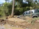
Last D3 through the deep crossing229 viewsThe water was stirred up by this time (didn't start off too clean due to heavy rains in the previous week) water was between 500 and 600mm deep depending on where the driver crossed. Away from the tree was slightly deeper but most drivers chose that line to be well clear of the tree.
|
|

D3 at Eastwell Manor Kent74 views
|
|
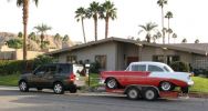
Towing my 56 Chevy264 viewsI towed my Classic Chevy about 650 miles from Palm Springs to Reno, including over the Sierra Nevada mountain pass (7,085 feet (2160 meters)) and the LR3 pulled very well.
|
|
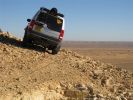
2009 Calendar Entry607 viewsView towards Jbel et-baga from, well, the edge of nowhere really!
Tunisia, Feb 2008
|
|

water in footwell 862 views
|
|

water in footwell 758 views
|
|

water in footwell 659 views
|
|

water in footwell 561 views
|
|

water in footwell 453 views
|
|

water in footwell 156 views
|
|

water in footwell 256 views
|
|

water in footwell 359 views
|
|
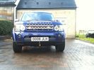
Full frontal154 viewsWell hidden. Uncle Ray sump plate, Goodwinch 9.5T winch and tray.
|
|

Footwell leak16 views
|
|

Footwell connector 1 back28 views
|
|

Footwell connector 1 front28 views
|
|

Footwell connector 2 back24 views
|
|

Footwell connector 2 front22 views
|
|
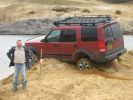
It\'s Wedged! (Yarwell Feb 2008)191 views
|
|

Yarwell Feb 2008158 views
|
|

Yarwell Feb 2008121 views
|
|
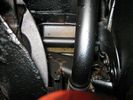
exhaust - well covered992 views
|
|

Dribbling into footwell here from closed door23 views
|
|
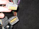
33 viewsConnector in LHS footwell, which connects (amongst other things) to the AUX input on the back of the stereo.
|
|
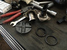
what you should be left with after the blanking procedure8 viewsApart from this, you'll also have to remove the pipes that connect the valves to the airbox. Not mandatory, but a proper job well done
|
|
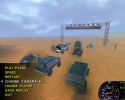
D3 in Insane186 viewsHmm - doesn\'t handle too well ... I was thoroughly pasted by the Baja Buggies and the Defender
|
|

install in footwell19 views
|
|

Interstate Battery Dimension sheet643 viewsThis sheet is hard to find - the sheet is not on the Interstate corporate web site but some dealer web sites display it. The pdf shows most of their available batteries including the H7 and H8 sizes that are the LR North America replacement batteries for the main starting battery. These batteries are of the Land Rover desired "shallow" cycle high discharge current Maintenance Free, (Ca Ca), internal construction, (not AGM, but instead, Wet Flooded Lead Acid with battery "caps" and Ca grid separators).
For the AUX battery , the H6, (BCI Group 48), is probably similar in dimensions to the Varta E12V75N that is popular in Australia. For that battery to fit in the second battery compartment, you must grind out the angled nibs on the inside front bottom of the LR black plastic surround, something I did wish to do and hence installed a Group 40R on a spacer. Alternately, one can choose an Interstate BCI Group 47 which is similar to a DIN H5 for the AUX location. I did this when I had to replace my 40R. No vertical spacer is required and the stock battery tie down bolts and clamp work well.
|
|
Yarwell February 08142 views
|
|
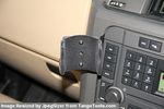
Brodit I phone 3 / 4 holder on ebay disc 4 metal bracket77 viewsWorks well
|
|
Yarwell February 08115 views
|
|

Euroncap crash test - footwell310 views
|
|
Yarwell February 08121 views
|
|

Littelfuse Add-A-Circuit MINI and ATO style data sheet151 viewsPDF from Littelfuse showing both the MINI and ATO style of fuse holders. The 3 uses the MINI size of fuse. The MINI Add-A-Circuit can be inserted in place of one of the existing fuse panel MINI fuses. The removed fuse is then inserted into the lower slot of the Add-A-Circuit and a second fuse in the second slot to protect the device that you are adding. The Add-A-Circuit is designed for a max of 10 amps on the second load, and I guess maybe the original circuit as well.
|
|

LLumar "windscreen" clear Infra Red reduction side window film937 viewsThis is a data sheet on the LLumar brand of what they call Windscreen Film; It is almost clear, (has a bit of a blue tint), and reduces both the Ultra Violet fading and sun burn rays which most all films do as that is easy, plus more significantly, the Infra Red heat rays. That is rare as it is not so easy or cheap to do.
AIR80BLSRHPR (blue) is what the IR rejection film is listed as in the brochure that I used. http://www.llumar.com/en/AutoWindscreen.aspx
I had it applied to the front side windows as well as the front sun roof. One can feel the difference when the sun is low and streaming thru the side glass or high and coming thru the sun roof. Rolling a side window down is the simplest test of effectiveness re the rejection of the heat energy.
|
|

LLumar AIR80 Air Blue 78 windscreen film IR reduction metal oxide341 viewsThis pdf summarizes the characteristics of the various types of window glass film available from LLumar. www.llumar.com
I had the Air 80 metal oxide sort of clear film, (windshield film they call it), installed on the front driver and passenger side windows to reduce the Infra Red penetration and hence heating effect on the front occupants. The film is barely visible from either inside or outside, however there is a noticeable reduction in heat penetration when sitting inside. In short, my arm does not get cooked.
Cell phone and GPS etc seem unaffected by the metal oxide film.
I also had the film installed on the three sun roof portions as well.
|
|
Thread upload0 viewsImage uploaded in thread 203557
|
|

Disco 3 Animated GIF for Series 60 Phones318 viewsThis animated GIF works well on Series 60 phones such as the Nokia 6600/6680 and Sony Ericsson K750i/W800. Image size is 192 x95 pixels
|
|

Battery Maintainer pigtail sticking out of Grill729 viewsThis is all you see when everything is put back together - just the pigtail and Weather Pack blanking plug. Most often, I have it all tucked back behind the grill.
In winter, there may be a second cord hanging out as well - the 120 VAC power cord for the engine block heater, a tea kettle like element inserted in the engine block. NAS petrol V8's do not have the Fuel Burning Heater, (FBH), installed, but instead in cold area markets have the block heater element assembly available as a dealer installed option. There is an argument to say that the heating element is factory installed in all cold climate V8 gasoline engines, however the appropriate power cord is not. If true, this means that all one needs to purchase is the area specific power cord and plugging in / attachment to the engine block located block heater.
As such, you will often see a conventional 120VAC three prong power plug hanging loose out of the grill of most vehicles here in the wintertime. In summer, most drivers tuck the plug back behind the grill as it is no beauty mark.
|
|
Boot lighting panel, finish side up 311 viewsThe above jpg shows the two 15 LED light assemblies as well as the SPST rocker switch mounted beside the W5W Land Rover supplied light.
The reality is that with the recent development of LED lighting that can replace a W5W T10 bulb, one can almost achieve the same results just by installing a LED bulb within the factory light.
|
|
View of mounted panel from front left corner740 viewsI drilled a hole for the supplied 6 mm tie down toggle bolt in a flat portion of the wing on which the panel sits. I inserted a 50 mm flat rubber washer between the wing metal surface and the underside of the black painted panel plate; also a 40 mm flat rubber washer between the supplied fender washer and the metal plate - just seemed like a good idea so surfaces mate well even if wing metal not completely flat.
|
|
Empty space in NAS LR3 for location of FASKIT panel602 viewsThe empty space is available as the North America Spec gasoline engine LR3's do not have the Fuel Burning Heater installed. The air lines from the four air springs and the air tank will appear to rise up from under the headlight assembly. The lines to the front block valve assembly located behind the front right fog light will sort of run within the bumper across the front of the radiator down into behind the righthand fog light. The rear lines somewhat follow the path of the existing air feed line from the front valve assembly to compressor. Rather than be located between the left front fender liner and left metal wing however, the four lines will feed thru the empty wing space inside and above the wheel well arch and exit down by the left front mud flap. From there, the lines run along the left frame member above the air tank and then parallel the frame over top the compressor to the top of the rear left air spring where the rear air block valve assembly is located.
|
|
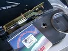
0.032" OD metal fishing leader and lead fishing weight clamped to existing wire rope 2122 viewsI used a size #0 lead fishing weight as a clamp to attach the 0.032" diameter flexible wire rope fishing leader to the release cable.
The pictured weight is the smaller #00 weight, however it did not work very well so reinstalled with the larger #0 size. I clamped to the cable as what breaks is the L retainer that is hidden in the actuator and holds the cable. When the L breaks, it lets go of the cable so you hear the clicking but there is no opening action.
Clamping on to the cable is an attempt to resolve that reality; also if the actuator electrically fails, the release mod should still do the task. Note in the picture the two Torx T15 screws that hold the gold plate to the plastic case and also the two 8mm cap screws that have to be loosened to remove the actuator from inside the door.
|
|
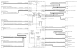
Power Window Circuit centered on Central Junction Box (behind glove box fuse panel)738 viewsRelay 143, the power window relay, and most other relays and FET's as well are built into the back of the passenger side behind the lower glove box fuse panel.
As such, the relays etc are not removable, jump-able, or serviceable.
|
|

Underhood Fuse and Relay Box drawing 3057 viewsShows the various fuse and relay locations. Fuse 3E, (5 amp), and Fuse 26E, (20 amp), as well as upgraded 70 amp Relay 7, part number YWB500220, locations are displayed. Relay 7 sends battery power to the compressor from the 60 amp fusible link called up as 10E. Fuse 26E is what provides full time always on battery power to the air suspension ECU and hence powers the auto level wakeup when the vehicle is shut down and say parked for the night. Removing F26E is the primary method to disable the air suspension system; Removing F35P is more if you want to experiment with it from inside.
I found it useful when I had a suspension problem, (actually a wheel alignment problem picked up by the steering wheel angle sensor), that only showed itself on the highway but allowed for no trouble light driving in the city. This was because in the city, the steering wheel was always in motion and rarely was the vehicle driven in a near straight line for very much distance.
|
|
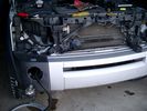
Wiring, (tubing), loom exiting temporarily from the front right fog light.570 viewsThe front axle air valve block is located just behind and below the fog light. Access to the valve block is by removing the right front fender liner, (or the bumper). The FASKIT lines are attached to the left and right front air spring lines at this location; also compressor air is taken from this location as well. Cutting the lines at as few different locations makes it easier to find leaks at a later date. As above, five 6mm air lines run from the FASKIT panel to the front axle air valve assembly and run within the loom. Two pair of the lines are for control of the air springs, and the fifth line taps the air supply at the valve block assembly off the compressor. This will be the air source line rather than tapping in directly to the high pressure air tank.
|
|

we put the fuses in the rear panel as well as the air tank gauge, air switch, and battery switch.417 views
|
|
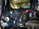
a few items being built in behind cover panel.443 viewsred inverter will have fluch mount plugs, air outloet will be flush, guage with window in lower pop-panel and switches and fuses for all rear items behind popout panel.
12v sockets being added as well, high and low.
|
|

Air Suspension Wiring Sheets3038 viewsThese two sheets show the wiring and fuses related to the operation of the air suspension system. Fuses F3E, F26E, and F35P are shown as well as the interior up down switch and the wheel height sensors.
As with all pdf's, you can rotate them to view plus download and or print out as you wish.
|
|

LR3 Denso Alternator YLE500390 rear view711 viewsThis picture shows the rear of the YLE500390, the Land Rover part number for a newer design alternator utilizing the Transpo IN6349 regulator with the "hidden" cooling fins. Note the visual difference in the rear view of the next file jpg.
If the alternator is a rebuilt, (service exchange unit), but Land Rover supplied, then the part number is LR008860 or similar. (Note that 0 in LR0 is zero.)
Two Denso part numbers exist for the alternator as well, 4280003690 and 4280003691. The rating of the petrol V8 alternator is nominal 12 VDC and 150 amps. In normal day to day operation, they seem to run about 14VDC - usually between 13.9 and 14.1 volts at the OBD port.
For the petrol V6, the LR service exchange number is LR008862, and the 2.7TDV6 is LR008861.
The bridge rectifier within the alternator is a 12 diode avalanche type, 117mm diameter, as used in Nippondenso 120 to 160 amp alternators with the Hair Pin stator. It is similar to a Transpo INR421 which is rated for 120 to 150 amp alternators. That is probably our primary problem - the rectifier is just too light. Alternate part numbers for the bridge rectifier are Cargo 237607, Mobiltron RM-29 and AS ARC6021.
Re the B+ stud, the INR421 calls it up as an M8 x 1.25 x 30 mm long course threaded stud; some say 34 mm but that may be longer than desirable.
|
|
![Filename=LR3_BMW_Ford_ZF_6HP26X-28X_Catalog_with_metal_pans_[1].pdf
Filesize=1194KB
Dimensions=320x240
Date added=26.May 2011 LR3_BMW_Ford_ZF_6HP26X-28X_Catalog_with_metal_pans_[1].pdf](images/thumb_pdf.jpg)
ZF 6HP26X and 6HP28X transmission parts showing various pans2818 viewsThis 42 page pdf is probably the most informative of all the material in this album. It is called a spare parts catalog but is much more than that. The material is specifically for the X variety of ZF six speed transmissions that are in the Land Rover 4WD / AWD models as well as BMW and Ford AWD vehicles.
|
|

Power Door Lock wiring diagrams530 viewsI thought I would include this 5 page power door lock wiring diagram pdf here as well.
When the pdf loads, if the views are vertical, it may be that you can right click on your mouse and a box will come up that will allow you to rotate the views clockwise so that the sheets are horizontal. Alternatively you can download the file and print each sheet yourself.
|
|

Heated Windscreen Wiring Diagram410 viewsThis single page pdf is the heated windscreen wiring diagram. You can rotate the view by right clicking on the pdf and of course it can be printed out as well.
Relay R208 in the pdf is relay R9 in the Engine Compartment fuse box. Note both 30 amps fuses, F15E and F18E, also located in the Engine Compartment fuse box. If one side of your windscreen does not heat, the problem may be one of the two fuses.
|
|
Thread upload1 viewsImage uploaded in thread 5
|
|

LTB00218 - Technical Bulletin - Water Leak into Footwell From Roof Opening Panel Drain Tube97 views
|
|

Lug Nut part number RRD500290 outline sketch544 viewsThis single sheet pdf provides dimensions of the LR part number RRD500290 lug nut on vehicles from MY 2005 to 2008, (up to VIN 8A450459). From VIN 8A450460, the part number is RRD500590.
Visually, there is no apparent difference between the two part numbers. The dimensions appear identical as well. The shape, size, and profile of the Stainless Steel "hat" appears identical.
There are I presume differences in metallurgy to reduce corrosion and swelling of the hat or perhaps better sealing between the inside surface of the hat and the steel of the lug nut body. The reality is the differences are not immediately obvious however.
A 22 mm six point half inch or larger socket drive fits over the lug nuts. I use a nominal 36" long breaker bar with the 22mm socket - any shorter bar, best you be in shape. Depending upon your source, for both alloy and steel wheels, the lug nut torque value appears to be 103 lbf ft, (140 Nm); others suggest first tighten to 96 and then finish at 110 lbf ft, (130 and 150 Nm).
|
|

Thread upload5 viewsImage uploaded in thread 198490
|
|
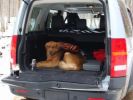
"Lady" taking a well deserved break.162 views
|
|

Mom\'s pet moose, well, she saw it on the road anyway.185 views
|
|
Wilko driving, Richard Aston navigating, Yarwell33 views
|
|
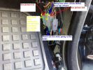
Heated Seat connections in front footwells 1277 views
|
|

footwell location of plugs150 views
|
|
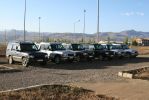
Some of the dozens of Disc 2s here at work - They have been well used and have taken a real hammering by the guys - Megga sub zero temps and tortuous terrain - One even spent several months buried in snow prior to recover in the spring.148 views
|
|

Yarwell February 08126 views
|
|
Thread upload11 viewsImage uploaded in new thread
|
|

55 views
|
|
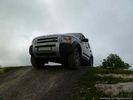
Eastwell Park May 2011220 views
|
|
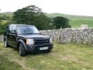
Day 1 of D3 ownership and Day 1 of going offroad!....well up a grassy hill anyway!41 views
|
|
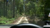
Access road to Pyrocarpa Flora Reserve120 viewsGenerally well formed road - a mixture of decomposed granite and sand in places. Evidence that it is used heavily used by trail bikes but we did not observe any that day.
|
|
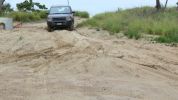
Fingal Road - Northern end187 viewsOnly sand driving we did was on this well packed and still damp sand leading to the sand pumping station (used for erosion control). Didn't even need to select Sand mode from the terrain tamer although I did put it in Extended Mode just in case.
|
|
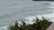
Point Danger - Looking towards Duranbah and NSW144 viewsNot a great swell but definately the most board riders I have seen there for a while. A dangerous beach, but great for board riders, adjacent to the Tweed River entrance.
|
|

Front right paw swelling66 views
|
|

Front right paw swelling near joint57 views
|
|
Front right leg swelling56 views
|
|

Swelling half way up right leg above joint73 views
|
|

Connector from passenger footwell64 views
|
|

146 viewsmy best self indulgance after my D3
and shes a special limited edition aswell so never ever going to sell it
|
|

handbrake works well31 views
|
|

Well, it doesn\'t look that bad, does it?57 views
|
|

Well, it looks a bit gloopy59 views
|
|
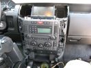
234 viewsConsole Trim Removed, as well as the top of the floor console.
|
|
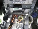
255 viewsThe console mostly re-assembled. You can see the dremel notch I made for the control cables, as well as the slack in the power and audio cables.
|
|
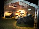
Well Lit Stand228 views
|
|

Yellow and Red Welly Crocs81 views
|
|

Regency Stages 2012128 viewsWorking hard, well almost! Radio duty for the Regency Rally at the Bath & West Showground (Shepton Mallet).
|
|
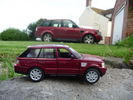
well a toy one8 views
|
|
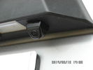
Tailgate Camera located above license plate.599 viewsThis aftermarket camera is mounted on my 2005 LR3 in almost the same location as the factory cameras. The factory units are mounted somewhat more forward closer to the metal of the tail gate and I could have done the same as well.
Note that the camera above is aimed a bit towards the centreline of the vehicle per the factory install.
|
|

255 views
|
|
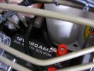
12v Isolator876 viewsEnsures that aux ery won\'t charge until the main batt is topped up and won\'t drain the main batt. I used the biggest I could find to take the load with no stress - especially the higher voltage on the landy. Came as a compete kit and works well.
|
|
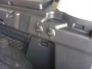
2 new rear 12v outlets933 viewsI added these two after market 12v oulets that are directly wired via a 30amp fuse to the aux battery. Why 2? Well you can never have enuff in my experieince... There\'s also a 12v socket wired to the ignition on the other side.
|
|
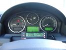
ScanGauge II on steering column of LR3801 viewsMAP is Manifold Absolute Pressure, what I call Vacuum.
The volts is I think the battery charging voltage as it moves around from about 12.4 when shut down to 13.5 when the batteries seems charged; 14.9 is about as high as I have seen it display.
You also have RPM, speed in MPH or KPH, coolant temperature and a bunch of other readings including sort of instantaneous fuel in a variety of units.
Also under some conditions, the ScanGauge will reset the MIL light as well. The background colour of the display can be changed to many different colours. I have it set to match the LR green.
|
|
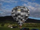
My Edit - Hot air balloon taking off from Bakewell on the 19-09-1054 views
|
|
23 views
|
|

Thread upload4 viewsImage uploaded in new thread
|
|

Thread upload4 viewsImage uploaded in new thread
|
|
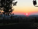
Sunset's Tenbury Wells16 viewsSunset's from home near Tenbury Wells
|
|

Sunset 2 Tenbury Wells19 viewsSunset 1st September 2013
|
|

376 views
|
|
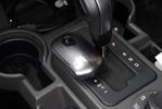
Small Kensinton trackball used to move the mousepointer while driving116 viewsUnfortunately the touchscreen does not work while connected to the PDA. A small bluetooth trackball solves this. All functions of the pda can be used doing this. Windows mobile has an onscreen keyboard which can be operated with the trackball as well.
|
|
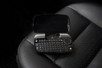
A keyboard can be used100 viewsThis little bluetooth keyboard can be used to enter text into the pda. It also has a tiny touchpad so the mousepointer can be used as well
|
|

10 views
|
|
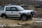
Yarwell February 08143 views
|
|

Thread upload3 viewsImage uploaded in thread 183936
|
|

Thread upload1 viewsImage uploaded in thread 183936
|
|

Thread upload1 viewsImage uploaded in thread 183936
|
|
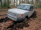
80 views
|
|
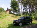
In the company of Wellington223 viewsIt was such a nice day, I couldn't help myself - just had to take a pic.
|
|
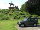
Wellington sorts out a helicopter197 viewsAnother pic by the Wellington Memorial.
|
|

Thread upload10 viewsImage uploaded in thread 158244
|
|
151 views
|
|
50 views
|
|
114 views
|
|
129 views
|
|
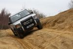
Yarwell February 08131 views
|
|
58 views
|
|
44 views
|
|

ZF 6HP26X-28X Plastic and Metal Pan part numbers and list585 viewsThis 3 page pdf lists the ZF part numbers for the factory metal and plastic pans. Note that the plastic pan is listed as the General pan, and the two metal pans as the BMW and Ford pans. The differences are subtle - drain related it appears.
Torx cap screw descriptions are provided as well as data on the differing gaskets and oil filters.
|
|

ZF 6HP26 Metal Pans, (top and bottom views), and separate Filter top and bottom views.1770 viewsThis single sheet pdf two views of the ZF metal pan for the 6HP26 transmission. The inside view shows the two magnets; the other is the bottom view. Also visible are the transmission bottom oil fill and oil drain holes that are sometimes utilized where access to the side fill is not possible. The ZF part number for the metal pan kit for our 6HP26X six speed is 1068_103_820_01 This includes the 21 shorter Torx screws, the metal pan gasket, and the separate oil filter as well as round filter seal. The ZF six speed LifeGuard6 transmission oil is extra.
|
|

ZF 6HP26 and 6HP28 Comparison plus oil pan and filter replacement options965 viewsThis is a 66 page ZF produced pdf that provides comparisons between the various ZF transmissions; also instructions regarding maintenance of the Mechatronic unit, the round seal; the various metal and plastic pans available as well as tips regarding changing the oil.
This ZF pdf has a number of colour pictures and part numbers within as well.
|
|
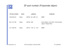
ZF Plastic Pan / Filter part numbers853 viewsZF, not Land Rover, part numbers for the various types of plastic pan depending upon vehicle manufacturer. The BMW pan is apparently different from the Land Rover pan even though the transmissions are 6HP26 units. No wonder each manufacturer has his own oil - maybe it is different as well. What I find interesting is the mention of Ford Australia and Ford USA separately rather than just Ford.
|
|

Mechatronic Replacement Hints plus drains for steel and plastic pans1113 viewsThis 22 page pdf shows colour views of the Mechatronic unit as well as good illustrations of the drain and fill ports in both the plastic, page 17, and steel pans, page 18.
Page 8 details the replacement of the sealing sleeve where the electric wire feed thru the case into the Mechatronic unit. The seal is normally replaced when a new pan is installed as the seal is a known leakage point.
|
|
|
|
|