| Search results - "this" |

0000 LR Bluetooth dealer Kit install instructions1608 viewsThis 17 page pdf is mostly a series of pictures showing how to install the original Land Rover dealer installed Bluetooth kit for circa 2005 / 2006 three's. Also included are three wiring diagrams sheets related to the pairing code 0000 Bluetooth install.
This pdf is useful if you are now removing the 0000 kit to install the optical 2121 MOST D4 module, an easier install than the 0000 kit ever was.
|
|
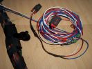
heated seat (base) wiring411 viewsThe Small connector takes the plug from the seat back pad, the larger connector (with red) is fitted into the multiplug casing uder the seat - the male side of this is already pre-wired.
|
|

Scorched Pad14 viewsThis is where the seat rod made contact with heating element.
|
|
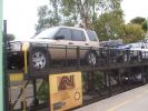
01 Start of Xmas 07 trip across the Australian Nullabor243 viewsThis is the preferred method of travelling 2500km of Nullabor desert when time is short (the Indian Pacific train). Next stop is Adelaide.
|
|
168 viewsthis is Albert 15 years old, showing the virtues of travelling club class, in the rear of a disco 3
|
|
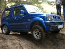
200 viewsSuzuki Jimny. Some holes were deep enough to swallow the little fella, but it got out as long as all wheels were on the ground. No difflocks or electronics in this one.
|
|

Got Married!241 viewsOccasionally the car does get a clean/polish, this was a special occasion :-)
|
|
02 On banks of Darling River, Back of Bourke158 views"Back of Bourke" is the typical definition of the start of the Australian Outback. This was after crossing the Darling River "back of Bourke" on 8 Jan 08. We were the first vehicle to start driving after floods had closed (first time in 8 yrs there was any water in the river).
|
|
02 Last Photo before the little wheel problem saga222 viewsThis is my D3 with trailer on the banks of the Darling River, literally "back of Bourke" (the regional definition of the start of the Australian Outback). We were the first vehicle in a week to try and drive this route from Bourke to Wilcannia on the account of floods (first water in 7 years). Little did we know that 3 hours later there\'d be a bit of a wheel and tyre problem appearing...
|
|

the D3, 17" with stock tyres, working very good in the mud ! Still estonished by this ...617 views
|
|

This is why the bus was canceled!39 views
|
|
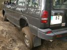
209 viewsDiscovery 1. Is stuck in this picture. No difflock.
|
|
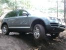
223 viewsThis is the Touareg with the 6cyl engine and rear difflock. did well, useless air-suspension though.
|
|
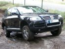
241 viewsThis Toureg is stuck - doesn´t look like it. After 8 hours of driving everyone agreed that with the big 10cyl. diesel engine you should probably oder the rear difflock as well... In this picture the rear left anf front right wheels have no grip, esp or whatever just doesn´t do it.
|
|
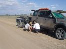
03 The first bit of tyre/wheel problem251 viewsSomewhere in the Australian outback on a 45 deg C day in Jan 08, a D3 had a bit of a flat tyre problem. "No worries, mate" st we had 3 spares (plus 2 more if we abandon the trailer), 150l of water, 4 days of food, and an EPIRB if things really go crook. The first clue that this was not a "normal" flat was when I handled a wheel nut and ended up with a blister from a burning hot nut (the ambient wasn\'t THAT hot).
|
|
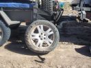
04 Damaged Tyre301 viewsYes, there\'s no doubt that this was a flat tyre. The ultra hot wheel nuts, look of the flat (note in a later photo that the back of the tyre appeared okay) and increased fuel consumption should have been a clue, but it was 45 deg C, and we had been doing about 105 km/hr on a dirt road for hours, so we just assumed it was a flat = WRONGO!
|
|
Where should this be?8 views
|
|
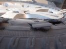
05 No doubt the tyre is flat275 viewsThis is the view of the flat tyre. Again, didn\'t think it anything more than a "normal" explosive blowout, as the tyre was about 90% worn, we were heavily loaded, it was 45 deg C, and driving 105 km/ho on a rough dirt road in the outback.
|
|
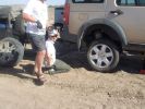
06 Spare tyre on and still suffering from hot wheel nuts296 viewsManaged to get ultra hot wheel nuts back on the spare (using the original 19" D3 wheel, vs the 19" RRS wider wheel which blew - shown in left of photo). Pity we didn\'t note that the disk brake was EXTREMELY hot at this time.
|
|
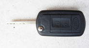
Chiave finita - Finished key18 viewsHo iserito il tutto nel nel nuovo contenitore pagato €4,00, ho incollato con la colla cianoacrilica, ne basta poca, e questo è il risultato.
I put all in the new container paid € 4.00, I glued with super glue, it only takes a little, and this is the result.
|
|

Who Left This Stick In My Car15 views
|
|

252 viewsSilverstone weekend again. My other club (RRR Ltd) do courtesy rides to raise money for charity plus we all enjoy ourselves. After 7 Range Rovers this is my first Discovery.
|
|

07 Back side of failed tyre340 viewsThis is the back of the blown tyre. It looks like any other worn tyre which has run a bit while flat. Note that we were running on wider 19" RRS wheels (have 4 19" MTRs + 1 old A/T on the original 5 wheels). Also have a rear-mount spare tyre holder which is really convenient with the wider rim and the fact that the tyre was still hot (it had some melted rubber on the other side!!)
|
|
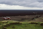
A green haven in a vast expanse of lava21 viewsThis was a great place fore some mid day leg stretcher and lunch
|
|
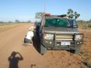
08 D3 stranded with a seized smoking wheel315 viewsAbout 1 hr after replacing the blown tyre, strange noises emanated from the stability control system and speed dropped off. Then I looked in the rear view mirror, and noted a cloud of dust along with a whiff of black smoke. This led to a very quick stop (no traffic on this route for over a week, so no worries about having to signal exiting the road). Took a look and WOW. The right rear wheel was glowing a dull red colour, and burning rubber smoke was wafting from the red glow over the fuel lines.
|
|
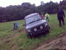
"Hold on lads..., I\'ve got an idea..."54 viewsThis angle tells you some of what could have been a bit of a tumble...
|
|
DickieDisco trying to decide if this is a better way down...48 views
|
|
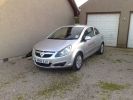
This years gutless car of the year is...66 views
|
|
Highlift mount added27 viewsHighlift mounted in this position allows for any length with out overhead clearance issues if stood upright
|
|
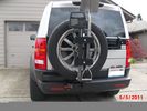
This is how to make it all work. Backup sensor on carrier43 viewsHighlift, ax and shovel. Yes they are matching colors. What else?
|
|

09 Starting to remove the seized brake assembly296 viewsBy this time we\'d poured about 8l of water on the dull-red glowing and burning wheel assembly (too close to 140l of 98 octane petrol). Sudden cooling cracked the disk brake which showed mangled park brake parts. How to remove a brake disk without the right star fitting? First remove the caliper then get a sledge hammer?!!
|
|

Is this Simon?205 views
|
|
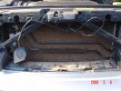
Removed Radiator Cover....wtf!!214 viewsThis gave me a few concerns
|
|

The s2a could not make this one - too deep.446 viewsGot towed through with a dead engine by a Tdi Defender - Betsy is petrol and needed a gallon of WD40 to get going after this!
|
|

10 Cracked smoking parking brake drum338 viewsNote the crack in the face of the brake. This showed mangled parking brake springs and other bits. Also a bit of melted rubber was drooling out of the crack. Started to remove the brake caliper and enjoying the flies in 45 deg C heat. Ah, the wonderful Aussie climate in January.
|
|
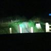
all lights switched on 79 viewsthis is the Bixenon with LR HID converted spotlights and the rigid SR40 lightbar switched on
|
|
First Thing this Morning :-)109 views
|
|
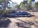
The tyre hill182 viewsWe had to drive over this without stopping. Made it, no problem :)
|
|
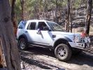
off-camber hill352 viewsAnd no, I wasn\'t hanging my arm out to balance the car - I was stopped at this point waiting for the Jeep in front to try and finish. It was a pretty steep off-camber slope!
|
|
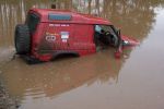
bit of water70 viewsdidnt think it was so deep. I got my feet a little wet. Car is still running and it also survived this and is still in use now. Bet a Disco 3/4 wouldn't work after this.
|
|

This picture was taken with garage doors closed.42 views
|
|
This guy has been waiting for a long time437 views
|
|
Will this stay the same for another 2000 years?126 views
|
|
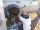
11 Lesson in removing a jammed brake assembly in the Outback378 viewsSpent the next 4 hours doing this to my D3. Gave the photos to Land Rover dealer and they did not think this constituted abuse of the vehicle. I thought that was charitable, but if we hadn\'t done this, the tow back to civilisation would have been even longer.
|
|
Whats this for?203 views
|
|

12 Half way through removing a jammed disk brake in the Outback296 viewsThis was just before breaking the sledge hammer. Note we luckily carried a spare hammer. Ended up using (or breaking) every tool we had on this little repair job. Bed sheets are a good way of gathering the bits to show for the inevitable warranty claim.
|
|
Antenna Mount462 viewsBracket mounted using existing holes behind the grill. The design of this bracket is listed elsewhere.
|
|
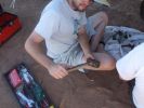
13 How to care for tools303 viewsWhat happened to the sledge hammer after 2 hours of beating my seized and cracked disk/park brake assembly to bits. Now down to 1 hammer remaining. At least by this time it was getting cooler (down to 40 deg C)
|
|

Virgin Snow134 viewsWent for a play in some new snow so I could practice and get my driving style right on close to zero friction surfces. Hard to tell from this photo, but car is parked on a 1:6 slope heading uphill, with hard packed ice under the fresh snow covering. I stopped here to practice my hill starts on ice...I was there for some time :)
|
|
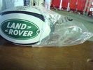
Rugby ball prize16 viewsWon this at the Dubai 7's in 2010. The LR stand had a competition. You had to push a LR4 over a something like an uphill speedbump. A modified bullbar resembling a scrumming machine allowed 3 people to touch, engage and push the beast over the bump. Me and my 2 kids - with a little bit of help, managed it and for our trouble got this ball !!!
|
|
![Filename=15082008064 [640x480].jpg
Filesize=73KB
Dimensions=640x480
Date added=15.Aug 2008 15082008064 [640x480].jpg](albums/userpics/12862/thumb_15082008064%20%5B640x480%5D.jpg)
In Disgrace100 viewsThis is where its been for 3 weeks &3 days waiting for the parts to arrive from England. later that afternoon we aere able to take her home. Civilation at last :)
|
|
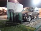
The obstacle...14 viewsThis what we had to push. You cannot believe how heavy this is. It looked easy, but let me tell you, I have seen many groups of 3 young tough guys curse and sweat...
|
|
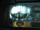
This is a H7R bulb fitted into the same headlight - look at cut off and no glare116 viewsPerfect like OEM what more can i say
|
|
This is a normal H7 HID bulb installed in a BMW headlight to show glare above cut off line99 viewsThis is what the light pattern is that causes glare in most retofit applications including some projector lights. this is in fact a projector headlight on a BMW but the old projectors were only actually half projectors and half reflective bowls. the beam pattern should be clean cut like this ___/
|
|
H7R Headlight retrofit H7R HIDS4U notice no light in bottome half of the bowl98 viewsThis is how a retofit HID should look in a reflector headlight
|
|
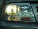
halogen bulb - some overspill but as its one third as bright this is not seen as glare. but add 100w bulbs and you will get glare94 views
|
|
This is the Standard Hi-Beam only (Bi-Xeons)32 views
|
|
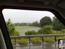
Area of the new housing expansion south of Swindon.144 viewsFlood plains will be flood plains - insurance anyone? Oh sorry forgot; all top 8 insurance companies refused to insure a house in this area, so the developers are going ahead building anyway...
|
|
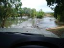
D3 in the Mary River Flood plains47 viewsIn this part of the world, on the flood plains out to Kakadu, you never get out to wade a creek first as the theory says you should. If the water isn\'t clear, like it was on this causeway, and it is this wide, you either wait for someone else who is braver than you to cross first, or you turn around and go home. These rivers are full of estuarine (salt-water) crocodiles, and they are starting to reach 7 metres in size in some still rare instances. However, seeing as a 2.5m crocodile can kill a grown man,
|
|
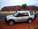
D3 in the Red Centre52 viewsParked opposite Uluru, or Ayres Rock, in April 2009. This is autumn in this part of the world, and the desert is getting cold over night, so there is a brisk wind blowing at sunrise.
|
|
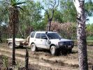
D3 in Kakadu National Park, on the track into the Alligator Billabong47 viewsThis whle area is down on the flood-plain, so in the Wet it is all under a few inches of water. In the dry it has a hard but brittle surface, which is then chewed up in many places by the feral animals with hard hoofs such as buffalo, pigs and horses. This then turns the track into a big dust bowl which is primarily bull-dust - a soft fine powder like talcum powder, which can be many feet deep, and gets into everything. The cover on the trailer is actually black.
|
|
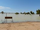
We drove this track in 2008 - East side of 'Big Red' Simpson Desert23 views
|
|
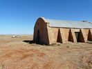
This was Australia's largest Shearing Shed - Cordillo Downs SA26 views
|
|
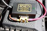
131 viewsTraxide SC80 brain modified. Cut the studs down to the nuts and removed the rubber cover. Had to do this as otherwise it wouldn't fit comfortably and would squash the brake vacuum pipe
|
|
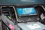
108 viewsTest fitting the screen. The bottom edge of the rear cover of the screen has been already dremeled off in this pic, notable as the circuit board can be seen.
|
|
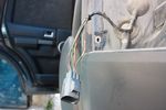
94 viewsReverse wire stripped. I then soldered the wires which I need to this wire and close up with self amalgamating tape. This way I don't damage any original wires (except for the insulation) and it's easily reversible by desoldering
|
|
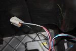
109 viewsThis is the plug for the accessory socket at the rear of the cubby box. On commercial D3 such as this one, there is no accessory socket so this plug is unused. I tapped into the 12V wire as an ignition feed. This will feed a relay coil which opens up power from the aux battery. Like this I can still retro fit and make use of the accessory socket later on.
|
|
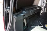
79 viewsHole for 12V accessory socket. This hole has a blanking plate on it on Commercial D3s. It just needed to be filed down in some areas to fit the socket I bought.
|
|
91 views12V socket done. This is permanently powered by the Aux battery. Another one was done on the other side, though that one required drilling the hole with a 29mm hole saw as there wasn't an unused hole on that side.
|
|

63 viewsCables grouped together and routed neatly. Cable sleeving can be seen cable tied to the VGA screen cables at this point
|
|
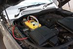
124 viewsOptima Yellow Top in battery box. This is the version with side terminals so there will be some modifications to be done to fit
|
|
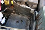
112 viewsDue to the side terminals protruding out the side and affecting the battery clamp, I found the battery will fit better if it could be pushed a few millimeters towards the engine. This lip will have to be removed.
|
|
This mornings snow24 views
|
|

Glenridding this morning31 views
|
|
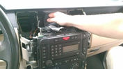
difficult to remove this pocket using normal tools...18 views
|
|
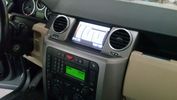
Chinese touchscreen + GPS + USB reader + Bluetooth + DVD32 viewstrying to install this touchscreen
|
|
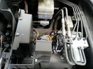
whas31 views this box?
|
|
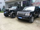
big jeep28 viewswent to collect my optima battery...this was in getting a new wing fitted
37" wheels are quite big...
|
|
My MSV2156 viewsNeed more help to get the most out of this tool.
So far used for fault code reading, 4x4 display, suspension tight setting before wheel alignment,
|
|
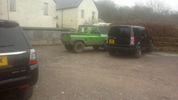
Shouldn't every pub car park look like this108 views@ The Carew Arms Crowcombe Somerset
|
|
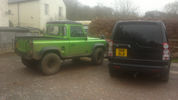
Shouldn't every pub car park look like this!107 views@ The Carew Arms Crowcombe Somerset
|
|
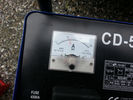
Amps43 viewsThis picture shows how mutch my disco uses while programing the engine management ecu
|
|

what plant22 viewswant to find out what this plant is and how best to control / remove it from garden
|
|

rainbows19 viewswalked past this....side "vents"also tricolour.
|
|
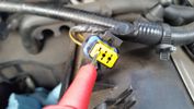
Test probe measure voltage18 viewsDo NOT insert the test probe into the connector as this can damage the terminal.
|
|
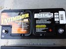
Deka 9A49 AGM Intimidator327 viewsThe Deka 9A49 AGM Intimidator makes an excellent primary battery alternative to the factory or Interstate. Made in US of premium quality. This is an excellent match with the Traxide system w/another Deka or Yellow Top optima.
This will behave properly in your D3/4 LR3 with slightly less wear and tear on your alternator.
|
|
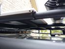
solar panel install356 viewsAt least at this point, I mounted it by using Clear Silicone RTV. This stuff is kind of like glue, but can be removed. If it doesn't hold up after curing and driving, I'll remove it and come up with another plan. I used heavy cable ties on the 4 grommets, in case it lets loose, it won't take out my wiring and the car behind me. 2 Panels are dandy like this, but I don't want to permanently block the roof space. Grape Solar to power my snomaster fridge
|
|
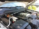
Traxide USI-160 Install515 viewsOverview picture of Traxide USI-160 upgrade install. This was an upgrade from the SC80 which performed flawlessly. The USI-160 had two relays and can deliver more amperage. As a result, the wiring was upgraded to 4/0 Welding Cable (warn) and heat shielding was added. The unit performs flawlessly to support 2 HAM Radios, Fridge, etc. Like me https://www.facebook.com/DifferentialPartsUS
|
|
Wiring342 viewsThis is the final wiring configuration. It shows the dual battery wiring, 75A wiring run to the boot, the winch and in the lower right you can see a few turns of coax with a snap on ferrite near the base of a VHF Antenna.
|
|
Thread upload26 viewsOne in a million shot. This happened while wheeling.
|
|
Is this a Disco bit?4 views
|
|

3D Printed Samsung Galaxy S5 Phone Mount21 viewsDesigned to fit a Brodit Clip Mount (in this case one for an Isuzu DMAX)
|
|
shes home!33 viewsfirst day at work after picking this up.
|
|
this is mine5 views
|
|

Front Differential Description and Operation1543 viewsThe 4 page pdf describes of the operation of the front differential plus displays an exploded view of the front differential.
The fill plug is item 36 and the drain plug, item 8.
It is suggested one first unscrew the fill plug before unscrewing the drain plug - and it might take two different wrench sizes, hence get this detail sorted out before any oil drains out.
|
|

Anti Lock and Traction Control description and operation.1986 viewsNote on page 6 of this 17 page pdf the significance of the Steering Angle sensor mounted on the steering wheel shaft. The paragraph regarding the plausibility check as related to the brake pedal being not depressed is why the clean operation of the second set of contacts on the brake switch matters so much.
|
|
This road isnt on a bus route!124 viewsWent to see how my new house is looking in Czech Republic, this is one of two roads out of the village
|
|
Riverside in Durham this morning62 views
|
|
Hunting289 viewsCALENDAR 2011 ENTRY
This is in Puerto Rico. Easy local trail. Point of view of an iguana :-)
|
|
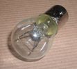
Land Rover Stop Tail Light dual filament bulb nominal 12 volt 21 / 5 watt filaments1427 viewsThis is the Land Rover part number 264590 dual filament bulb, (P21/5), that inserts into the upper two tail lamp receptacles. In the upper one, both filaments function, in the lower one, only the 5 watt tail light filament functions.
I regard it as not a good practice to routinely switch bulbs when the tail light filament, (5 watt), burns out on the lower bulb. The broken filament can jiggle over onto the brake light filament, (21 watt), and short the circuit to ground or something else not predicable.
There are also arguments to say that quality control is better on the Land Rover marketed bulbs than say far east sourced bulbs. Filament construction, and hence resistance can vary and mislead the current sensing circuits monitoring the signal light systems. Also when the bulbs are properly installed, all filaments should be standing vertically and not at any slope.
These are the sort of obscure circumstances that can lead to false trouble messages on the display, dropping to the stops, and subsequent concerns - all over a tail/signal light bulb.
For example, the filament life of both the tail light and the brake light filaments in the P21/5 bulb is significantly less than the USA common 1157 dual filament bulb, (1000/250 vs 5000/1200 hours); brightness in the P21/5 is a bit more, (3cp/35cp vs 3cp/32cp where cp is candle power), but current consumption is oddly less, (0.44a/1.86a vs 0.59a/2.10a where a is amps). It is the quest for efficiency vs maintenance trade off.
|
|

This photo says it all116 views
|
|
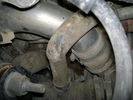
Charge Air Pipe - turbo end.101 viewsThe maint manual identifies releasing the pipe hose clip in the center of the photo. Pity who ever built this engine Put the hose in such a position that access to it was near impossible. I released the other clip at the turbo end of the flexi hose. Easy to get to but a right git to release the hose of the turbo.
|
|

Air con pipe65 viewsIts the brown pipe in the center of the photo. To remove this first you need to remove the "charge air cooler inlet hose" to allow access to the air con pipe securing fixings. But with the "charge air cooler inlet hose" disconnected it can\'t be removed from the veh because the air con pipe is in the way???
|
|
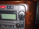
position of buttons for Parrot phone102 viewsthis can be put basically anywhere as it connect via bluetooth to the rest of the system. It is self powered (lithiam battery in it) so just stick it anywhere with no requirements for finding a live wire etc
|
|
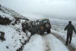
2 90's off at Lochearnhead208 viewsGuess this was why we turned round.
Photo pinched from SLROC website!
|
|

Engine Accessory Drive Description and Operation882 viewsThis 2 page pdf shows both belts for the 4.4L petrol V8; the primary serpentine belt, (the long one), and the shorter secondary that drives only the radiator cooling fan.
The various accessory pulleys the two belts are each associated with are numbered and an included table describes each.
When replacing belts and pulleys, count the number of grooves on both your old items and your new replacement parts. It has been known for an pulley with the wrong number of grooves to come with a replacement part or the replacement belt has the incorrect number of grooves; hence make certain the groove count on the new parts are the same as the removed items.
|
|
fun in the mud317 viewsCALENDAR ENTRY 2011
This is in Puerto Rico. The area is called \'cielito\' (little sky).
|
|
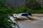
Carwash20 viewsThis seems a long time ago - down on the east coast of Oman
|
|

Leaning163 viewsThis is an example of the leaning against the mud walls.
|
|

3 Point Hitch on Series 90152 viewsUsually one sees the Series units with just a conventional field plow hooked to a drawbar hitch, tractor style. This jpg however is the full meal deal - a 3 point hitch, probably off a Fordson tractor, in the long tradition of Ford/Land Rover cooperation.
|
|
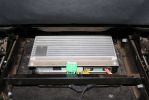
03285 viewsStock amp, underneath passenger front seat. In order to integrate the factory head unit with the V1000 we had to go through the stock amp. This is because of the MOST (fiber optic) connection between the two.
|
|
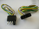
4 pin NAS flat connector from NAS small trailer382 viewsThe connector with the three exposed pins is the end that would commonly be located at the trailer hitch end, (front), of a small NAS lightweight trailer that has no electric brakes. This plug would connect into the flat 4 pin connector at the rear of the 3.
Note the order of the pin functions and wire colours: White is ground; the next pin is for tail/marker lights using the Brown wire; the Yellow conductor is for the left turn signal, and the far pin uses the Green conductor for the right turn signal.
There is no separate brake light conductor as NAS spec vehicles most often combine the brake and signal light functions to the same bulb filament rather separate filaments in different bulbs. The LR factory harness resolves that design difference.
Fortunately, the Land Rover NAS assembly pin order for the 4 pin flat plug maintains the above described conventions.
|
|

Air Distribution and Filtering Systems2083 viewsThis is 3 page pdf with coloured drawings of the air distribution ducting for the front air system.
Also included is a sketch of the pollen filter location within the front heater ducting. Note that two types of filters are available: a) the cheaper dust/pollen filter and b), the activated carbon filter that removes smells from the air. Installing the more expensive activated carbon filter means you never smell a cattle truck or chicken farm again. It really works.
|
|

Front Heater Doors Description and Operation1396 viewsThis 6 page pdf shows with coloured drawings the air flow thru the front heater as well as discusses the operation of the various air flow doors.
|
|

Air Conditioner Specifications 4.4L V81569 viewsThis 2 page pdf is just the specifications for the AC system. The refrigerant type is R134A.
Note that when topping the system up, it can be a good idea to include some of that ultra violet light dye that will glow to show leaks and loose fitting.
|
|

Rear Area Climate Control System1161 viewsThis 14 page pdf describes how the rear heating AC system is supposed to operate in conjunction with the front system.
The air transfer ducts are shown as coloured sketches as is the air flow within the rear blower setup.
|
|

Air Conditioning and Heater Control Components2425 viewsThis is a 21 page pdf that really explains how the air system is supposed to work. Discussed are the exterior ambient air sensor, where and how it operates; the interior temperature sensor as well as humidity sensor.
|
|

Alternator and Regulator Wiring Diagrams, TDV6 and petrol V8 and V61989 viewsThis is a three page pdf that shows the alternator and regulator wiring for the petrol V6, petrol V8 and TDV6. The pdf can be either printed or by right clicking on the displayed pdf, rotated as required for viewing.
Of interest is that the regulator gets its instructions primarily from the Engine Control Module (ECM) and only secondarily from the vehicles electrical buss. The conductor from the battery thru the 5 amp fuse F20E is to provide initial power to excite the alternator at startup and then secondarily, to instruct it if the PWM signals were not available. Primary instructions to and from the ECM are thru the two other conductors via a digital like Pulse Width Modulated (PWM) signal.
If F20E, the 5 amp engine compartment fuse box fuse is blown, the red alternator light on the dash will be illuminated. This means that the alternator could be OK, but if the F20E fuse is blown, no electricity will be generated. Hence check the F20E fuse if you get a red ALT light or some indication of the alternator not working.
Regarding operation of the red ALT light on the dash, it is not the regulator within the alternator that tells the red light to illuminate, or not, but instead the ECM. This is the reason the red light does not function in the same manner as with older vehicles. With the 3, sometimes you have illumination and sometimes not depending upon what the ECM is thinking. What this means is that you can have an alternator that is failing but the red light does not illuminate as the ECM is compensating for reduced alternator output - maybe by draining the battery and or cutting back on vehicle electrical loads such as shutting off or cycling the radio amplifier or heated seats.
|
|

Fibre Optic MOST bus plus CAN, LIN, GVIF and SLIN buses1539 viewsThis 7 page pdf introduces the fibre optic MOST bus, (the orange coloured cables), the two high and medium speed CAN buses, the Gigabyte Video InterFace, Local IntercoNnect, and Security Local IntercoNnect buses.
|
|

Alarm System description and Operation1052 viewsThis 9 page pdf explains in detail how the anti-thief, (alarm), system is supposed to operate. The system uses the door ajar switches to provide alarm system signals; as such there are few separate contacts related to the alarm system only.
Page 6 of 9 is of particular interest as it describes the trigger log that is accessible with the dealer T4.
|
|

GPS NAV system components and operation999 viewsThis 16 page pdf describes the operation of the GPS navigation system and provides pin outs and equipment layouts. The GPS antenna amp and location is also shown.
|
|

Wipers, Front and Rear, plus Washers description and operation.818 viewsThis 17 page pdf describes how the wipers, front and rear, plus the washers are intended to operate. Also described is how the rain sensor is designed to function along with a table of the wiper delay timing parameters.
|
|
283 viewsCALENDAR 2011 ENTRY
This is in Puerto Rico. LR3 parked in the shade while we hang-out at a secluded beach that can only be accessed in 4x4.
|
|

Siemens VDO Piezo Common Rail injection PCR 2.321 viewsAfter sales info and exact system discription.
Also fault finding and repair.
This is for Ford 3litre 4 cyl. engine ,Ranger 3.0 TDCI, but Disco 3 is the same with 6 cyl.
|
|
Ooops, found the mountain bike trail. KW Hydrocut16 viewswe were out one day and suddenly I seemed to recognize the power lines, and the fact that the mountain bike trail runs alongside the lines.
This is obviously a wide section of trail, but it's still the KW Hydrocut mountain bike trail.
|
|
6mm Heat Shrink colours 362 viewsI decided to colour code the tubing so I used 6mm electrical heat shrink.
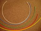
As there is no apparent colour coding re the 3, I tried to emulate the P38 coding; #1 LR red, #2 RR blue, #3 LF yellow, and #4 RF green. This was not doable as both left side air springs have green coloured tubing coming off the top of the front and rear air springs. I therefore arbitrarily chose the Left Rear to be red; Left Front green; Right Front yellow; Right Rear blue; and for the air compressor supply line, White coloured heat shrink. Since two new lines tie into each air spring line, I made the line between the air spring and the FASKIT, a single solid colour, and the line from the FASKIT to the valve block, White, plus the related appropriate solid colour.
|
|
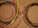
6mm PA12 grade nylon tubing with heat shrink applied 543 viewsShows some of the 6mm air line with heat shrink applied to one end of tubing. Shrink will be applied to the other end once field cut to length. These four tubes, each about 20 ft (6m) long, feed to the rear. Re the front air lines, (not shown), four additional lengths, each about 10 ft (3m) long, are required plus one more 3 metre length for compressor air. The 6mm tubing is a Nylon product specified as PA12. There is also a very similar Transport grade PA11 material, however it seems that PA12 is the more common Transport grade now in use. Also the applicable DIN standard seems to be both DIN 73378 and DIN 74324 for the nylon tubing. The working pressure of the 6mm tubing is about 27 Bar and bursting 82 Bar @ 20C. This is for the 1mm nominal wall thickness material, (4mm ID, 6mm OD).
|
|

Tools from dealer110 viewsThis is a cel pic of the tools from the dealer for install and removal of control arm bushings. minus one broken tool.
|
|

129 viewsThis is the installation guide from the manufacturer
|
|
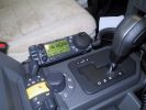
Ham Radio454 viewsThe remote head of the Icom IC706 mounted on a block of wood shaped to fit the coin holder. This is an HF, VHF and UHV transceiver.
|
|
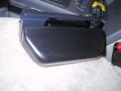
Ham Radio448 viewsThe remote head of an Icom IC706 was mounted on a piece of wood shaped to fit into the coin holder. This is quite a tight fit and does not shake loose. The radio is mounted under the driver seat.
|
|
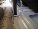
Antenna Bracket388 viewsThis was bent from a piece of 3mm x 25mm alloy flat bar. I used automotive grade double sided tape and two screws to fasten it. I have a dual band VHF/UHF antenna on this bracket
|
|
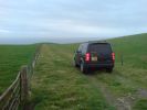
Farm Track204 viewsThis track across the farmers field leads to the \'Cliff Drive\'
|
|

KLB from above.27 viewsI'm lucky enough to live in this beautiful part of the world. My house is in this picture.
|
|
20 viewsThis is the access hole, one on either side.
|
|
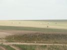
View across the plain113 viewsThis was a shot across the plain taken with my KM Z5 at maximum 12x optical resolution - these vehicles were a long long long way away!
|
|

Add A Circuit Littelfuse Data sheet2278 viewsThe switch connects to what Littelfuse brand calls an Add-A-Circuit model FMH200BP which is an adapter that plugs in place of a Mini fuse and then has space for two Mini fuses, (original and a second one). In this install, only the original 5 amp fuse was used - adapter was so as to route power from fuse box thru fuse, then rocker switch, and then back to fuse box.
Before you install the Add A Circuit for this application, take an ohm meter and trace out the circuit path of the four slots that fuses could insert into. The path is more complicated than one might first think. As such, the orientation of the fuse holder in the socket matters for this application - that is for a circuit diverter, rather than accessory adder.
|
|

Land Rover Aerial Fin images for both Glass and Metal Roof Disco3 / LR3863 viewsAs well as the two different fins, this pdf also shows the plastic blanking plate for glass roof vehicles where no fin is installed.
The glass roof fin is secured by two security screws from the top into a plastic frangible glue on gasket. The hope is that when struck, the fin will shear off and not crack the glass roof. Re the metal roof design, the fin is secured from underneath via two nuts.
The pdf also shows the various electrical bits related to the antennas. In the UK, the fin would house not only a cell phone antenna but the TV and satellite radio antenna electronics as well; in the States, the Sirius sat radio antenna and a G type cell phone antenna if the phone kit was installed would reside within the fin. The SAT NAV GPS antenna is located within the High Mount Brake Light plastic mounted to the upper rear hatch.
|
|

Fin cell phone aerial drawing190 viewsThe factory aerial for the factory NAV / GPS on my 2005 HSE is within the high mounted stop light lens at the top of the upper hatch door. I do not have the factory installed phone kit, and as such, do not have the fin installed; instead there is just a plastic blanking insert to fill the cell phone aerial wiring hole in the metal portion of the roof; hence this requirement for an "external" cell antenna. For those that do have the fin on their glass roof, the fin is screwed on to a glued on plastic gasket, (sort of), and not bolted thru as per the metal roof 3's.
|
|

Almost a Bridge10 viewsAnother bridge this one we had to rent the branches and use our sand ladders
|
|
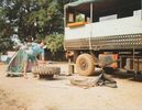
Puncture repair13 viewsI think in total we did this about 10 times, in 6 months, not a bad record, but not easy in the Bush !!
|
|
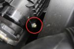
Air Box Lower Securing Bolt1072 viewsThis bolt must be undone in order to remove the air box. It is long and tricky to get out and could be dropped easily.
|
|
Air Conditioning Pipes (file 2)808 viewsShows location of front-to-rear air con pipes behind NS front wheel. You can just see the Vredestein tyre. The pipe connectors are tucked in behind the wheel arch inner cover. This has to be partially removed for access to bolts holding pipes together.
|
|

Alternator female plug looking down into top373 viewsThis shows the plug connected to the alternator wiring harness looking down into the top of the plug.
The cavity marked 1 is the AS or BATT SENSE and the wire colour most likely has Brown/Green on it.
The cavity marked 2 is the RC or ALT CON and the wire colour most likely has Red/White on it.
The cavity marked 3 is the L1 or ALT MON and the wire colour likely has Green/White on it.
I say "most likely" as the wire colours are not always the same on all vehicles.
Also the terminal 1 conductor destination is more likely C0570-175 rather than per the jpg.
The #3 pin is located closest to the big B+ terminal.
|
|
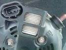
Alternator Plug and B+ terminal918 viewsPictured is the rear of the older Land Rover part # YLE500190 alternator showing the shiny cooling fin of the Regitar VRH2005-142 regulator under.
The first pin in the far left side of the connector is numbered #1 in the LR electrical wiring diagrams and is Battery Voltage Sensing (BVS); the middle pin, #2 receives a Pulse Width Modulated (PWM) signal from the Engine Control Module (ECM), and the right pin, #3 carries a PWM signal back to the ECM. Terminal Pin #2 on the LR wiring diagrams is called Alternator Control or ALT CON; Pin #3 per LR is called Alternator Monitoring or ALT MON.
Pin #1 is similar to what in older designs used to be called A or Batt, but is now called by Denso, S, AS, or Alternator Sensing for this design. Pin #1 also provides power to excite the alternator at startup until the PWM instructions over ride the battery voltage info. Land Rover calls the electronics under the pins a Smart Regulator, ironic, as it has to follow orders from the ECM rather than give the orders - new age thinking I guess. This is different from older design internal regulators that look at just the battery or the electrical buss voltage and then decides itself what to do.
It is almost like we are back to the external regulator designs of old, except that the ECM may decide that instead of telling the alternator to make more power, to load shed, and hence shut down the heated windscreen, seats, or whatever other electrical loads it decides are appropriate. My view is that the "smarts" are in the ECM and that the "regulator" should be regarded if not dumb, then as being a slave to the ECM.
|
|

how to install Altox WBUS-4 in engine room on Discovery 395 viewsthis is to show how to install the Altox WBUS-4 in engine room of a Discovery 3, but i would recommend to install it inside car in footwell, see other PDF in this album
|
|

Amp Drawing53 viewsThis is how many amps my vehicle was using when the ign in possision II. Lights where off, radio off,hvac off Crazy?
|
|

176 viewsThis photo was "Autostitched" from 7 individual ones.
|
|
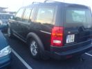
Got back to the airport after a few days in London to This!!!281 viewsThis is one of the many reasons we sold our first D3........
|
|

Nav System Error Message20 viewsThis is the error I got onscreen after trying satnav upgrade from a dodgy copy. Same error then using old disc. Solution was to use a 'good' copy or the same type as the duff upgrade disc.
This isn't a duff photo - the screen really does have a double image of the text.
|
|
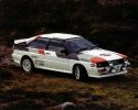
My other 4x4447 viewsI'd sell my soul before I'd sell this one!
|
|
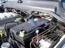
BCI Group 40R Deka 640RMF battery showing vent hose run forward to windshield washer reservoir area 1430 viewsRecessed post "Euro profile" battery to "match" OEM and stock Land Rover bracket; note that the Traxide SC80-LR module is mounted at an angle to allow for the main cable to sit under the cover so cover still closes.
The battery is a nominal 7", (180mm), high, but sits on a 1" battery spacer set under to raise the bottom front end of the battery such that the approx 11", (290 mm), length of the BCI 40R battery rises above the angled plastic nibs at the forward end bottom of the case front; hence sufficient space, (1/4", 5mm) remains at the brake reservoir end.
Also the 40R battery does not have hold down "flanges" on each end; on the sides yes, but not the ends so no additional length is required.
When I had to replace the 40R, this time I installed the shorter, (9.625"), taller, (7.5") Interstate BCI 47 / DIN H5 battery which eliminated the spacer on the bottom and better fit the stock LR tie down bolt lengths. Deka also has a BCI 47 / DIN H5 that would work fine as well.
|
|
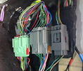
AUX wires?25 viewsIs this the AUX wires to tap into?
|
|

A Pillar Black Plastic cover install pdf - new type.1038 viewsThis 3 page LR pdf explains how to install the newer A pillar plastic covers and avoid instant water leakage as a result of the new design.
|
|
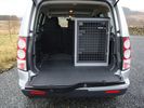
B24 TransK9 Dog Transit Box for Discovery 471 viewsThis box is designed specifically for the Discovery so that the 6th seat can also be used.
|
|

Stick This Fish In Your Ear29 views
|
|
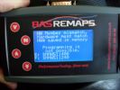
BAS remap interface after dealer software update287 viewsBAS remap interface after dealer software update,This is what you will be presented with after the dealer updates your cars engine software.
This is no problem IF you have returned the car to standard before the dealer visit.
When faced with this screen it will show you tht the dealer has changed the software and NOT let you put the BAS mapping back on your car because of the differences.
|
|
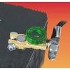
Battery Disconnect Wirthco 20308 Knob Top Post 890 viewsThis is a battery post style disconnect, usually for the negative terminal. There is a hole drilled in the round end off the battery so that flat terminal can be attached as well as the normal battery post terminal. I did not use this hookup arrangement, however I show it for information only.
|
|

Caterpillar Battery Size cross reference chart and battery profiles including post layout752 viewsThis pdf has a dimension, (metric and inches), cross reference chart plus another sheet that provides BCI and DIN cross reference numbers and shows post locations plus bottom ridge tie down locations, (or the lack of).
This data was for me, hard to find, and helps one in selecting a suitable physical size of Aux battery for the space available.
|
|
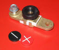
Battery Disconnect side post with + & - caps, top view617 viewsThis disconnect is designed for side post batteries. It can be used on either the + or - terminals. It can also be installed at the "other" end of the battery cable as well. In my install of the Aux battery, I installed this on the negative ground cable where the cable attaches to the body sheet metal. I have never used it but it seemed like a good idea at the time. The main battery hookup is pure stock.
For the hot side of the Aux battery, an Anderson PowerPole was used inline for the cable between the Aux and connecting to the spare bolt hole at the + post of the Main battery cable.
|
|
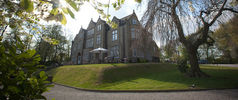
Woodlands Hotel6 viewsGreen Oval Garage would like to say thank you to the Woodlands Hotel in Leeds for allowing us the use of their beautiful grounds for all our future photos shoots.
Woodlands is one of the finest luxury hotels in Leeds. This boutique hotel is set in beautiful landscaped grounds on the outskirts of Leeds city centre, just 2 minutes drive from junction 27 of the M62 motorway, with 23 individually designed bedrooms and an award winning restaurant. Packed with character, this lovingly restored hotel is only three miles from the vibrant, cosmopolitan city of Leeds with superb nightlife and unrivalled shopping.
Woodlands also offers a stylish and contemporary functions venue for all kinds of social and business events. Our three stunning event spaces are suitable for everything from wedding ceremonies and receptions, to corporate meetings and events. The permanent marquee, attached to the hotel, can accommodate up to 150 for dining and 200 for evening parties and receptions, making it one of the most elegant settings for a wedding venue in the Leeds area.
For more information or to make a booking, please contact us on enquire@woodlandsleeds.com or 0113 2381 488
|
|

Thread upload3 viewsImage uploaded in thread 144213
|
|
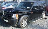
Bent Black Betty228 viewshard to believe that in this condition she\'s a write off, what got her was the cost of tricknology repairs, seatbelt pretensioners, airbags etc etc, & declining values, repair estimates €12500, value €13000. a no brainer really
Note TASTEFULL G4 sticker
|
|
BFG used a bit57 viewsThis is more like it...
|
|

You know this is going to hurt......100 views
|
|
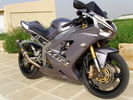
New Bike42 viewsGot bored not having my D3 with me so I went made one day and bought this!
|
|
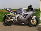
New Bike36 viewsGot bored so I got this..
|
|

Bin cover removed to expose plastic moulding covering buzzer.10 viewsI guess this moulding is helping to retain the bin cover when in place rather than to "protect" the buzzer but that is also what it seems to do. In any case, unscrew the two large screws and lift moulding off exposing the buzzer.
|
|
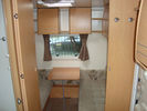
27 viewsthis converts to my sons bedroom and the door shuts across so we dont disturb him at night
|
|
where this bit go156 viewsproject 5ser heater blower..... joy
|
|

bmw32 viewsget used to seeing this
|
|
This definitely needs investigating.....175 viewsI had already picked this BOAT out on the O/S map but now I\'ve seen it in the flesh, it needs to be investigated
|
|

B&Q 15% Off This Weekend101 views
|
|

Brakes Description and Operation2229 viewsThis is a 17 page pdf that describes the operation of the various braking systems: the ABS, CBC, DSC, EBD, ETC, EBA, EDC, and HDC. Also discussed is the yaw rate and lateral acceleration sensor as well as the steering angle sensor.
|
|

Brake Light Switch, Find, Remove, and Install Instructions 7851 viewsThis is a two page doc outlining where to find the brake light switch, how to remove it, and then install the new one.
Note, do not move the brake pedal when removing or installing the switch. Let the brake pedal hang where it wants to. The switch design is actually cunning, and as such is supposed to make the removal and install fool proof. Hence if you think too much about it, you can wreck the new switch.
If you want to inspect the interior of the switch, wait until you have removed the old switch. You can then just unsnap the blue from the white to get it apart. Inside, the switch is quite simple, (no circuit boards), but it will probably show black dust from failing contacts.
I think the reason the switch fails is that the Normally Open, (NO), contacts of the brake light contacts were made too light to carry the current load for make and break of the tail light filaments. I also think the black dust created then fouls the Normally Closed, (NC), second set of contacts for the ABS circuit. As such, the Normally Closed contacts become intermittent in operation and display as a fluctuating open and closed circuit condition to the ABS system when the ABS should be seeing a steady closed circuit. Hopefully the replacement switch contacts are more robust and may be as I recently replaced my switch again just as a matter of maintenance. While in a redesign, ideally the NC contacts should be sealed or at least separated from the NO contacts, when I inspected the removed switch, this time there was no black dust present.
Probably the removed switch will have a Land Rover oval logo moulded into it, the new one, FOMOCO.
|
|
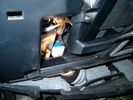
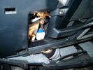
Brake Switch Visible thru Opening4973 viewsThe blue and white bit is the switch; the sort of gold appearing box,(it is really black), you will not see in your 3 as it is a Smooth Talker brand amplifier for my Blackberry phone antenna. This install is detailed in the SmoothTalker phone antenna section of my gallery.
One way to remove and install the switch is to lower the "horizontal" panel above the brake pedal as shown where the flashlight head is located. To actually remove the switch, you slide your hand thru the gap and rotate the switch clockwise 1/4 turn while watching thru the rectangular opening. Installation of the new switch is the reverse of above - 1/4 turn counterclockwise.
Before you remove the switch, note its orientation - horizontal with electrical wires to the left. That is the way it should look after replacement as well.
The second time I replaced the switch, I did it all thru the rectangular opening and did not remove the horizontal panel - that is experience helping out.
The knee kick you have to remove regardless. It is sort of hinged at the bottom so you just pull at the top and sort of rotate the knee panel and then pull upwards for two plastic "fingers" to clear the slots they reside in.
|
|
Smooth Talker Amplifier Box mounted below near steering column.179 viewsThe gold look box due to the lighting, (actually black), is the antenna amplifier located near the steering column. It can be put anyway but this seemed an OK location as I ran the antenna connector cable rearward from here to the back corner of the 3 and then up to the underside of the roof glass at the rear. The blue/white thing is the brake light switch that often must be replaced. See the Brake Light Switch file within this Gallery regarding the switch replacement.
|
|

Black Deposits on Brake Light Switch Plunger2757 viewsThis jpg I got off another forum and is typical of what one will see when one opens up the removed brake light switch. The black powder is residue from arcing of one of the pair of contacts within.
Hopefully the newer switches with the FOMOCO logo moulded into the plastic are improved from the Land Rover logo marked early units, however I doubt it.
The Ford part number is SW-6572 and/or 7E5Z-13480-A as used on the 2006 to 2009 Ford Fusion's and Mercury Milan's; the Land Rover part number is XKB500110. Cost of switch could be about twenty five dollars. A previous LR part number for the switch was XKB500030, so hopefully the newer LR part number, XKB500110, reflects some improvement in reliability.
It is possible that the new switches are better as I installed a replacement 72,000 km, (45,000 miles) later, at 195,000 km (121,000 miles). When I took the removed switch apart to inspect, it was clean inside. There was no black dust - the switch looked like new, hence they must be improved now.
|
|
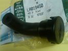
Breather Cap part # LR0194501540 viewsThis is the replacement breather cap as manufactured by the Gore Tex people, (Gore), for the engine compartment end of the front differential breather line.
You can with some difficulty, both blow and suck thru the breather filter material. The Gore Tex filter material has what are called hydrophobic and oleophobic properties. This means the filter material keeps oil in and water out, while at the same time, allowing air pressure to slowly equalize, (air permeable). Additionally, the transfer of dust, salt, and road debris is inhibited.
|
|
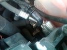
Breather Cap Installed2006 viewsThe black L shaped tube is is the Gore manufactured, (the Gore-Tex people), LR4 Breather Valve installed in an LR3. Naturally the installation looks similar to what one sees on an LR4 or RRS as the Gore breather valve is now OEM for new production.
The part number of this upgraded front differential breather valve is LR019450 and costs about thirty dollars.
|
|
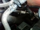
New Breather Cap installed.1709 viewsThis shows the new Gore brand angled breather cap installed. The cap points rearward to the firewall. Also shown is the cut off piece.
The new Gore breather cap is what one now sees on the LR4 and RR Sport.
|
|
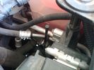
Vertical Breather Hose before cutting off OEM cap.1778 viewsThis shows the plastic vertical breather tubing and OEM cap prior to being cut off. The tubing is located on the driver side at the front near the radiator. One cuts about 3/4" to 1" off from the top. The TSB says 20mm.
I tried blowing thru the cut off piece and was not very successful. The cap seemed plugged. I am beginning to think that there was a very good reason for Land Rovers's Technical Service Bulletin, (TSB).
|
|
Grommit21 viewsIs this a free grommit low down and on the LHS of the brake servo?
|
|

Grommit20 viewsOn manual D3's this is used by the clutch. Om Autos it may be free for routing a cable
|
|
Burnt Bit97 viewsThis bit of wiring going to the connector was so close to bulkhead it got a bit burnt, Its for the clutch switch on a manual used for EPB, It will be replaced connector to pin with the wiring shown.
|
|

Even a D3 cant get through this!745 viewsPicture taken on the B974. My 300TDi is behind the photographer and wasnt going any further.
|
|
Disco3 in snow415 viewsThis photo was taken in Jan 2009 on a SLROC green road run. This was at the summint of Glen Shria
|
|
Camping by Pilbara waterhole81 viewsCan't get much better than this. So peacefull
|
|
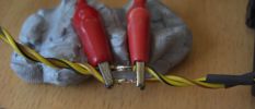
Can Pair Repair84 viewsThis is the high speed CAN bus Pair. By over twisting and keeping the repair short i will maintain the very important twist. Good soldering is a must it looks ropey in this shot but it is not, note the heat shrink pre placed on the wires to the right.
|
|

Thread upload12 viewsImage uploaded in new thread
|
|
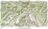
93 views4x4's only on this rough trip.
|
|
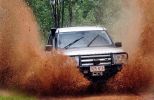
D3 on the Gold-fields Loop South of Darwin, and North of Pine Creek. 67 viewsThis is the middle of January, so is right in the middle of the Wet. Red mud. EPB hates it.
|
|
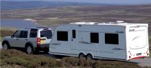
Elddis Crusader Storm256 viewsNot our actual caravan (or car) but very similar! We have a Superstorm which doesn\'t have a fixed bed at the rear like this one does.
|
|

Saw this TD5 on eBay - note the bonnet scoop and roof spoiler...318 views
|
|
Funny who you meet in the car park....227 viewsParked in a stupid place this lunchtime...
...and guess who parked next to me?
|
|

Central Door Locking Operation Description1458 viewsThis 17 page pdf explains how the door locks are supposed to operate. Note that on page 9/17, the explanation of the operation of the hood ajar switch is wrong. It operates similar to the door and tailgate ajar switches; that is when a "door" is closed, the switch is closed to maintain a ground back to the CJB. Opening the hood, door, or tailgate removes the ground breaking the circuit and hence allows for an alarm condition.
|
|
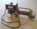
Champion C9000G winch15 viewsBrought this on a whim for a tenner.
What have I done?
|
|
Couldn\'t get up to Goyt Valley this weekend - but found some snow!470 views
|
|
Harry Potter beat this !!!217 views
|
|
This show that the angel of the radio body is diffrent from the original, hence shall some plasic be removed - I used a dremmel and removed 7 mm of the horizontal bar inside 160 views
|
|
This shows the standard radio body angle161 views
|
|
LRs stick together129 viewsA date plantation alongside a wadi in the Western Hajar mountains of Oman. My mate\'s Disco 2 in company. Cracking drive on this day some 100km off-raod through wadis and mountain graded roads. Sheer, unadulterated pleasure.
|
|
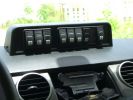
Mud UK switch binnacle453 viewsToo many switches for the roof mounted console, so this binnacle from Mud UK (desigend for the Defender) is an almost perfect match for the leather finished dash in the LR3. Switches, connectors etc bought from them too. From L - R switch functions are:
LH side mounted rack lamps
Driving lamps rack mounted
Spot lamps rack mounted
Bumper mounted driving lamps
RH side mounted rack lamps
Warn winch isolator
Rear mounted rack lamps (reversing)
Telescopic work lamp (fitted behind RH spare wheel)
|
|
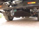
LongRanger auxiliary fuel tank357 viewsThe LR fuel tank imported from ARB in Australia with its 115 litre capacity has more than doubled the range of the car. This is important in the desert where fuel consumption increases at times to 10mpg or less. On a cruise on highways, the car now has a range approaching 850 miles. The tank fits neatly, has not affected handling in a detectable way apart from over speed humps, when a little more bounce from the rear suspension is detected! Suspension copes with the additonal loads without any problem.
|
|
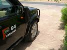
2009 MY?239 viewsThe wheelarches, door sills, and door mirror bodies have all been sprayed to match the body colour. Same as 2009 MY? I think this looks really good, and is so much easier to keep clean than the textured plastic that suffered badly out here from dust/dirt ingraining and UV discolouration.
|
|
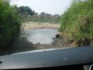
Border crossing42 viewsThis is what all border crossings should look like
|
|
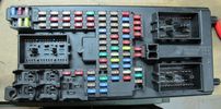
202 viewsfuse plane (this is what you see behind the glovebox)
|
|
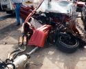
MERC CLK AMG - bit bent149 viewsThis is the short version. A bit of a head on bump did some major restyling.
|
|
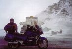
10,000ft up in the Alps!!! Honda Pan European Sept'01392 viewsThis was the first time I had ever fallen off a bike. Snow didn't help! Nothing hurt or damaged so we stopped to take a picture...
|
|
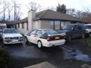
Toy box opened for cleaning468 viewsWork this out! 3x4x4, 1x4x2, 1x2x1, 1x2x0. (Hint: There is a motorbike hiding behind the BMW). SWMBOs car is off to visit the out-laws so I got to wash my toys.
|
|

COMM FAILURE in the Faultmate FCR79 viewsThis is ONLY shown if either you have a communication error or in most cases you dont have fitted on your car the module you are trying to communicate with.
|
|
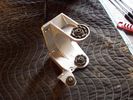
Air Compressor mounting bracket new907 viewsFound this jpg on a forum - thought it was good and is what one breaks when one jacks on the plastic air compressor cover.
|
|

This is what happens when you go too deep in a Discovery!578 viewsMy friend Dave was driving Strata Florida, after heavy rain. The Disco 200tdi was kitted for wading, with snorkel etc, but this demonstrates what happens when you submerge the bonnet.
|
|
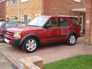
ng on the drive after a legacy of 7 silver Discos478 viewsI\'ve had silver Discos so many times now the neighbours thought that this was a loaner
|
|
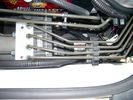
CounterAct Power supply mounted under brake lines.194 viewsThis top view shows where I located the power supply. It is attached with 3M sticky to the black plastic surface that is located under the brake lines.
When the system is operating properly, the red LED pulses about twice per second.
Some users claim they can hear a very slight hum or whine coming from the unit. My unit seems silent.
|
|
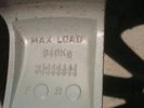
940 kg load marking on inside of spoke419 viewsThis is a typical 940 kg load marking on a Cromodora wheel rated for the 3. In this case, the wheel is the 6 spoke 19" wheel common to the HSE, LR Part # ALY72191U.
|
|
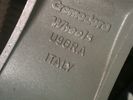
Cromodora brand marking on inside of spoke.326 viewsThis is the Cromodora brand marking on the inside of the 6 spoke 19" wheels, Land Rover part number ALY72191U. Similar brand markings are cast onto the inside surface of the spokes on all Land Rover Cromodora wheels.
|
|
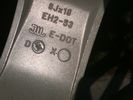
E-DOT and Japan wheel acceptance marking on ten spoke wheels.335 viewsThese are the E-DOT and Japanese wheel acceptance markings on the inside of one of the ten spokes of the 8J x 18" wheel, Land Rover part number ALY72190U or RRC500250xxx where xxx is the colour number, in this case, MNH for Sparkle Silver. There are similar markings on all Cromodora wheels for the 3.
|
|
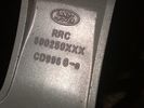
Part number moulded into spoke of 18" ten spoke. 322 viewsThis part number, RRC500250XXX is moulded into the backside of one of the spokes of the ten spoke 18" wheel. An alternate part number is ALY72190U or ALY72190U85 which relates to year and finish.
Another number is RRC500250MNH where MNH is also the finish, probably Sparkle Silver.
|
|

Crow Rash on bonnet120 viewsThis seems to be down to crows hopping around on the bonnet
|
|

C pillar cover removed to facilitate removal of bin cover.9 viewsNote the "ribbon" behind the top left corner of the C pillar cover. This is something to do with the curtain air bags, hence do not mess with it. I dislodged the cover to make it easier to pull up and extract the black plastic bin moulding. It is not necessary to totally remove it and would be what I call a big deal - seat belt, air vent and ducting as well as that curtain concern.
|
|

Dicky not putting enough effort in to this recovery57 views
|
|

Cant be a poser as he smoked his tyres to get in to this spot........ Bravery blobs 174 views
|
|
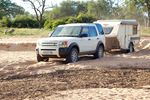
Gona Re Zhou Nationat Park Zimbabwe50 viewsThis is where I got stuck with the Defender in 2009...
|
|
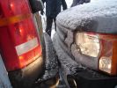
Taken from behind in the snow!!!321 viewsNot sure who bumped me..... but my car was being serviced at the time and this was a courtesy car!
|
|

170 views
|
|
Now - why did I buy this again - Ah yes, I remember now556 views
|
|
D3 High Alpine Pass450 viewsCALENDAR ENTRY
Sept.08 on the way back from Monaco towards Switzerland. The \'Col de L\'Iseran\' is the 3rd highest road in Europe and this shot is taken slightly higher than that!
|
|

Stick an LRX/F2 front end on a D3 and this is what you get...182 views
|
|
20\'s - 2nd time around - 295/45 Grabbers this time623 views
|
|
Discovery 3 TDV8101 viewsSaw this on the UK Land Rover site on 23 oct 2007.
|
|
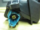
D4 Rear camera connector 142 viewsThis type is used on surround camera system.
|
|
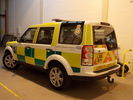
D4 Being Prepped for LAS26 viewsThis is a Disco 4 (unknown spec) being prepped up at my workplace for the LAS, having new comms kit put in and stuff. What you can't see from this angle is that the front grille and headlights have been taken out.
|
|
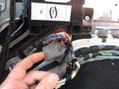
connector for timed climate reciever behind this foam 214 views
|
|
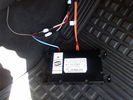
D4 Bluetooth AH42 10F845 AA module connected to 12VDC and MOST1210 viewsThis jpg shows the MOST bus connected to the AH42 10F845 AA module used in the D4 as well as +12VDC power from F58P connected. The power is split with a Y harness as the IHU (radio) for some reason required +12VDC power to the C2115-10 "mute" pin to keep the radio/CD audio from muting all the time.
With power on the pin, the radio audio does mute as it should when the cell phone rings and the hands free connects. The brown conductor feeds to C2115-10 and the blue to the module.
The module tucks up and hides behind the grey plastic section covering the forward portion of the passenger side tranny hump for left hand drive vehicles; for RHD, it would be located on the left side.
The pairing code is 2121 with this setup and not 1234 or 0000.
|
|
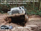
Whoever created this place, the Touareg can't drive through... Thanks man!60 views
|
|
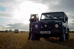
My Defender22 viewsDefender TD5 looking to keep it long term with a chassis replacement this year.but the quality / ride contrast between it and our Disco 3 is very apparent.
|
|
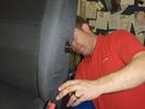
arm rest fit213 viewsthis is gary from trim-line... a job he knows to well as he is in landrover dealers most weeks..
|
|
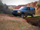
94 viewsWasn't sure I'd make this one. Had to break out the tape measure to make sure my tire would bridge the gap.
|
|

Defender in the Fog, another day on the job.459 viewsThis is another normal work day for a Defender - actually the jpg is from a Land Rover advertising shot, but it may just not be a set up one. I think it is an actual working Defender. Note the visible front tow hook and how the hi lift is just rope tied on; also the normal stock headlights and I guess dual spare tyres - just another day on the job.
|
|

Older Cell Phone handset holder operation and components849 viewsThis 8 page pdf explains the operation of the older Cell phone handset holder and shows the various components as related to the radio and phone buttons etc.
|
|

Cooling System - Description and Operation 4.0L and 4.4L petrol engines 5 pages1028 viewsThis is a 5 page pdf that provides some insight into how the coolant flows thru all the hoses. Of interest is the paragraph,(page 3/5), that attempts to explain how and why the thermostat is designed to open at different engine operating temperatures - in brief, the reason for the spaghetti tangle of small hoses on the top of the engine.
There is also reference to an engine oil cooler that I gather cools something I think related to a supercharger, if fitted.
|
|

415-07 Video Information723 viewsThis is a 5 page pdf that explains the operation of the overhead DVD setup as well as the TV option.
|
|

415-03 Audio System - Low and High Line Radios934 viewsThis 8 page pdf shows both the low and high line radios and their various components.
|
|

415-02 Antenna systems for AM/FM, Satellite, GPS and TV systems542 viewsThis is a 5 page pdf related to the antenna systems for the AM/FM radio, Satellite radio, the GPS/NAV and the optional TV.
|
|

419-08 Low and High line radio systems components and operation838 viewsThis 15 page pdf displays the radio components including pinouts for both the low and high line head units and the two Harman Kardon amplifiers including the Logic 7 amp. The steering wheel controls for both the radio and phone system are also outlined along with mention of the Sirius satellite radio feature.
|
|
Would you want this plate?63 views
|
|

Ford at Fen End, Start of UCR507 viewsToo thin this UCR for my big diso 3 though
|
|

Ford at Packington - West Mids469 viewsHard to belive this is right by the M42 and M6, and really close to the NEC
|
|
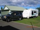
Another photo of the D3 & caravan outfit ... this time using the Mitchell Bros towbar and Hayman Reece WDH (May2008)126 views
|
|

NEW REG PLATES29 viewsHi Guys,
I would like to buy these plates. they dont seem to sell them in the shop. Does anyone have any problem with me using the disco3.co.uk on the bottom of the plates. id rather do this as i do not want to add any stickers to my car.
d
|
|

176 viewssealant used for sticking resistor to rear light and spot fixing the D4 front grill this stuff is superb but needs 24 hrs to cure
|
|
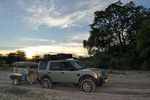
CALENDAR 201146 viewsThis photo was taken near Guma Lagoon camp in December 2009 while touring Botswana
|
|

DISCO3.CO.UK Calendar 2007144 viewsThis MS Excel workbook can be used to record the details of persons interested in the 2007 calendar.
|
|
Reckon a Disco3 could tackle this then?168 views
|
|
CALENDAR 2011402 viewsIn December 2009 we toured Botswana – first tour with the Disco, I had a yellow Defender previously. I rented a trailer, and the wheel bearing seized 1300km into the trip. This photo was taken while we waited for my friend to bring us a “fixed†hub. The elephant crossed the road less than 300 meters from us. Photo was taken 90Km from Nata
|
|

More snow, we got plenty this year748 views
|
|
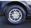
Please identify this wheel123 views
|
|
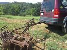
LR3 to plow your garden297 viewsI found this jpg where a current LR owner is using his LR3 for a similar purpose as the original Series units were designed to do - that is serve as a tractor for plowing a field or I suppose a garden.
In this case, I note the hitch is one of those that attach to the factory tow loop, (Rhino Hitch), rather than the factory product that inserts from the bottom and hangs down - (like a plow), but all the time. One of the other jpg's in this album shows the two factory variations plus a third jpg shows a closeup of the Rhino Hitch.
|
|
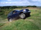
Dom, this is how its done!403 views
|
|
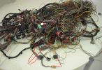
Donar Loom100 viewsThis ball of wires is from a LHD which has been opened and had all audio wires removed, however it is a gold mine for the bits i need. I have pointed out the connectors i know i need for starters near the bottom.
|
|
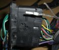
New Speaker Cables.111 viewsThis is the door connector, Main loom to Right, Door side to the left. to the top of the connectors you can see green and Green white wires which are the speaker ones. The door wiring is premium and has two pairs, the main loom was a 1 pair high line, so i am adding the pair you see (one already pinned up) to upgrade the loom to premium.
|
|

Driving 101 - a humourous PowerPoint Presentation file148 viewsItalian and humourous. Turn the sound on and have a quiet chuckle at the show. Only let the children watch if they are able to accept animated violence (some life forms were injured or killed in the making of this animation!!).
|
|

Drug dealers to the rescue264 viewsD3\'s will never live this one down!
|
|
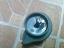
Remove this small metal rod, the hummer is a good solution189 views
|
|
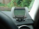
HARMAN KARDON DRIVE+PLAY219 viewsFOUND THIS A GOOD PLACE TO FIX THE SCREEN
|
|
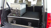
Ironman Drawers and Fridge Slide112 viewsI hate kitsets, over 100 bolts to assemble this unit and lost gallons of sweat, must have read the instructions a hundred times or more but final product does not look so bad. A few bolts hanging out the sides of both slide and drawers that may catch things so time will tell if I made the correct purchase.
Maybe one day I will make some side wings to cover the sides properly.
|
|
Some of the damage remaining from Hurricane Gonu - this was caused by flash flooding in the wadi86 views
|
|
A long, dusty and steep track - let my son drive up this one95 views
|
|
Perhaps this guy shoulf have had a bit of kip before tackling the hills113 views
|
|

Lead Car Entering the Finish116 views7 May 2007 - My D3 on duty as lead car in shinfield 10K road race. what a nightmare driving at low speed in the rain. Clock was mounted on standard crossbars. connection to additional batteries in boot cable thru side window. There is a small offroad section (actually an un-made road) Oaklands Road, Shinfield, Reading (suggest anyone test driving in the Reading area take this road)
|
|

Camp over roast lamb with onions - perrrrfect111 viewsThis was the best camp oven roast ever, fed six hungry blokes in the Oz outback on a winters Sunday night
|
|

v8161 viewsclose call this weekend
|
|
v8133 viewsClose call this weekend
|
|
What's this for then?387 views
|
|
No worms or mudfish were harmed in the making of this photo.....473 views
|
|

Dom, this is meant to be an open field we\'re in......220 views
|
|
63 viewsThe spot where the isolator box goes had this small white clip. It looked like it was meant to hold something....so I removed it.
|
|

62 viewsYou can see how the spot to mount the control box has the long flat section to the left - so I mounted the box upside down to allow the 2-sided tape to stick to this bit.
|
|
Simon hiding in the thistles342 views
|
|
Wind Deflector for Rack15 viewsRecognise this part? Its the lower front recovery point cover. Installed upside down to silence the wind "drone" on the roof rack - works a treat!
|
|
Disco 3 not available, so had to tolerate this awful £60k RRS instead :-o237 viewsOnly the half-day introduction course, but Geordie was an excellent tutor and we had an amazing time.
|
|
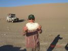
Gill Holgate with a huge shell. They were all over the place.163 viewsThis is somewhere on the beach on the way north to Tombua
|
|
Along the beach on the way to Tombua. The wreck in the background is "Consortium Alpha"160 viewsApparently this boat was wrecked on it's maiden voyage cos the prop got caught in the nets
|
|
a Defender 150. Apparently 5 were made. We saw this one at Land Rover in Windhoek, Namibia178 views
|
|
Real everyday use of 4*4: got a parking slot456 views No other car than 4*4 could have used this parking slot..
|
|
mud recovery220 viewsI think this is atacama in the poo. Heine is out of the picture to the extreme left. Note the white recovery rope stretching out of the frame
|
|
The "alternative route"160 viewsThis was the start of the rocky bit that cut out the snotty slopes. Wasn\'t the way to go unless you quit
|
|

78 viewsThis metal body seam gets touched by larger rear tyres. If you don\'t have rear AC, you can fold it out of the way. If you do, the two pipes mean you have to leave it alone.
|
|
This is the ground bolt on the chasis I used58 views
|
|
Twist the white plastic in either direction 45 degrees and pull - this is where the SC80 will go81 views
|
|
The Best Trailer Tent Ever74 viewsBought this trailer tent from Trek Overland, and think I should of kept it !!!
|
|
120 TONS115 viewsTHIS MACHINE IS AWESOME
|
|
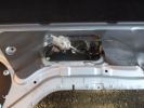
An alternative approach131 viewsDue to low temperature, and the size/mobility of my hands I decided that the easiest way to open the tail gate was to destroy the old Bowden cable and then pull centre core to release the tailgate - it worked, and doing this earlier would have saved a few cuts and grazes.
|
|
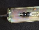
Shiny new cable114 viewsConnected to the solenoid, and looking quite smart. I hope this will last longer than the old one.
|
|
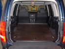
D3 Commercialisation622 viewsThis is the pic that was sent to me by the dealer to show what would be done to turn my SE into a van. (The car shown isnt mine)
|
|
My D3 before I bought it704 viewsThis pic was sent to me by the dealer - just to keep me awake at nights looking at my PC screen!!
|
|
Ah, no kids this time???69 views
|
|
399 views"Extended profile" height - this is as far as it got!
|
|
439 views"off-road" height - most wheel flex at this setting
|
|
The Road I came up.333 viewsThis is the road which caused my problem, drove up it, not realising there was a T junction which I had to turn right, turned, but could not get myself to get off the brakes and accellarate, so went straight on down a ditch!
|
|
Halogen infill alignment error152 viewsCar was 10-12 ft from wall when this was taken
|
|
V8 HSE Auto Reg 734 EAB366 viewsThis is the model D3 that everyone's got.
Ever noticed that although its a V8 auto, it's got a clutch pedal??
|
|
Internal water tank right side view161 viewsShows right front side of tank, with RH seat lifted. Note seat bolt is used to also hold the tank secure. This is a 5-seat D3, which has a cover over what is normally the 3rd row footrest. This is where the water tank is located.
|
|
Top view Left side of water tank128 viewsThis view shows the protective cap off, displaying tank vent point.
|
|
Saddleworth Moor in January60 viewsThis is where they are now looking, again...
|
|
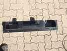
Top view of "Uncle Ray" discrete winch tray, after painting.106 viewsNote that towards the upper right there is a notch in the tray. This is needed for the specific winch's electric solenoid. The winch is a Mile Marker 12,000 lb hydraulic unit.
|
|
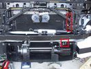
Installed winch with hydraulic hoses178 viewsThe hydraulic hoses are stiff, so I had to run them up the side of the radiator (can just see inside red boxes) to near the top of the radiator, then back down inside the engine compartment, then underneath the engine (behind the radiator) to the D4's power steering rack, where the hoses become metal. This hose routing may not be possible if the fuel-burning heater is in place (we don't have those in Aust and the space allowed room for my hands to bend and run the hoses without kinking).
|
|
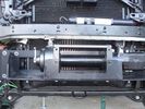
Close-up front view of partially-installed winch121 viewsNote that the sheet-metal flange just above the winch had to be notched to allow winch controller to be actuated. Also this same bracket had to be bent upwards to allow the winch hydraulic:electic solenoid to fit without rubbing. The nut on the upper-left bolt (the one with a very faint circle around it) stripped on re-installation, so the tray and winch pulling load is held only by the threads on 7 bolts....
|
|
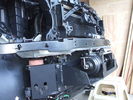
Front-right view (looking forward) of partially installed winch and mount124 viewsThe closest bracket, with three rubber grommets, is the air bag sensor. Before beginning any of this work, be sure to disconnect battery and discharge any remaining electrical power. I didn't want to accidently drop this assembly and cause the airbags to deploy.
|
|
Front bumper with cutout for winch rope entry117 viewsBumper was initially cut "too small" with a low speed hand-held jig saw. It was then progressively filed to about the right size. Finally a very sharp box cutter was used to provide a smooth edge to the cut. This cutout is hidden behind the licence plate.
|
|
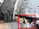
Further detail of attachment of the winch hoses to power steering system145 viewsThis is under the right (looking forward) lower plastic radiator cover.
|
|
it felt much steeper that this!!203 views
|
|
Ness's humps33 viewsI am pretty sure I split my mud flap here. still they are still attached to the car - this is one thing the wife did not spot ;-)
|
|
Mounting a non-LR fire extinguisher535 viewsShowing the plastic cover removed. I will make up a metal plate or bar so that the extinguisher frame can be mounted directly to this framework under the seat.
|
|
Ed saying "This is a winch"85 views
|
|

Range Rover Storm484 viewsWhy didnt they make this ??
|
|

Okakuejo (Etosha)118 viewsYou have to zoom in (couldn\'t post the 10Mb version) this is amazing! Looks like the queue to Noah\'s ark
|
|
142 viewsraised susspension - this i bought from the factory, so I assume you could order a trailer with this fitted. only necessary if you are fitting big tyres like I have. the axle is a standard alco axle which I ordered from alco with blank hubs. hubs were machined to accept LR studs. Wheel centres had to be slightly machined to fit over bearing caps
|
|
Fitted "echo" drawers in one of the front doors. an almost perfect fit, just a little sheetmetal work needed. the cho guys would probably vomit if they saw this107 views
|
|
121 viewsthis shows the fridge on the 2 x 180kg sliders. i had to slightly modify the door opening to fir the fridge hinges thru. I just gently bent it, and fitted additional seals, hence it can easily be returned to standard. having the fridge in the kitchen is a major bonus, plus the back door of the trailer is now used for easy access to the cavernous interior, whereas prior to this youhad only access thru the front doors, which are only 500mm wide
|
|
160 viewsCar balanced at this point on front nearside and rear offside wheels
|
|
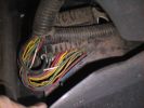
Left hand rear wheel arch, behind plastic shroud.720 viewsThis is the standard wiring.
|
|
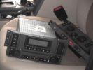
All the bits - don\'t let your wife see them like this!587 viewsHere\'s the stack all dumped on the passenger seat while i run the wires.
|
|

149 viewsThis is a JPEG Taken from the CAD drawing, it has nothing to do with NEXT BASE OR LAND ROVER,FORD TATA, its just a FUN Model and not to be used.......
|
|
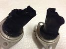
EGR Stub Pipes13 viewsThis what they looked like after 15K Km
Glad I fitted the Blanking kit
|
|

Whats this ??38 views
|
|

Pictorial instructions on EPB bedding in mode524 viewsDriving and reading LRs instructions is not easy - I tried this in graphic mode - MIGHT help
|
|

Fuel Purge Valve and other hoses.846 viewsThis 6 page pdf shows the Fuel Purge Valve and associated hoses and describes how it is supposed to work. There are lots of good drawings of the fuel system. It is more complicated than one might think.
|
|
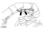
Exhaust Crossover Pipe157 viewsThis is the pipe that i am looking for.
|
|
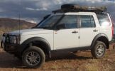
Widow maker - Alice Springs116 viewsHyper extended - Climbed the widow maker and the suspension found its way to this position by the top without any intervention.
|
|
Thread upload18 viewsThis is how you reach that TOP BOLT holding your air compressor bracket on. 10" extension, swivel, and 10mm socket taped so it won't fall off while your feeding it through the air compressor maze.
|
|
CALENDAR 2008709 viewsin the middle of nowhere (just before Perito Moreno, this time the city)
|
|
CALENDAR 2008 ENTRY641 viewsGoing where? En route the Perito Moreno (this time the city)
|
|
CALENDAR 2008 ENTRY633 viewsAnother ship wreck, this time in Chile
|
|
This is the baffle in the tailgate of a D3 sans subwoofer.221 views
|
|
Slimer demonstrating his prowess with his airbag!266 viewsneo was inspecting the underside at the time - not sure why?
Allegedly a 4 ton airbag was needed since the boot was full (and I can confirm this) of crates of Desperado
|
|
View from the Fairmile Carpark of 9 members cars198 viewsRange Rover Au Poivre had turned up by now - VA was having seat as well as steak sauce problems! I think we had 2 more turn up after this photo was taken
|
|
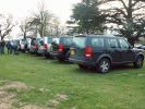
First seven arrivals at South East Pub Meet in Cobham232 viewsOnly neo\'s D2 was out of place at this point - more than made up for my the lovely burble of his V8
|
|
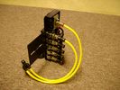
FASKIT on end view 864 viewsEnd and rear view of the FASKIT. Yellow lines are as shipped for hooking to the air supply; one line to valve/filler and other is to gauge. I will modify the arrangement to delete one of the yellow lines such that gauge line plugs into where the second yellow line is right now,(will be only one yellow tube), and then the air source line will plug into the port controlled by the valve, (hidden in this view but visible in other view). When white valve is in the ON position, gauge will read air source pressure, and be available to supply air to any of the selected four air springs. When valve is closed, the gauge will show individual air pressure in each of the air springs when a jumper is run between the gauge Schrader valve and the appropriate air spring Schrader valve.
|
|
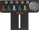
FASKIT air panel unmounted842 viewsThis is the manual air valve panel that is mounted in the "empty" space where the FBH normally resides. The gauge reads to a maximum of 25 Bar. The air tank relief valve is set just over 16.5 Bar (240 psig); the front air springs run maybe 9 Bar, (130 psig) and the rear, somewhat less, perhaps between 5 and 8 Bar. (70 to 115 psig). Max theoretical air spring pressure at full compression due to a big bump and full gross is approximately 27 Bar (390 psig).
|
|
My favourite 4wd , spent thousands of hours farming with this. Sold it in immaculate condition.129 viewsVery well engineered Tractor. 16 Fwd grs,4 speed P/Shift weighed 1800 lb alone (if I remember correctly), 4 equall sized clutch packs, alternates 2 lay shafts with clutch packs, dry sump. no master clutch or TQ/C,Cat 3306DTA. 1 of 12 in Australia.
|
|
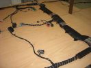
Finished seats area108 viewsThis is a shot of the loom when it was finished from the pass (RHD) door
Both of the seats wiring can be seen, i replaced the conduit on the bottom right and the Yaw rate sensr connector can also be seen in the middle.
|
|
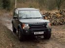
Some mud in the tyre treads at last!278 viewsThe D3 behaved herself beautifully on this little lane/track near me
|
|

Fluid, Filter/Pan Combo removal and install5979 viewsThese are the LR instructions re removal and install of the plastic pan/filter combo for the ZF 6HP26X transmission on the 4.4L petrol V8 LR3.
The instructions tend to ignore the reason you have to lift the right hand side of the engine about 40 mm. This is because of a frame cross member that interferes with dropping down of the plastic pan. The real problem is a vertical "oil filter spout" that rises out of the filter/pan combo up into the transmission. The spout is the suction pipe for filtered transmission oil back up into the tranny.
On the metal pan versions, the filter is separate from the pan, hence the filter remains with the tranny when the metal pan is dropped. The filter is then removed or installed independent of the metal pan, hence with the metal pan, there is no need to lift the engine.
If one is removing the plastic pan so as to install the metal pan, then some do not lift the engine but just drop the plastic pan enough to gain access to saw off the vertical plastic spout - it is a one time procedure.
Be aware however that the metal pan uses a flat gasket and the plastic pan uses a O ring like perimeter gasket that sits in a half round groove in the tranny casing. Also the metal pan uses 21 shorter torx M6x22.5 metric cap screws for the perimeter bolts. The plastic pan uses longer M6x28.5 torx metric cap screws.
|
|
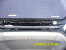
FM/AM/TCM Location56 viewsThis is the location and connections for the FM/AM and TCM
|
|

Ford News Cover Story May 2006218 viewsFord News is a monthly publication (aka propaganda!) magazine, given to all Ford workers. This months issue has a lead article about the TDV8. Thought it might be of interest.
|
|

Exploded Parts view calling up 6R60/80 and 6HP26/28 variations3113 viewsThis single page jpg exploded parts view indicates some commonality between the Ford and ZF versions of the early and later six speed units. Technically this sheet is for the RWD units as there are variations between plain RWD units, 4WD, and AWD. The transmission in the LR3 is called by ZF to be a 6HP26X and by LR in some publications, the 6HP26
|
|
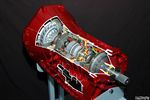
Ford 6R60 six speed cutaway showing torque converter.2198 viewsThis is a cutaway of the Ford 6R60 six speed which is a Ford license built version similar to our ZF 6HP26 six speed speced on early 3's.
The newer 3's and 4's have the ZF 6HP28. The Ford version is called the 6R80 and variations of it are used on the Raptor. As such, the Raptor metal pan can be installed on the 3's tranny but the deeper Ford Raptor pan does not have a drain plug.
|
|

Ford Sounder 4L1Z-15K864 A that I installed.12 viewsThis is the Ford sounder, part number 4L1Z-15K864 that I purchased and installed in lieu of the official Land Rover sounder. Note the part number is what is printed on the box (and also my invoice) but the part number on the sounder body is a bit different. I think a new box/invoice related part number is created each time the price of a part is changed. Regardless the Ford sounder was about half the cost of the Land Rover part and sounds the same as the removed factory buzzer.
|
|
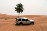
Palmeira34 viewsIt was dificult to clim this dune ..
|
|
Calendar 2010291 viewsLand Rover Discovery 3 in Southern Namibia. A private road constructed by my employer to service cellular base stations. The location is Frederickshoop in the South of the country. 500m drops made this terrifying.
|
|

Land Rover TSB LTB00245 install instructions1939 viewsThis is the Land Rover Technical Service Bulletin showing how to install the new breather cap. The instructions are a bit vague re cutting the existing air vent tubing on a 45 degree angle with the cut facing to the rear.
|
|

Breather Hose exploded view.1231 viewsThis pdf shows the exploded view of the breather hose from the front differential to the engine compartment. The breather hose part number is TAP500081 and is identified as 4A058 in the drawing.
|
|

3 viewsLove this place
|
|
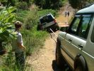
Insane117 viewsThis was the predicament that resulted in the panic recovery attempt.
|
|
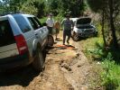
Winch/snatch block113 viewsThis picture shows the winch in position.
|
|

Series LR at Oil Sands Plant in Northern Canada circa 1968747 viewsThis is an end of shift picture taken about 1968 at the Great Canadian Oil Sands (GCOS) plant while under construction in the Ft McMurray area of Northern Canada.
I was surprised to see the yellow coloured Series single cab hardtop pickup parked in about the centre of the picture. I would say it is one of the few on site as most vehicles were Chevrolet's, (as are the other three trucks elsewhere in the view). The yellow painted vehicles including the Land Rover are most likely Bechtel owned - not leased - yes, that long ago now.
|
|
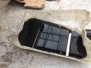
39 viewsmanual gearbox oil at 72k the transfer box oil look the same as this
|
|

Fix stiff gear selector or jumping out of drive into neutral32 viewsThis is a document culled from a topic about a simple fix to teh gearbox selector lever that fixes a problem with jumping out of drive into neutral.
I made the document to give to my local independent and thought it might be useful for others.
Thanks to disco_mikey, EdF and Robbie from the original post whose information and photos made this possible (I take no credit for anything here apart from errors).
|
|

Fix stiff gear selector or jumping out of drive into neutral17 viewsUpdated 19 Dec 2012
This is a document culled from a topic about a simple fix to the gearbox selector lever that fixes a problem with jumping out of drive into neutral.
I made the document to give to my local independent and thought it might be useful for others.
Thanks to disco_mikey, EdF and Robbie from the original post whose information and photos made this possible (I take no credit for anything here apart from errors).
Updated after I did this fix on my own car.
|
|

Click this, I can't stop watching it, it's epic!!54 views
|
|

Gore Tex data sheet on Breather Cap.784 viewsThis is a Gore data sheet on the air vent material that is within the breather cap. The filter material has both hydrophobic and oleophobic properties. That means it keeps water out and the differential oil in.
Also the membrane material is air permeable; that means air pressure is equalized between the interior of the differential and outside air. This is important when the 3 is flying at altitude in the back of a Hercules with the rear door open - that is the rear hatch of the Herc.
|
|

Snake Lake136 viewsNo problem getting through this wash on our 2nd try. Tried to straddle rocks on first, that was a bad idea.
|
|
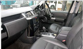
New Dash59 viewsIs this black plastic stuck on or is it actually part of the dash console cover?
|
|
Gulp! - All this has got to fit in!159 views
|
|
94 viewsI hiked up to a cave, this is from about halfway up. Very steep climb.
|
|

High Beams Main Beams Wiring Diagram76 viewsThis is the wire colors and connections for Dipped, Main, and Side Marker lights
|
|
This baby is awesome!130 views
|
|

Sheepy Parva Forf27 viewsWhen the water is to this height its far too deep, even with a RAI
|
|

can you identify this bracket?25 views
|
|
Rhino Tow Loop Hitch269 viewsThis is a receiver end view of the Rhino Hitch that ties to the factory tow loop. In addition to improved strength, it does not reduce ground clearance as does the factory style when installed.
Land Rover in early advertising videos when the 3 first came out showed the D3 hanging from a crane via the frame. The intent was to show how strong the frame is and by inference, the rear tow loop, specifically noted as being good for 6 tonne. The video ends before anything dropped or was lowered back to the ground, so one of course does not know for certain. The Rhino Hitch design however picks up on the apparent evidence of strength and certainly the additional clearance.
|
|

Can you belive this !459 views
|
|

You\'ve seen this in a movie, but which one ?495 views
|
|

Well, would you swin in this. The pic doesn't show it, but this Loch looks a tad on the iffy side, and its drinking water ????157 views
|
|
The views don\'t get any better than this !!!167 views
|
|

The views don\'t get any better than this !!!164 views
|
|

The views don\'t get any better than this !!!152 views
|
|
The views don\'t get any better than this !!!170 views
|
|

The views don\'t get any better than this !!!168 views
|
|
Skye Bridge . My Sat Nav thinks this is a toll bridge ???183 views
|
|
At the 1303 mile mark, Av MPG was 30.4 !!!!!!!!!!!!! With all teh start / stop, and general moochign about, this was quite good !307 views
|
|

12 views
|
|

IIDTool EAS Calibration Excel87 viewsThis is the spreadsheet I made using Numbers 3.1 on a Mac, exported as an Excel file.
I haven't tried it on anything other than Numbers though.
|
|

Calibration Spreadsheet for Mac Numbers48 viewsThis is the spreadsheet I made using Numbers 3.1 on a Mac
|
|

Pre Suspension Calibration59 viewsA spreadsheet I made showing results of suspension calibration using Gap Diagnostics IIDTool.
This is the pre-existing values
|
|

Underside of the ciruit board128 viewsThis looks more of a mess than needed to be. The Maplins guy tried to be helpful when I bought the relays, he wrote down the switching COM/NO/NC, it was actually NC/COM/NO. Some scratching of head when it didn't work then worked out what happened when I looked on the manufacturers website at the data sheet...lesson of the day check the data sheet!
|
|

Close up - key removed17 viewsIn the center is the added switch with removable key.
Here the key is removed.
This is to add an additional 'protection' from discharging the auxiliary battery in case other people are working on the car and accidentally switches on any electrical bit :)
|
|
12V outlets for the 2nd row13 viewsI used a part of the old front (which was broke) to cut out a 'mount' for three 12V outlets for the second row.
The outer outlets are switched on whenever the ignition is on as I used the connector that originally was out there.
The middle outlet is connected to the auxiliary battery and is switched on/off through a rocker switch in the central console. (other picture)
This middle one is going to be used for our small fridge that usually resides just there when we're on holiday.
|
|
One of the multimedia headrests14 viewsI used to have seperate touchscreens mounted on the headrests.
I now went to the xtrons 9" headrests which gives the children the possibility to
- view whatever movie they want to
- listen to whatever music they want to
- play whatever 32native game they want to (although I'm not quite happy with those)
and they can do this no matter what the other one is doing :)
|
|

President Johnson II in its current position18 viewsThis CB was installed some years ago and still is at the same location.
However, I'm planning to move it to the head unit area.
As such, I'm looking around to replace my low end head unit with a single DIN radio and the CB on top of it.
|
|
38 viewsWhen adding two single DIN supports together, you get quite a gap at the front.
This gap was way too much in my case, as it turned out that both supports started to bend when putting them both in the facia. Not that good, so I decided to cut off the upper part of the lower DIN support.
|
|

An extra twist on running lights30 viewsAdded those nice 120mm LED rings on the covers of the roofrack lights and have them connected to my roofrack lights switch, as I wanted to control the LED manually as well (I don't believe this is 'road-legal', hence why I opted for the manual solution).
|
|
yingyang the origin28 viewsyes this is where it all began
|
|

a poo with a view26 viewsI popped to a loo this was the view
|
|

dam28 viewsthis provides all the drinking water for the city Chengdu
|
|
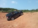
this is where i scrape my bum30 views
|
|
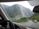
a landslide from earthquake32 viewsstill evidence of the barrier lakes formed from this
|
|

collecting wood30 viewslocals cant cut down trees (finally linked to landslides) so the wade into this fast flowwing river to collect drift wood. water is very fast flowing and muddy and has logs floating down
|
|
don\'t fancy this chasing me down....................108 views
|
|
|
|