| Search results - "switch" |
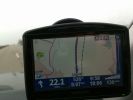
How fast?231 viewsI was driving along the Autobahn, glanced down at the speedo which was showing 140 mph, the Tomtom was telling the truth at 132 mph, but by the time I had switched the phone to camera I had dropped 2 mph, didnt try and do it again as there was no need.
|
|

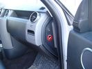
key out security switch 147 views
|
|
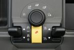
Terrain Response Switchgear2378 views
|
|
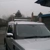
SR switched off87 viewsSR40 lightbar
|
|
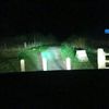
all lights switched on 79 viewsthis is the Bixenon with LR HID converted spotlights and the rigid SR40 lightbar switched on
|
|
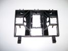
137 viewsThe bracket with sections removed for the switches
|
|
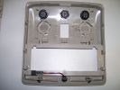
160 viewsRoof panel with the new switches
|
|
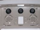
197 viewsSwitches installed in the roof panel
|
|
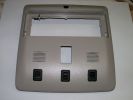
177 viewsSwitches in the roof panel
|
|
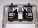
160 viewsThe switches fit into the new holes in the bracket
|
|
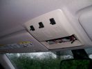
239 viewsPreview of the panel with the switches
|
|
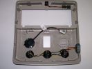
206 viewsRoof panel with wired switches and PTI microphone
|
|
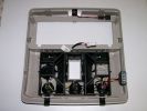
206 viewsRoof panel with switches, PTI microphone and bracket
|
|
392 views
|
|
410 views
|
|
391 views
|
|
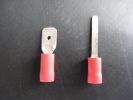
use right hand crimp301 views
|
|
319 views
|
|
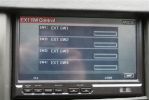
17298 viewsYou can add relay switches to the controller to turn on & off from the touch screen...pretty cool.
|
|
18 Dash Loom47 views
|
|
Suspension dragster mode442 viewsAfter I succesfully changed my wintertyres to summertyres, I found out that the front suspension was on access level and rear at off-road. Situation cleared after I switched engine on.
|
|

10 views
|
|
Socket for control lead and switch for radio-remote moved from solenoid pack to bumper1037 views
|
|

Thread upload13 viewsImage uploaded in thread 151728
|
|
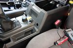
76 viewsDrilled hole for switch
|
|
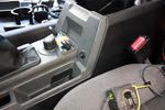
76 viewsSwitch in place
|
|
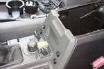
99 viewsAll 4 switches in place.
Driver's side switches are:
. Parking sensors master switch
. Reverse camera off/on/reverse-tiggered
Passenger side switches are:
. CarPC off/on/ignition-triggered
. 12V Regulator off/on/ignition-triggered
|
|
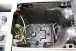
73 viewsStarting the switch wiring
|
|
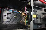
70 viewsAll switch wiring neatly routed to exit hole
|
|

265 viewsSmooth leather steering wheel with cruise and Radio switches
|
|

Opaque switch cover119 viewsKR switch on:off:on used for front and rear spots - but LEDs not visible with coloured switch cover!
(Located in sunroof switch position)
|
|

KR switch with drilled holes118 viewsResults of drilling holes in opaque switch to see LEDs. Simple ideas can be the best - thanks Dad!
|
|

KR switch cover drilled117 viewsNow I can see the LEDs underneath!
|
|
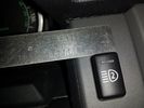
Light Kit switch2068 views
|
|
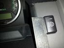
Light Kit switch1140 views
|
|
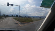
switch16 viewsthe point where you switch from right to left side road.
Laos is drive on right..Thailand left
|
|
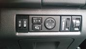
Switch Bezel25 views
|
|

window switch trim47 views
|
|

Rear heated seat loom and switches4 views
|
|

Seat Switches8 views
|
|

Anti Lock and Traction Control description and operation.1986 viewsNote on page 6 of this 17 page pdf the significance of the Steering Angle sensor mounted on the steering wheel shaft. The paragraph regarding the plausibility check as related to the brake pedal being not depressed is why the clean operation of the second set of contacts on the brake switch matters so much.
|
|
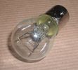
Land Rover Stop Tail Light dual filament bulb nominal 12 volt 21 / 5 watt filaments1427 viewsThis is the Land Rover part number 264590 dual filament bulb, (P21/5), that inserts into the upper two tail lamp receptacles. In the upper one, both filaments function, in the lower one, only the 5 watt tail light filament functions.
I regard it as not a good practice to routinely switch bulbs when the tail light filament, (5 watt), burns out on the lower bulb. The broken filament can jiggle over onto the brake light filament, (21 watt), and short the circuit to ground or something else not predicable.
There are also arguments to say that quality control is better on the Land Rover marketed bulbs than say far east sourced bulbs. Filament construction, and hence resistance can vary and mislead the current sensing circuits monitoring the signal light systems. Also when the bulbs are properly installed, all filaments should be standing vertically and not at any slope.
These are the sort of obscure circumstances that can lead to false trouble messages on the display, dropping to the stops, and subsequent concerns - all over a tail/signal light bulb.
For example, the filament life of both the tail light and the brake light filaments in the P21/5 bulb is significantly less than the USA common 1157 dual filament bulb, (1000/250 vs 5000/1200 hours); brightness in the P21/5 is a bit more, (3cp/35cp vs 3cp/32cp where cp is candle power), but current consumption is oddly less, (0.44a/1.86a vs 0.59a/2.10a where a is amps). It is the quest for efficiency vs maintenance trade off.
|
|

Switch18 views
|
|

Thread upload5 viewsImage uploaded in thread 180980
|
|

9 views
|
|
Switch Bezel18 views
|
|

Alarm System description and Operation1052 viewsThis 9 page pdf explains in detail how the anti-thief, (alarm), system is supposed to operate. The system uses the door ajar switches to provide alarm system signals; as such there are few separate contacts related to the alarm system only.
Page 6 of 9 is of particular interest as it describes the trigger log that is accessible with the dealer T4.
|
|
Thread upload13 viewsImage uploaded in thread 183983
|
|

Rack76 views
|
|

Add A Circuit Littelfuse Data sheet2278 viewsThe switch connects to what Littelfuse brand calls an Add-A-Circuit model FMH200BP which is an adapter that plugs in place of a Mini fuse and then has space for two Mini fuses, (original and a second one). In this install, only the original 5 amp fuse was used - adapter was so as to route power from fuse box thru fuse, then rocker switch, and then back to fuse box.
Before you install the Add A Circuit for this application, take an ohm meter and trace out the circuit path of the four slots that fuses could insert into. The path is more complicated than one might first think. As such, the orientation of the fuse holder in the socket matters for this application - that is for a circuit diverter, rather than accessory adder.
|
|

Thread upload12 viewsImage uploaded in thread 168641
|
|

Thread upload11 viewsImage uploaded in thread 168641
|
|
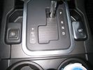
D4 Auxiliary Light Switch351 views
|
|

26 views
|
|
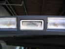
upper tailgate switch without rubber120 views
|
|
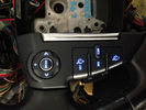
Blue switches53 views
|
|
Thread upload16 viewsImage uploaded in thread 124306
|
|
Thread upload7 viewsImage uploaded in thread 139598
|
|
Thread upload10 viewsImage uploaded in new thread
|
|
48 views
|
|
Thread upload0 viewsImage uploaded in thread 195722
|
|
Thread upload0 viewsImage uploaded in thread 195722
|
|

Thread upload21 viewsImage uploaded in thread 152975
|
|

Thread upload42 viewsImage uploaded in thread 137607
|
|

Black Deposits to interior of Brake Light Switch2860 viewsThere are two contacts, one on each side of the vertical plunger under the copper metal. The set of normally open contacts on the left side that carries the power for the brake light filaments, (15 amp fuse F15P), is apparently not heavy enough as the contacts deteriorate and generate the black residue.
The set of normally closed contacts on the other side appear to be sized OK. There is not as much current, (5 amp fuse F66P), flowing thru the contacts to the ABS module, however the contacts are likely adversely affected by the black residue produced by the other deteriorating set of contacts.
One presumes/hopes that the newer replacement switch now has contacts heavy enough to carry the brake light power. It would be ideal if the ABS set of contacts were sealed from the brake light contacts to prevent contamination of the normally closed set of contacts.
|
|

Brake Light Switch, Find, Remove, and Install Instructions 7851 viewsThis is a two page doc outlining where to find the brake light switch, how to remove it, and then install the new one.
Note, do not move the brake pedal when removing or installing the switch. Let the brake pedal hang where it wants to. The switch design is actually cunning, and as such is supposed to make the removal and install fool proof. Hence if you think too much about it, you can wreck the new switch.
If you want to inspect the interior of the switch, wait until you have removed the old switch. You can then just unsnap the blue from the white to get it apart. Inside, the switch is quite simple, (no circuit boards), but it will probably show black dust from failing contacts.
I think the reason the switch fails is that the Normally Open, (NO), contacts of the brake light contacts were made too light to carry the current load for make and break of the tail light filaments. I also think the black dust created then fouls the Normally Closed, (NC), second set of contacts for the ABS circuit. As such, the Normally Closed contacts become intermittent in operation and display as a fluctuating open and closed circuit condition to the ABS system when the ABS should be seeing a steady closed circuit. Hopefully the replacement switch contacts are more robust and may be as I recently replaced my switch again just as a matter of maintenance. While in a redesign, ideally the NC contacts should be sealed or at least separated from the NO contacts, when I inspected the removed switch, this time there was no black dust present.
Probably the removed switch will have a Land Rover oval logo moulded into it, the new one, FOMOCO.
|
|
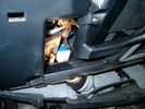
Brake Switch Visible thru Opening4973 viewsThe blue and white bit is the switch; the sort of gold appearing box,(it is really black), you will not see in your 3 as it is a Smooth Talker brand amplifier for my Blackberry phone antenna. This install is detailed in the SmoothTalker phone antenna section of my gallery.
One way to remove and install the switch is to lower the "horizontal" panel above the brake pedal as shown where the flashlight head is located. To actually remove the switch, you slide your hand thru the gap and rotate the switch clockwise 1/4 turn while watching thru the rectangular opening. Installation of the new switch is the reverse of above - 1/4 turn counterclockwise.
Before you remove the switch, note its orientation - horizontal with electrical wires to the left. That is the way it should look after replacement as well.
The second time I replaced the switch, I did it all thru the rectangular opening and did not remove the horizontal panel - that is experience helping out.
The knee kick you have to remove regardless. It is sort of hinged at the bottom so you just pull at the top and sort of rotate the knee panel and then pull upwards for two plastic "fingers" to clear the slots they reside in.
|
|
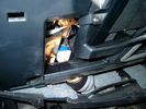
Smooth Talker Amplifier Box mounted below near steering column.179 viewsThe gold look box due to the lighting, (actually black), is the antenna amplifier located near the steering column. It can be put anyway but this seemed an OK location as I ran the antenna connector cable rearward from here to the back corner of the 3 and then up to the underside of the roof glass at the rear. The blue/white thing is the brake light switch that often must be replaced. See the Brake Light Switch file within this Gallery regarding the switch replacement.
|
|

Black Deposits on Brake Light Switch Plunger2757 viewsThis jpg I got off another forum and is typical of what one will see when one opens up the removed brake light switch. The black powder is residue from arcing of one of the pair of contacts within.
Hopefully the newer switches with the FOMOCO logo moulded into the plastic are improved from the Land Rover logo marked early units, however I doubt it.
The Ford part number is SW-6572 and/or 7E5Z-13480-A as used on the 2006 to 2009 Ford Fusion's and Mercury Milan's; the Land Rover part number is XKB500110. Cost of switch could be about twenty five dollars. A previous LR part number for the switch was XKB500030, so hopefully the newer LR part number, XKB500110, reflects some improvement in reliability.
It is possible that the new switches are better as I installed a replacement 72,000 km, (45,000 miles) later, at 195,000 km (121,000 miles). When I took the removed switch apart to inspect, it was clean inside. There was no black dust - the switch looked like new, hence they must be improved now.
|
|
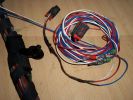
Burnt Bit97 viewsThis bit of wiring going to the connector was so close to bulkhead it got a bit burnt, Its for the clutch switch on a manual used for EPB, It will be replaced connector to pin with the wiring shown.
|
|

Central Door Locking Operation Description1458 viewsThis 17 page pdf explains how the door locks are supposed to operate. Note that on page 9/17, the explanation of the operation of the hood ajar switch is wrong. It operates similar to the door and tailgate ajar switches; that is when a "door" is closed, the switch is closed to maintain a ground back to the CJB. Opening the hood, door, or tailgate removes the ground breaking the circuit and hence allows for an alarm condition.
|
|
Thread upload6 viewsImage uploaded in thread 175355
|
|
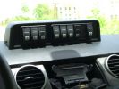
Mud UK switch binnacle453 viewsToo many switches for the roof mounted console, so this binnacle from Mud UK (desigend for the Defender) is an almost perfect match for the leather finished dash in the LR3. Switches, connectors etc bought from them too. From L - R switch functions are:
LH side mounted rack lamps
Driving lamps rack mounted
Spot lamps rack mounted
Bumper mounted driving lamps
RH side mounted rack lamps
Warn winch isolator
Rear mounted rack lamps (reversing)
Telescopic work lamp (fitted behind RH spare wheel)
|
|
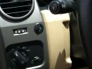
Long Ranger auxilairy fuel tank pump switch and tank gauge308 viewsFitted to the right of the air vent thumbwheel, the neat combination switch and gauge take sup no room at all. Switch locks on or off, but no pump running warning lamp! Contents of the tank are indicated by 5 LEDS, 4 green and 1 red for full, 3/4, 1/2, 1/4 and empty. Pump transfer rate of just 2 litres p/min is disappointing. I transfer on the move when main tank is at 1/4.
|
|
Thread upload5 viewsImage uploaded in thread 188726
|
|
cruise control switch135 views
|
|
cruise control switch132 views
|
|
Thread upload10 viewsImage uploaded in new thread
|
|

ARB air compressor switch, gauge, outlet.313 views
|
|

138 views
|
|

D3_Brake_Switch25 views
|
|
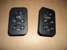
Audio Switches34 views
|
|

140 viewsHeight controller switch on High (+50mm) setting in my D4
|
|

146 viewsHeight controller switch on Low (-20mm) setting in my D4
|
|

137 viewsHeight controller switch on Medium (+30mm) setting in my D4
|
|
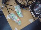
Prototype wheel switch test38 views
|
|
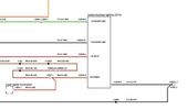
D4 Aux Lights Switch Wiring Diag80 views
|
|
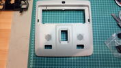
Roof console with cutout for switch(es)60 views
|
|
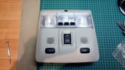
Roof console with mounted switches148 viewsOne switch is for switching the R-750 spot lamps, the other is for additional external lighting using a second Relay kit provided by OEM Plus.
|
|

Thread upload17 viewsImage uploaded in thread 136537
|
|
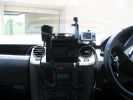
369 viewsHome made console, GPS in clip off mount, 29Mg radio,dual battery moniter,long rang tank gauge & elecric switches.A clip out removable console with no screws.PS also a camera mount.
|
|
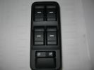
window switch 2402 views
|
|
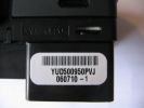
window switch part number364 views
|
|
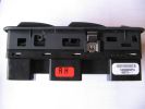
window switch371 views
|
|
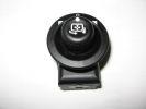
mirror switch457 views
|
|
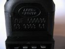
mirror switch part number504 views
|
|
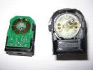
mirror switch apart 2415 views
|
|
mirror switch apart389 views
|
|
Window Switch Covers83 views
|
|
44 views
|
|
Steering Switches JPG53 views
|
|

Steering Switches51 views
|
|
Thread upload21 viewsImage uploaded in thread 157544
|
|

Thread upload11 viewsImage uploaded in thread 115638
|
|
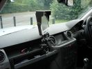
Screen profile437 viewsNote that the passnger airbag is switched off when the screen is fitted - no problems to date with solar gain on the rear of the screen
|
|
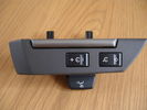
LH Switch36 views
|
|
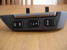
RH Switch33 views
|
|
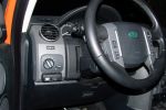
Switch lights428 views
|
|
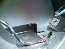
Overview423 viewsSharp edge of frame is dead centre of image.
Eroded "switched live" feed is blue wire high on the right
|
|
Thread upload4 viewsImage uploaded in thread 149835
|
|

EZY Switch iPhone utility screenshot12 views
|
|
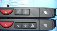
Forward Alert switch63 views
|
|
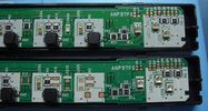
Forward Alert switch internals45 views
|
|
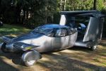
Is it a Car? is it a Plane?108 viewsA new car could prove the perfect way to beat rush hour traffic - because at the flick of a switch it turns into a plane. The AirCar will be able to cruise at speeds of 200mph - at a staggering 25,000 ft. It will cost around £250,000 and should be on sale by 2010
|
|

Front_Seat_Control_Switch164 views
|
|

Thread upload14 viewsImage uploaded in thread 173582
|
|
Thread upload4 viewsImage uploaded in new thread
|
|
Thread upload0 viewsImage uploaded in new thread
|
|

Thread upload2 viewsImage uploaded in new thread
|
|

Thread upload2 viewsImage uploaded in thread 89442
|
|
Thread upload15 viewsImage uploaded in thread 127724
|
|

Thread upload12 viewsImage uploaded in thread 127724
|
|
Thread upload9 viewsImage uploaded in new thread
|
|
66 views
|
|

56 views
|
|
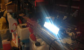
E Series lightbar switched on72 views
|
|
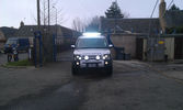
D3 with everything switched on118 views
|
|

Underside of the ciruit board128 viewsThis looks more of a mess than needed to be. The Maplins guy tried to be helpful when I bought the relays, he wrote down the switching COM/NO/NC, it was actually NC/COM/NO. Some scratching of head when it didn't work then worked out what happened when I looked on the manufacturers website at the data sheet...lesson of the day check the data sheet!
|
|
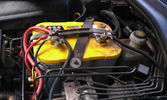
The auxiliary battery21 viewsThe auxiliary battery in the bay.
As the wiring diagram I made shows, there's a wire leading to the fuse box in the rear. (is going through the key-switch)
The second one is going to the fog lights. The smaller cables which should be connected to the head-lights, are connected to the battery.
The third one is going to the compressor (via a switch) (sits before the key-switch)
A fourth one is going to the CB and battery check display (sits before the key-switch)
|
|

Close up - key removed17 viewsIn the center is the added switch with removable key.
Here the key is removed.
This is to add an additional 'protection' from discharging the auxiliary battery in case other people are working on the car and accidentally switches on any electrical bit :)
|
|

Close up - key in place16 viewsThe key placed and turned in order to turn the switch on.
Everything connected to the fuse box in the rear and the fog lights on the roofrack will work now.
|
|

New switch18 viewsNearly 5 years ago, I fiddled with some push-buttons, until one day I came across those marine Contura rocker switches :)
The remote control is the switch just behind the EPB.
|
|

The on/off switch for the middle outlet10 viewsThe left switch without the label is the one that now controls the middle 12V outlet on the second row. It used to be the power on/off of the car-computer.
|
|
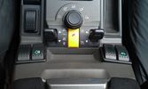
The on/off switch for the compressor12 viewsThe rocker switch for the compressor is the outer right one with the label of the .. euh, compressor :D
|
|
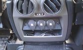
12V outlets for the 2nd row13 viewsI used a part of the old front (which was broke) to cut out a 'mount' for three 12V outlets for the second row.
The outer outlets are switched on whenever the ignition is on as I used the connector that originally was out there.
The middle outlet is connected to the auxiliary battery and is switched on/off through a rocker switch in the central console. (other picture)
This middle one is going to be used for our small fridge that usually resides just there when we're on holiday.
|
|
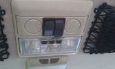
The on/off switches of the multimedia headrests17 viewsThese switches were installed to power on/off the previously installed gamecube and the screens attached to it.
When I removed the gamecube and lately the screens as well, I was clever enough (surprised as well) to leave the switches and all the wiring that I had running around.
They came in handy when I installed the multimedia headrests and are now adding an extra power on/off control of the screens.
|
|
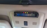
Battery check display15 viewsI mounted a digital battery display in order to see the voltage on the auxiliary battery.
There's also a thermometer which gives the inner and outer (via a side switch) values.
The display is switched on/off via another rocker switch.
|
|
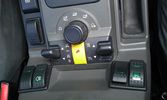
The on/off switch for the battery display22 viewsThe right inner switch 'powers' the auxiliary battery display. I might use that one to power on/off the driving camera (which will be arriving soon) as well. Although I'm not sure yet.
|
|
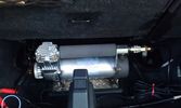
The compressor in the booth16 viewsThe rear of the second row seats are visible and the space behind was big enough to put the compressor.
The compressor is powered from the rocker switch in the front.
|
|

An extra twist on running lights30 viewsAdded those nice 120mm LED rings on the covers of the roofrack lights and have them connected to my roofrack lights switch, as I wanted to control the LED manually as well (I don't believe this is 'road-legal', hence why I opted for the manual solution).
|
|
light switch, no front fogs18 views
|
|
switch column 328 views
|
|
switch column 432 views
|
|

switch column 227 views
|
|

switch column 125 views
|
|

Network single switch30 views
|
|
Netbook external switch closed69 views
|
|
Netbook external switch open74 views
|
|
942 viewsFitting Nokia 810 car kit and fog light switch
|
|
1628 viewsSome of the heavy wiring from the switch pack to the winch motor done.
|
|

Showing compressor, tank, pressure switch569 views
|
|
On switch and pressure guage554 views
|
|
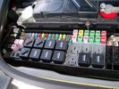
Picture of the engine compartment fuse panel5779 viewsEngine compartment fuse panel located near the battery. This is where F3E, (5 amp), F26E, (20 amp), Fuseable link 10E, (60 amp) and Relay 7E, the now upgraded 70 amp air compressor motor relay, part number YWB500220, (E is for Engine compartment fuse box), are all located. Fuse F35P, (5 amp), is inside the Passenger compartment behind the lower glove box door.
To keep the suspension from going down to the stops when driving, (or parked), it appears that it is only really necessary to remove F26E to depower the exhaust valve and generally keep all the valve block solenoid valves in a closed position trapping whatever air is within the air springs. F3E gets its power thru F26E, so when F26E is removed, the F3E circuit is automatically de-powered. F35P is more interesting in that battery power goes thru the ignition switch and F35P and then into the air suspension control unit. Apparently however, if F26E is removed, removing the F35P is not needed even when the engine is running.
With all fuses still in, if you have a problem, in practice, ideally, the compressor still works and will raise the 3 to an appropriate height. If so, one can then shut the engine off and allow the computers to go to sleep and then you remove the fuse(s). In actual practice, it seems that one need only pull the F26E fuse and can do so with the engine running. All the same, one might consider that the 3 is first a mobile computer, and secondly a 4x4. Computers prefer to go to sleep before the plug is pulled on them, however given that F26E circuit is always alive, then the computer never sleeps. With the fuse(s) pulled, and if you are still up, you can now be a 4x4 instead of a low rider. The whole purpose of the fuse pulling exercise is to depower the one and only system exhaust valve that is physically located within the compressor unit, (to keep it from opening), and secondarily to keep closed the four air spring solenoids within the block valves. This also shuts the air compressor down and stops the air compressor from making air even if the compressor is still good. That is why you initially need the fuse(s) in to allow the compressor to make air if it can.
|
|

Switch is blue colour thing thru the rectangular opening.3177 viewsThe blue coloured plastic bit thru the rectangular opening is the brake light switch. The fist time, I found it easier remove the switch by dropping the horizontal plastic panel, (two screws), and then slipping my hand in and rotating the switch clockwise 1/4 turn. The second time, I was able to remove the switch thru the rectangular opening and did not need to remove the horizontal lower panel. Obviously, I had to remove the sloping knee pad panel, (note sort of hinged at the bottom so pull back from the top.)
Regardless, do not touch the brake pedal - just let it sit where it wants to. One has to first remove the angled knee pad panel that sits under the steering wheel. It can be pulled from the top corner at the door side. Pulling releases a pair of those U shaped metal clips that LR loves so dearly. You have to pull quite hard. The bottom is held by a couple of plastic fingers in a couple of slots so you pull at the top till the two clips release and then rotate the panel and pull upwards a bit.
To remove the switch, you rotate it clockwise and pull outwards. Rotating the switch clockwise automatically retracts the plunger back into the switch body away from the brake pedal arm.
Similarly when you install the new switch, the required 1/4 turn anti clockwise rotation action releases the plunger so it lays up against the brake pedal arm and at the same time, secures the switch in place.
To remove the electrical wires, the switch will drop below the horizontal pad and hang from the wires so unclipping the electrical connector plug is fairly easy to do.
|
|
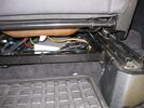
AV switch mounted beneath the front passenger seat62 views
|
|

533 viewsAdded an extra switch to the + leading to my PC and to the MP3 changer. As such I can cut off the power to both systems when needed. Learned that one after 2 days constantly working in the car, lighting the whole thing up during 2 days and noticed I couldn't start anymore :D. Saved by my wife's Freelander next to me :)
Also to be seen is the remote controller of the MP3-changer.
|
|

418 viewsSwitch in up position, bright controller. I love the blue. A pitty all the other displays in the car are in green.
|
|

Switch centralina sospensioni 136 viewsImmagine del posizionamento occultato dello switch della centralina sospensioni
|
|

Switch centralina sospensioni36 viewsImmagine dell'installazione dello switch della centralina sospensioni
|
|

Old tailgate switch98 views
|
|

Gunk in switch125 views
|
|
90 viewspaddle switch connector
|
|

Discovery 4 DRL Land Rover Fitted112 viewsThese are the official Land Rover Fitted Daytime Running Lights. They are very good with a sharp clear light. They are on all the time but as soon as the normal lights come on they switch off. These were fitted to my car by Land Rover when I picked it up.
|
|

Discovery 4 DRL 117 viewsThe photo shows the Land Rover Discovery 4 fitted with the Land Rover Daytime Running Lights. These were fitted by Land Rover when I got the car. The are on when the lights are not. As soon as the main lights come on the DRL's switch off.
|
|

D4 height controller switch location37 views
|
|

D4 height controller switch location 253 views
|
|

Switch44 views
|
|

Fitted Control Switch192 views
|
|
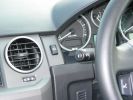
Spot / Driving Lamps Switch382 views
|
|
Spot / Driving Lamps Switch440 views
|
|

D4 headlight switch connector27 views
|
|

D3 Rear Tailgate switch headliner connector8 viewsThe black connector in the headliner of a D3, showing the brown wire being pushed back and not making contact, and stopping the rear button from working
|
|

39 viewsRear, switched, always live dual USB charging socket
|
|

3 viewsSW Switches
|
|
Spot switch (end)35 views
|
|
Spot switch (side).39 views
|
|

46 views
|
|
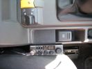
CB by EPB Switch191 views
|
|

Part numbers for JAE connectors for the upper hatch switch. 382 viewsThis lists the JAE and Digi-Key part numbers for the electrical connectors for the hatch switch.
I contacted Japan Aviation Electronics and they directed me to Digi-Key in the USA who sell odd lots of the JAE product, odd lots meaning two pins and one connector if that is all you wish.
|
|

JAE connectors for the upper hatch switch and FAKRA connectors for the Sat NAV.539 viewsThis jpg shows some catalog pages listing the MX19 connectors used on the upper hatch switch.
Also shown are the FAKRA connectors that are used on the rear of the Sat NAV.
|
|

Replacement switch from RRS installed on LR3864 viewsThe switch shown is LR part number YUZ500020, the upper rear hatch release switch that is found on the Range Rover Sport.
The switch body is the same switch as on the LR3 except that there is no wiring disconnect on the LR3. Hence when the switch corrodes and requires replacement, the LR solution is to purchase a new handle and license plate light assembly. I instead cut off the old switch and installed a JAE mating connector to the existing wiring and hence just plugged the RRS switch in.
The replacement RRS switch snaps into the same rectangular space in the same manner as the removed LR3 switch, the difference is the JAE male wiring connector.
|
|
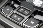
24 views
|
|
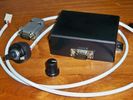
New switch186 viewsRotary switch and module box
|
|
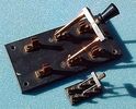
20 views
|
|
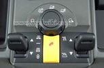
Thread upload14 viewsImage uploaded in thread 156500
|
|
Thread upload17 viewsImage uploaded in thread 156500
|
|

Thread upload6 viewsImage uploaded in new thread
|
|

Thread upload4 viewsImage uploaded in new thread
|
|

Thread upload7 viewsImage uploaded in new thread
|
|

Thread upload1 viewsImage uploaded in thread 209420
|
|
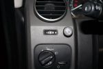
Switch for Hella 4000 Compacts303 viewsDriving lamps are integrated with the high-beams or can be overriden with this switch.
|
|
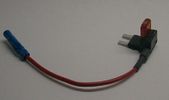
Littelfuse Mini Add-A-Circuit FMH200BP and OFH0200ZP1621 viewsFound this jpg somewhere on the forum - others are using them as it is a good way to tap the fuse box to add a fused circuit, or in this case, to modify a circuit to add a switch such that the fused circuit is switched. In my SmoothTalker gallery, there is a PDF from Littelfuse specifically related to this Add-A-Circuit device.
Before you install the Add A Circuit for any application, take an ohm meter and trace out the circuit path of the two pair of slots that fuses could insert into. The path is more complicated than one might first think. As such, the orientation of the fuse holder in the socket may matter depending upon the application. If the application is a circuit diverter, (as the F35 mode is), as opposed to a mere accessory adder, orientation matters.
|
|

LR Electric Trailer Brake C2590 Female Connector606 viewsThis female connector, C2590, located up above and near the brake pedal is for the Trailer Electric Brake Controller hookup.
The Black wire in the bottom right is pin #3, the ground. The Blue wire to the left is pin #6, the Trailer Brake Controller output going to the rear trailer socket.
The White #4 wire is the 30 amp fusible link, (Link 6E in the engine compartment junction box), for the Brake Controller 12VDC power feed from the battery. Note that this would make a pretty good power source for CB radios and the like if no electric trailer brakes were required.
Pin #5 is a Green wire from the stop lamp switch, (the control input for the Brake Controller).
This plug is standard on all NAS (LR3) vehicles, but unlikely to be found on the D3 spec units.
|
|

Thread upload14 viewsImage uploaded in thread 124306
|
|

Bonnet Alarm Sensor17 views
|
|
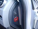
Air Suspension ECU Fuse 35P cut off switch.3820 viewsThis shows the SPST rocker switch mounted in the blank plate installed in lieu of a manual passenger side air bag shut down switch - now automatic via passenger seat pressure switch. Fuse 35P (5 amps) is located in the interior fuse box behind the lower glove box and protects the ignition power supply to the Air Suspension ECU. When the SPST switch is moved to the OFF position, the RAISE /LOWER switch on the centre console is not powered, and hence does not function. As such, some signals from the wheel height sensors and CPU are ignored. By itself however, removing F35P will probably not stop the 3 from self dropping, particularly after the engine is turned off.
Fuse F3E, (5 amps), located in the engine bay fuse box by the starting battery protects the circuit that provides feedback to the Air System ECU indicating that the Compressor Relay has successfully operated and that the Air Compressor is or should be operational, can also be removed, (but is probably not totally necessary), as it gets its power thru F26E. Hence Fuse F26E, (20 amp), also located in the engine compartment fuse box is the fuse that must be removed. This fuse protects the circuit that provides full time battery power to the Air System ECU. When in place, current thru the fuse powers the periodic re-levelling action, (usually lowering a bit with that brief air release noise), that often occurs when the vehicle is parked and the engine is off.
Removing F26E fuse will stop the auto levelling action and also inhibit any other down to the stops signals, (engine running or not). When F26E is removed, no power can flow thru to F3E, hence removing F3E is more for insurance than an absolute requirement. The same with F35P, removing F26E removes primary full time power from the Air Suspension ECU, and hence removing the F35P fuse should not really be required either as long as F26E has been removed.
|
|
Air Suspension ECU Fuse 35P Shut Off Switch2635 viewsA more distant view of the shut off rocker switch in the ON position which is the normal position for when all is working as Land Rover intended.
Ideally, (but not totally necessary), the F35P circuit should be powered or de-energized after the various computers have gone to "sleep".
Similarly, removal of the F26E or F3E fuses is preferable after the computers have all gone to sleep but it appears that no real damage will be done if the fuses are removed while the system is energized. Pulling F26E is the main full time fuse that powers the air suspension computer. As such, once F26E is removed, pulling F3E is not really required.
Power for the compressor goes thru the 60 amp fusible link and relay, however control of the relay is via the air suspension computer so depowering the air suspension computer effectively depowers the air compressor and the internal exhaust valve relay/port.
|
|
Battery Maintainer switch box and connector 722 viewsThe Hammond box contains a DPDT toggle switch with centre off. The Positive and Negative from each battery feeds to the switch. Depending on the setting of the toggle, (full left, full right,or centre off),the respective batteries connect into the pigtail that can stick out thru the grill when one wishes to connect the charger.
This allows one to charge each battery independently via a suitable battery maintainer. I use a CTEK unit that feeds a maximum of 3.3 amps at 14.4 or 14.7 VDC, depending upon setting. The wiring therefore allows for a slow recharge of either of the batteries separately if either one requires such.
|
|
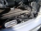
Battery Maintainer switching box plug and CTEK Multi US 3300 charger. 706 viewsThe CTEK Multi US 3300 maintainer is just sitting there for the picture. In addition to topping up both batteries, the CTEK can provide power such that if the batteries were completely dead, there would be power to the door locks and hence, one could most likely still gain access via the remote once the starting battery charged up a bit.
The Land Rover recommended method is via the hidden key hole which is mechanical, however that presumes the mechanism is not frozen from lack of use. As such, the manual lock should be exercised at least once a year to ensure that it still functions.
The blanking plug sitting on top of the plastic box is of the GM Weather Pack series. That is what I like to use for vehicle wiring that is subject to moisture, (or not).
|
|
Boot lighting panel, finish side up 309 viewsThe above jpg shows the two 15 LED light assemblies as well as the SPST rocker switch mounted beside the W5W Land Rover supplied light.
The reality is that with the recent development of LED lighting that can replace a W5W T10 bulb, one can almost achieve the same results just by installing a LED bulb within the factory light.
|
|
Boot lighting panel, wiring side up 281 viewsThis shows the back side of the plastic cover panel on which the two LED lights are mounted.
Also of note is the SPST rocker switch to switch the new lights off independent of the the Land Rover W5W light.
The new light pair will only power up if the Land Rover light is powered and hence dims and automatically goes off along with the Land Rover light.
The Black wire is ground, the Purple wire is +12VDC.
|
|
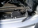
Plastic cover and Box back on in Front of Radiator 637 viewsThe wiring loom is below the cover - nothing is crushed or distorted and all fits back together OK. The black plastic box with the DPDT, (centre OFF), toggle switch is to tie the battery maintainer to each of the two batteries per the Traxide Dual battery install. I can also get power to the power door locks if all fails.
|
|
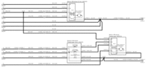
Power Window Circuit Sheet 2 Central Junction Box to Passenger Front Switch365 views
|
|

Power Window Circuit Sheet 3 Central Junction Box to Rear Switches391 views
|
|

we put the fuses in the rear panel as well as the air tank gauge, air switch, and battery switch.417 views
|
|
rear hatch light and door release switch390 viewswe\'ll ad a switch "guard" to protect from accidental gear shift popping button. light is slider 3 way so unlikely to be turned on by accident but will be nice down light when hatch is opened out.
|
|
a few items being built in behind cover panel.442 viewsred inverter will have fluch mount plugs, air outloet will be flush, guage with window in lower pop-panel and switches and fuses for all rear items behind popout panel.
12v sockets being added as well, high and low.
|
|

Air Suspension Wiring Sheets3037 viewsThese two sheets show the wiring and fuses related to the operation of the air suspension system. Fuses F3E, F26E, and F35P are shown as well as the interior up down switch and the wheel height sensors.
As with all pdf's, you can rotate them to view plus download and or print out as you wish.
|
|

Land Rover Brake Light switch XKB5001102699 viewsThis is what the switch looks like when removed from the parts box. Note that the plunger is recessed back into the body and when installing, the process of rotating the switch body 1/4 turn anticlockwise releases the plunger so it pops longer and engages the brake pedal. If you look down on the plunger you can see curved slots where the rotation takes place.
Do not try to rotate the new one - play with the one you remove. Also do not press on the brake pedal when removing or installing as you will damage the plunger - this is one of the reasons the plunger is retracted into the body for installation. It is also for this reason that if you try to confirm the operation of the switch contacts with an ohm meter by pressing the plunger, the switch will appear not to function as one might anticipate. Have faith, the switch will however, once installed and the plunger is in full motion.
|
|

Stop Light Lamp Circuit pdf2491 viewsThis pdf shows the brake light circuit for the NAS LR3.
Note that power for the brake light bulbs can come either thru the brake light switch power feed /contacts plus also from the Hill Decent Control, (HDC), system relay located within the Central Junction Box, (CJB) - yes two separate sources of power for the brake light bulbs. This would tend to explain how a brake light circuit concern shows up as a hill decent fault message; also why lesser vehicles without hill decent braking mechanisms, (HDC), never display this sort problem when a brake light bulb or switch acts up. You never have a problem related to a system that does not exist.
Additional evidence of the relationship of the HDC and the tail light circuit is demonstrated by when the HDC actually acts to slow the 3 down, the brake lights automatically illuminate even if the slowing action was merely retarding the engine speed or shifting to a lower gear, (in other words, no foot on the brake pedal).
There is also a tie in to the Cruise Control and hence a failing brake light switch can affect cruise operation or just create false Cruise Control messages. To further complicate the issue, while there are no messages generated, operation of the radiator electro viscous fan can also be negatively affected by the fouled set of secondary contacts within the brake light switch. This is all because the NC contacts within the brake switch send misleading messages to the ECU.
While the ground wire design is similar to other vehicles, note the grounds for the brake light filament and the reverse light filament are common on each side. That means that if one has a non functioning brake light on one side, the reverse light may not also work or that some problem with the reverse lights could back feed into the brake lights. This situation while unusual, can result when grounds are corroded probably due to swimming in rivers and creeks or just routine driving in a marine environment.
|
|

Thread upload5 viewsImage uploaded in new thread
|
|

Thread upload7 viewsImage uploaded in thread 108732
|
|

Thread upload4 viewsImage uploaded in thread 40682
|
|
Thread upload26 viewsImage uploaded in thread 113350
|
|
Thread upload29 viewsImage uploaded in thread 113350
|
|

LTB00133 - Technical Bulletin - Low Engine Coolant Level Switch - Lower Level Service Part Availability81 views
|
|

Thread upload9 viewsImage uploaded in thread 125684
|
|

Thread upload1 viewsImage uploaded in thread 198354
|
|

Thread upload4 viewsImage uploaded in new thread
|
|
Thread upload8 viewsImage uploaded in new thread
|
|
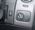
No 2 Light Switch and my Bezel37 views
|
|

oil switch9 views
|
|

oil switch thread10 views
|
|
Thread upload4 viewsImage uploaded in thread 199186
|
|

Thread upload6 viewsImage uploaded in thread 126959
|
|

Thread upload6 viewsImage uploaded in thread 126959
|
|
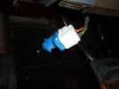
brake light switch3655 views
|
|
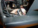
brake light switch3215 views
|
|
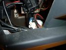
brake light switch2208 views
|
|
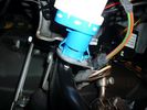
brake light switch3663 viewscommon failure, replace with newer one marked fomoco
|
|
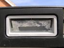
Corroded rear door switch253 views
|
|
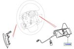
74 views
|
|

Thread upload2 viewsImage uploaded in new thread
|
|
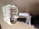
Brake Light Switch Guts - Black Soot46 views
|
|

Tow Bar Switch upgrade7 views
|
|
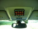
544 viewsSwitchboard and the camera
|
|

Thread upload17 viewsImage uploaded in new thread
|
|

LED Switch78 views
|
|
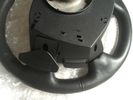
Thread upload5 viewsImage uploaded in new thread
|
|
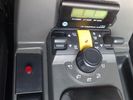
reverse toggle switch94 views
|
|

Ride & Handling Switch91 views
|
|

Thread upload2 viewsImage uploaded in thread 209420
|
|

Thread upload2 viewsImage uploaded in thread 209420
|
|
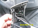
Steering wheel Switches46 views
|
|
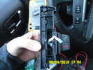
Steering wheel Switches45 views
|
|
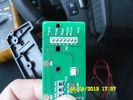
Steering wheel Switches43 views
|
|
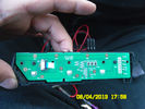
Steering wheel Switches46 views
|
|
Steering wheel Switches39 views
|
|
Steering wheel Switches44 views
|
|
Steering wheel Switches44 views
|
|
Steering wheel Switches42 views
|
|
Rear audio switch36 views
|
|
Door switch flipped34 views
|
|

Thread upload2 viewsImage uploaded in thread 202349
|
|

Thread upload2 viewsImage uploaded in thread 186843
|
|
Thread upload7 viewsImage uploaded in thread 133325
|
|

Brakelight Switch26 views
|
|
Thread upload0 viewsImage uploaded in new thread
|
|

58 views
|
|
source selector111 views
|
|

92 views
|
|
14 views
|
|

EPB fault12 views
|
|

Thread upload0 viewsImage uploaded in thread 154179
|
|

Thread upload6 viewsImage uploaded in new thread
|
|

Thread upload13 viewsImage uploaded in thread 177861
|
|

Thread upload0 viewsImage uploaded in new thread
|
|
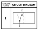
Thread upload2 viewsImage uploaded in thread 198012
|
|

Thread upload0 viewsImage uploaded in new thread
|
|

Thread upload0 viewsImage uploaded in thread 208995
|
|
Thread upload4 viewsImage uploaded in thread 176204
|
|
Thread upload2 viewsImage uploaded in thread 176204
|
|

Thread upload3 viewsImage uploaded in thread 142922
|
|
Thread upload10 viewsImage uploaded in thread 122671
|
|
Thread upload4 viewsImage uploaded in thread 122671
|
|
28 views
|
|
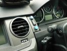
Additional Switches243 views
|
|

Thread upload28 viewsImage uploaded in new thread
|
|

Spot light switches20 viewsImage uploaded in thread 40682
|
|

40 views
|
|

57 views
|
|
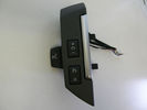
32 views
|
|
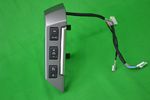
34 views
|
|

Thread upload2 viewsImage uploaded in thread 154757
|
|

Switch in Cabin63 views
|
|
Thread upload10 viewsImage uploaded in new thread
|
|

Thread upload0 viewsImage uploaded in thread 202149
|
|
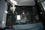
4x4 channel video switch (low) + alpine 425i on top left135 viewsmy car is 5 seater, so there is room under the seats...
|
|

Thread upload14 viewsImage uploaded in thread 177861
|
|
Thread upload3 viewsImage uploaded in thread 40682
|
|

17 views
|
|
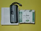
Upper Hatch Release Switch LR Part Number YUZ500020676 viewsThis is the Range Rover Sport switch, Land Rover part number YUZ500020, as it comes out of the box. Note the JAE, (Japanese Aviation Electronics), male wiring connector installed on the end of the power lead.
The rubber cover of the switch is sealed to the plastic body of the switch whereas in the previous switch design, there was no sealing. Also the replaced switch was hard wired into the same harness as the license plate lights - no JAE connector in other words.
|
|
24 views
|
|

Thread upload0 viewsImage uploaded in new thread
|
|

Thread upload0 viewsImage uploaded in new thread
|
|

Thread upload0 viewsImage uploaded in new thread
|
|
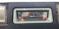
Corroded tailgate switch29 views
|
|
Thread upload22 viewsImage uploaded in thread 114391
|
|

Tekonsha Ford Brake Controller Adapter part number 3035-P274 viewsThis is the adapter cable between the Brake Controller and the existing C2590 female plug located near the brake pedal on NAS spec LR3's. The flat 4 pin plug of the adapter cable connects to the Controller; the rectangular 6 hole male plug to C2590.
There are only four conductors in the adapter cable, but one will see five pins within the Land Rover C2590 plug. The #2 pin is not required for the NAS setup. #2 pin is the circuit between the head lamp switch and vehicle side running lamps required in the civilized world.
The single pin at the bottom in the picture is #3 and on the Land Rover, a Black wire tied to ground. The other pin at the bottom and across to the left is #6, and Blue on the Land Rover. This is the Brake Controller output to the trailer socket at the rear.
#4 is the pin at the top left, and is a White coloured wire from the battery. Pin #5 is from the stop light switch, and is Green on the Land Rover.
Note that the adapter cable colours do not necessarily follow all the above referenced Land Rover colours.
|
|

Thread upload2 viewsImage uploaded in new thread
|
|
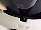
Llams - mode switch18 views
|
|
|
|
|
|
|