| Search results - "short" |
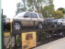
01 Start of Xmas 07 trip across the Australian Nullabor243 viewsThis is the preferred method of travelling 2500km of Nullabor desert when time is short (the Indian Pacific train). Next stop is Adelaide.
|
|

Thread upload10 viewsImage uploaded in new thread
|
|
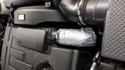
Thread upload148 viewsTemporary short term fix - duck tape to get you home!!
|
|
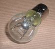
Land Rover Stop Tail Light dual filament bulb nominal 12 volt 21 / 5 watt filaments1427 viewsThis is the Land Rover part number 264590 dual filament bulb, (P21/5), that inserts into the upper two tail lamp receptacles. In the upper one, both filaments function, in the lower one, only the 5 watt tail light filament functions.
I regard it as not a good practice to routinely switch bulbs when the tail light filament, (5 watt), burns out on the lower bulb. The broken filament can jiggle over onto the brake light filament, (21 watt), and short the circuit to ground or something else not predicable.
There are also arguments to say that quality control is better on the Land Rover marketed bulbs than say far east sourced bulbs. Filament construction, and hence resistance can vary and mislead the current sensing circuits monitoring the signal light systems. Also when the bulbs are properly installed, all filaments should be standing vertically and not at any slope.
These are the sort of obscure circumstances that can lead to false trouble messages on the display, dropping to the stops, and subsequent concerns - all over a tail/signal light bulb.
For example, the filament life of both the tail light and the brake light filaments in the P21/5 bulb is significantly less than the USA common 1157 dual filament bulb, (1000/250 vs 5000/1200 hours); brightness in the P21/5 is a bit more, (3cp/35cp vs 3cp/32cp where cp is candle power), but current consumption is oddly less, (0.44a/1.86a vs 0.59a/2.10a where a is amps). It is the quest for efficiency vs maintenance trade off.
|
|

Engine Accessory Drive Description and Operation882 viewsThis 2 page pdf shows both belts for the 4.4L petrol V8; the primary serpentine belt, (the long one), and the shorter secondary that drives only the radiator cooling fan.
The various accessory pulleys the two belts are each associated with are numbered and an included table describes each.
When replacing belts and pulleys, count the number of grooves on both your old items and your new replacement parts. It has been known for an pulley with the wrong number of grooves to come with a replacement part or the replacement belt has the incorrect number of grooves; hence make certain the groove count on the new parts are the same as the removed items.
|
|
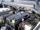
BCI Group 40R Deka 640RMF battery showing vent hose run forward to windshield washer reservoir area 1430 viewsRecessed post "Euro profile" battery to "match" OEM and stock Land Rover bracket; note that the Traxide SC80-LR module is mounted at an angle to allow for the main cable to sit under the cover so cover still closes.
The battery is a nominal 7", (180mm), high, but sits on a 1" battery spacer set under to raise the bottom front end of the battery such that the approx 11", (290 mm), length of the BCI 40R battery rises above the angled plastic nibs at the forward end bottom of the case front; hence sufficient space, (1/4", 5mm) remains at the brake reservoir end.
Also the 40R battery does not have hold down "flanges" on each end; on the sides yes, but not the ends so no additional length is required.
When I had to replace the 40R, this time I installed the shorter, (9.625"), taller, (7.5") Interstate BCI 47 / DIN H5 battery which eliminated the spacer on the bottom and better fit the stock LR tie down bolt lengths. Deka also has a BCI 47 / DIN H5 that would work fine as well.
|
|

255/75 R17 BFG MT 98 viewsAccess height with shortened rods & spacers
|
|

A short stop before entering Finland. October 201029 views
|
|

crankshaft bolt24 viewsBolt on left is new one for upgraded oil pump casing. Bolt on right is what came out. Notice damaged end and shortness of bolt. Inside of crank was inspected wirh borescope and threads etc all ok. New bolt goes in and out ok. Few filings inside but otherwise clear. Not sure why old bolt ended up like that.
|
|
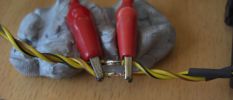
Can Pair Repair84 viewsThis is the high speed CAN bus Pair. By over twisting and keeping the repair short i will maintain the very important twist. Good soldering is a must it looks ropey in this shot but it is not, note the heat shrink pre placed on the wires to the right.
|
|

Can Bus14 views0s - Start of trace
5s - unlock 1
10s - ignition on (In-I-II)
30s - ignition off (II-I-Out)
Non accurate timings - +/- ~2s.
|
|
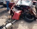
MERC CLK AMG - bit bent149 viewsThis is the short version. A bit of a head on bump did some major restyling.
|
|

Thread upload13 viewsImage uploaded in thread 137470
|
|

181119 viewsif it had a P infront of the code it would be Four-wheel drive low ratio - short circuit to ground
|
|

D3 Shorty193 views
|
|

27 viewsShort clip of turbo actuator rod moving after key turned to position2/3
|
|

D/3/4 wheel stud aligner11 viewsPDF drawing of dimensions to manufacture your own.
Alternatively, I can do it for you.
( One for Defender coming shortly)
Suggestions welcome.
|
|

The finished left board at a short distance52 views
|
|

The finished left board at a short distance63 views
|
|

Short stop on Merricumbene FT - while a tyre was changed77 views
|
|

The camp site - from a short distance up the Dampier Mountain Fire Trail.78 viewsThere is a silver D3 in the photo - belonging to eran48.
|
|
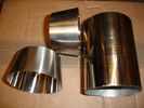
10 views2 reducing cones and short length of pipe ordered from the bay of evil
|
|
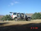
packing up to leave, note short suspension hieght rods not removed yet123 views
|
|

Patriot short rack used as a wheel carrier52 views
|
|

Fluid, Filter/Pan Combo removal and install5979 viewsThese are the LR instructions re removal and install of the plastic pan/filter combo for the ZF 6HP26X transmission on the 4.4L petrol V8 LR3.
The instructions tend to ignore the reason you have to lift the right hand side of the engine about 40 mm. This is because of a frame cross member that interferes with dropping down of the plastic pan. The real problem is a vertical "oil filter spout" that rises out of the filter/pan combo up into the transmission. The spout is the suction pipe for filtered transmission oil back up into the tranny.
On the metal pan versions, the filter is separate from the pan, hence the filter remains with the tranny when the metal pan is dropped. The filter is then removed or installed independent of the metal pan, hence with the metal pan, there is no need to lift the engine.
If one is removing the plastic pan so as to install the metal pan, then some do not lift the engine but just drop the plastic pan enough to gain access to saw off the vertical plastic spout - it is a one time procedure.
Be aware however that the metal pan uses a flat gasket and the plastic pan uses a O ring like perimeter gasket that sits in a half round groove in the tranny casing. Also the metal pan uses 21 shorter torx M6x22.5 metric cap screws for the perimeter bolts. The plastic pan uses longer M6x28.5 torx metric cap screws.
|
|

Thread upload3 viewsImage uploaded in thread 186018
|
|

68 viewsA short trip to the French/ Italian Alps.
The boy isn't quite big enough to ski just yet.. maybe next year..
|
|
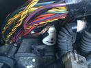
Harness chafing19 viewsWire insulation worn through with short to battery
|
|

LP scoped 222 viewsBy connecting a Low Amps probe to the fuel pump's voltage supply wire, you can view the pump's current waveform on a digital storage oscilloscope (DSO). The scope pattern will reveal internal wear in the brushes and commutator that may not show up in a traditional pressure or volume test.
Observing the waveform will show if the pump's amp draw is normal for the application or is high or low, and if the pump is operating at normal speed or is running slow. Problems such as a bad spot on a commutator or a short or open in the armature also will be obvious in the waveform.
A "good" electric fuel pump waveform will generally seesaw back and forth with relative consistency and minimal variation between the highs and lows. A "bad" waveform will show large or irregular drops in the pattern, with large differences between the highs and lows.
|
|

B1591 324 viewsB1A56-11
Antenna - Circuit short to ground
Diversity antenna amplifier circuit short to ground
Refer to the electrical guides and check the diversity antenna amplifier circuit and the antenna for short circuit to ground
|
|

235 viewsShort outing outside the house and away.
|
|

94 views
|
|

Thread upload8 viewsImage uploaded in thread 176078
|
|

LLumar AIR80 Air Blue 78 windscreen film IR reduction metal oxide340 viewsThis pdf summarizes the characteristics of the various types of window glass film available from LLumar. www.llumar.com
I had the Air 80 metal oxide sort of clear film, (windshield film they call it), installed on the front driver and passenger side windows to reduce the Infra Red penetration and hence heating effect on the front occupants. The film is barely visible from either inside or outside, however there is a noticeable reduction in heat penetration when sitting inside. In short, my arm does not get cooked.
Cell phone and GPS etc seem unaffected by the metal oxide film.
I also had the film installed on the three sun roof portions as well.
|
|
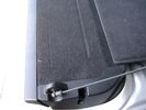
Flexible wire rope fishing leader 0.032" diameter exiting carpet 1948 viewsThis is all you see of the completed mod.
The short little angled "line" about an inch long that looks like a piece of debris and is located a few inches "above" the support cable is actually the wire rope release cable exiting from under the carpeted lift gate cover.
I drilled a very small hole in the carpet and pushed the 0.032" diameter release wire thru and then slipped the loose end under the black plastic.
To release with the lift gate etc closed, from the inside, just pull the loose end free from under the black plastic and gently pull wire about 5mm, (1/4"), and the upper door catch should release. You will have to manually push the upper door out wards to actually effect opening, but you will already be inside the rear cargo area so that part is easy to do.
The assumption is that the lower door latch still works electrically and hence, the lower lift gate half will open as normal by pressing the usual button on the top left of the lower door half.
|
|
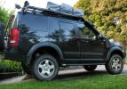
lifted with shortened "arms"289 views
|
|

LR3 and 4 NAS hitch receiver original and newer third generation.773 viewsThe picture shows the original 2005 model "plow" for the LR3 and the newer shorter hitch receiver introduced with the LR4. Either receiver can be used on the LR3/D3; they are interchangeable.
The part number of the newer third generation short style is LR019990 replacing previous long type part number KNB500080. There were two versions of the longer one, KNB500080 with the orange key, apparently a better locking setup. The first generation, KNB500023, with a black key was less than perfection.
The green lock assembly with orange key, part number KNW500010, shown on the shorter hitch, can be purchased separately should a key be lost.
Regardless of receiver model, the receiver will accept nominal NAS 2" tongue on which may be mounted the appropriate ball size.
|
|

LR3 Brake Wear Sensor Wiring1517 viewsThis 1 page wiring diagram pdf shows that both the front and rear brake pad wear sensors are part of a closed series circuit to ground.
In operation, when all is good, the series circuit is grounded and the amber brake wear warning indicator on the instrument panel is not illuminated.
When the pads on one wheel, either the left front, or right rear, become too worn, the respective sensor is "cut" which results in an open circuit condition. This causes the dash brake wear indicator to illuminate.
The circuit is like the old style Christmas light strings where one burned out bulb caused the whole string to go out.
A quick field fix to get the dash light to extinguish in lieu of replacing the sensor and pads etc is to disconnect the brake pad wear sensor and short across the two open conductors of the vehicle side connector plug. This of course means you now have a normal vehicle, one of the thousands that do not feature brake pad wear information systems.
|
|

Mirror shell replaced - notice self tapping screws52 viewsMirror shell replaced - notice self tapping screws to replace "plastic rivet heads" and also washers on inner screw to prevent screw piercing mirror housing due to short hole.
|
|

ZF 6HP26 Land Rover Transmission specs1677 viewsThis is just two sheets of paper with various numbers related to the 6HP26 such as oil capacity, gear ratios, and torque wrench settings for the fill and drain plugs.
You may note that LR calls this ZF transmission the 6HP26 whereas ZF calls out the LR3 transmission as the 6HP26X. Just what the differences are, I am not certain however the X refers to 4WD or AWD use as opposed to solely 2WD.
Zahnradfabrik is what ZF is short for and translated from German, roughly means Gear Factory.
|
|

LTB00125 - Technical Bulletin - 4.4L V8 Short Engine Availability61 views
|
|

Lug Nut part number RRD500290 outline sketch541 viewsThis single sheet pdf provides dimensions of the LR part number RRD500290 lug nut on vehicles from MY 2005 to 2008, (up to VIN 8A450459). From VIN 8A450460, the part number is RRD500590.
Visually, there is no apparent difference between the two part numbers. The dimensions appear identical as well. The shape, size, and profile of the Stainless Steel "hat" appears identical.
There are I presume differences in metallurgy to reduce corrosion and swelling of the hat or perhaps better sealing between the inside surface of the hat and the steel of the lug nut body. The reality is the differences are not immediately obvious however.
A 22 mm six point half inch or larger socket drive fits over the lug nuts. I use a nominal 36" long breaker bar with the 22mm socket - any shorter bar, best you be in shape. Depending upon your source, for both alloy and steel wheels, the lug nut torque value appears to be 103 lbf ft, (140 Nm); others suggest first tighten to 96 and then finish at 110 lbf ft, (130 and 150 Nm).
|
|
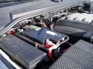
Main starting battery showing 1/2" hole drilled for power cable egress909 viewsView of OEM battery in Left Hand Drive LR3. This is supposed to be a Battery Group BCI 49 or H8 sized battery but in reality is the slightly shorter BCI 94R or H7 battery that fits easier lengthwise, (12 3/8" vs 14").
Note the 10mm hole drilled in plastic of surround to allow for entry of main power cable that runs between batteries. The cable bolts to a spare 6mm threaded hole in the OEM battery cable end; the light gauge wire runs to the front of vehicle to a connector for the CTEK MULTI US 3300 charger. Coloured felts, (red and green), are a material treated to reduce battery post corrosion. The OEM battery ground cable is only about a foot long and runs to an 8mm stud located on the inner fender just to the rear of the fuse case.
|
|

Yes, that is Marilyn in better days.1594 viewsIf she had just been content to fool around with blokes who liked Land Rovers ...
|
|

131 views
|
|
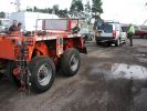
50t capacity trailer for D3 !!!80 viewsD3 comes in handy for splitting away 2 axles of a larger modular hydraulic heavy haulage trailer, just delivered an 80t transformer for me into Scotland, and we shortened the trailer for the journey back to Italy.
|
|

start of the day417 viewsVery nice selection of Rovers attended the trials. I had the only LR3. The had two classifications, short wheel base (under 100 inches) and Long Wheel base (over 100). LR3 was classified in the long.
|
|
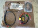
Traxide SC80-LR656 viewsKit -- cable was 6 feet short. Check to ensure the length is adequate prior to installing it.
|
|
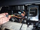
original MOST cable123 viewsreplace the short cable from Radio to Nav display with part of the additional MOST loom (YMQ502470)
|
|

BUMPER DUMPER NEVER BE CAUGHT SHORT123 views
|
|

RRS Shorty176 views
|
|
Thread upload6 viewsImage uploaded in thread 184680
|
|

new shiny silver97 viewsRRS 2012MY
aka D3 short
|
|

Short57 views
|
|

131 views
|
|
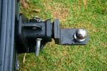
Shortened 299 viewsAfter removing 35mm from the tongue plug
|
|
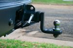
Shortened 100 viewsAfter removing 35mm from the tongue mount
|
|

122 views
|
|

14 views
|
|

Thread upload1 viewsImage uploaded in new thread
|
|

school bus110 views
|
|

Short clip number 2, bit wobbly but my 7 year old was filming!558 views
|
|

Short clip, bit wobbly but my 7 year old was filming!463 views
|
|

Botswana188 viewsShort river bed time trail.
|
|
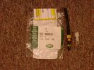
Voss System 203 connector 6 mm for valve blocks 905 viewsThis is Land Rover part number RQC000030, the Voss fitting for the axle valve blocks. I think it is a Voss System 203 6mm fitting, Voss part number 5 2 03 11 01 00.
The parts bag comes with the white plug inserted in the brass threaded bit with what is called the brass cutting ring placed on the tip of the white plastic plug. The idea is that one screws, (M10 x 1 thread), the brass insert into the appropriate hole with the white plug still in the brass insert. Once the brass is tight, (12 mm wrench), then the white plug is pulled from the assembly leaving the cutting ring down inside and under. One then pushes in the 6 mm tube end about 20 mm or so and the tube slides down thru the brass cutting ring, (2 internal sloped one way cutting ridges). When the tube is in far enough, one pulls upwards a bit and the ring cuts into the plastic such that the tube will not pull out. To remove tube, one unscrews the brass nut and all comes out, sort of like I have shown with the short piece of 6mm tubing. The white plug is a throwaway item upon install of the tubing.
|
|

MS Word Keyboard shortcuts155 viewsFor those that prefer to use keyboard shortcuts when working with MS Word - here is one I prepared some years ago.
|
|

ZF 6HP26 Metal Pans, (top and bottom views), and separate Filter top and bottom views.1765 viewsThis single sheet pdf two views of the ZF metal pan for the 6HP26 transmission. The inside view shows the two magnets; the other is the bottom view. Also visible are the transmission bottom oil fill and oil drain holes that are sometimes utilized where access to the side fill is not possible. The ZF part number for the metal pan kit for our 6HP26X six speed is 1068_103_820_01 This includes the 21 shorter Torx screws, the metal pan gasket, and the separate oil filter as well as round filter seal. The ZF six speed LifeGuard6 transmission oil is extra.
|
|
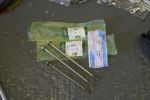
Two long bolts do not help when you need a short bolt!123 views
|
|
|
|