| Search results - "replace" |
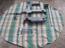
The full complement of bits and pieces, major parts back from the powder coaters, all bolts nuts washers replaced with stainless steel241 views
|
|
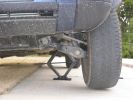
Jacked-up, loosened bolts, ready to replace.444 views
|
|

Thread upload36 viewsImage uploaded in thread 106250
|
|

TB 149584 - Air Suspension Compressor and Relay Replacement41 views
|
|
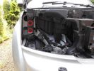
Remove Headlights and Grille using bulb replacement instructions in Manual - Push the fixings supplied into these holes circled in red152 views
|
|
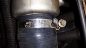
33 viewsNearside hose replaced with silicone type
|
|
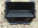
Rear Console trim which i replaced with one with heated rear seats.11 views
|
|
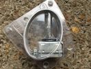
Used Xeno Bulbs from MY2011 Commercial - replaced with Higher capacity7 views
|
|
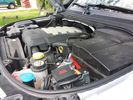
Winch Power upgrade318 viewsUsing 2 warn kits, and removing one of the wires to use on another project. The purpose was to replace the power and ground wire. I used Warn kits, which are 4/0 Welding cable. The original red #4 warped from getting a little too worn. The 2nd
Battery #1 Deka 9A94 AGM Intimidator, Battery #2 Deka 9A47 AGM Intimidator WARN 36080 28" Quick Connect Cable X 2, WARN 26405 Quick Connect Cable 7' X 2, WARN 15901 Black Cable X 1 -- winch control 72" X 1 https://www.facebook.com/DifferentialPartsUS
|
|

Thread upload5 viewsImage uploaded in thread 206795
|
|

Thread upload4 viewsImage uploaded in thread 206795
|
|

Engine Accessory Drive Description and Operation882 viewsThis 2 page pdf shows both belts for the 4.4L petrol V8; the primary serpentine belt, (the long one), and the shorter secondary that drives only the radiator cooling fan.
The various accessory pulleys the two belts are each associated with are numbered and an included table describes each.
When replacing belts and pulleys, count the number of grooves on both your old items and your new replacement parts. It has been known for an pulley with the wrong number of grooves to come with a replacement part or the replacement belt has the incorrect number of grooves; hence make certain the groove count on the new parts are the same as the removed items.
|
|
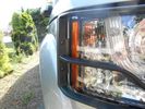
Replace the headlight and then fasten the light guard using the two allen bolts322 views
|
|
Fit the 2nd lightguard and then replace the centre grille330 views
|
|
Thread upload39 viewsImage uploaded in thread 102519
|
|
Thread upload2 viewsImage uploaded in thread 177818
|
|
Thread upload0 viewsImage uploaded in thread 177818
|
|
Thread upload1 viewsImage uploaded in thread 177818
|
|
Thread upload0 viewsImage uploaded in thread 177818
|
|
Thread upload1 viewsImage uploaded in thread 177818
|
|
60 viewsOne bolt is visible at the front, but the other two are down the left hand side and best accessed by removing the small plastic guard behind the bumper. I also removed the small metal radiator guard between the bumper and the main sump guard (but that was mostly to retrieve the spanner I dropped!). The only issue with removing the plastic guard is the stupid plastic clips that hold it on may need to be replaced.
|
|

Compressor type TSB109 viewsLand Rover TSB regarding Compressor type identification and fitment.
|
|
Cables being replaced23 views
|
|
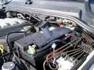
BCI Group 40R Deka 640RMF battery showing vent hose run forward to windshield washer reservoir area 1430 viewsRecessed post "Euro profile" battery to "match" OEM and stock Land Rover bracket; note that the Traxide SC80-LR module is mounted at an angle to allow for the main cable to sit under the cover so cover still closes.
The battery is a nominal 7", (180mm), high, but sits on a 1" battery spacer set under to raise the bottom front end of the battery such that the approx 11", (290 mm), length of the BCI 40R battery rises above the angled plastic nibs at the forward end bottom of the case front; hence sufficient space, (1/4", 5mm) remains at the brake reservoir end.
Also the 40R battery does not have hold down "flanges" on each end; on the sides yes, but not the ends so no additional length is required.
When I had to replace the 40R, this time I installed the shorter, (9.625"), taller, (7.5") Interstate BCI 47 / DIN H5 battery which eliminated the spacer on the bottom and better fit the stock LR tie down bolt lengths. Deka also has a BCI 47 / DIN H5 that would work fine as well.
|
|

A Pillar Black Plastic cover install pdf - new type.1039 viewsThis 3 page LR pdf explains how to install the newer A pillar plastic covers and avoid instant water leakage as a result of the new design.
|
|

OLD VERSION - Bodsy's Brake Bible v 1.611172 viewsUSE Version 1.6a
Clarified EPB shoe instructions & corrected references to other sections. Added paypal donations information (requested by users of the guide.) Internationalised wheel location references by removing UK based reference to OS/NS, replaced with physical Front Left or Front Right descriptions.
|
|

Black Deposits to interior of Brake Light Switch2861 viewsThere are two contacts, one on each side of the vertical plunger under the copper metal. The set of normally open contacts on the left side that carries the power for the brake light filaments, (15 amp fuse F15P), is apparently not heavy enough as the contacts deteriorate and generate the black residue.
The set of normally closed contacts on the other side appear to be sized OK. There is not as much current, (5 amp fuse F66P), flowing thru the contacts to the ABS module, however the contacts are likely adversely affected by the black residue produced by the other deteriorating set of contacts.
One presumes/hopes that the newer replacement switch now has contacts heavy enough to carry the brake light power. It would be ideal if the ABS set of contacts were sealed from the brake light contacts to prevent contamination of the normally closed set of contacts.
|
|

Brake Light Switch, Find, Remove, and Install Instructions 7853 viewsThis is a two page doc outlining where to find the brake light switch, how to remove it, and then install the new one.
Note, do not move the brake pedal when removing or installing the switch. Let the brake pedal hang where it wants to. The switch design is actually cunning, and as such is supposed to make the removal and install fool proof. Hence if you think too much about it, you can wreck the new switch.
If you want to inspect the interior of the switch, wait until you have removed the old switch. You can then just unsnap the blue from the white to get it apart. Inside, the switch is quite simple, (no circuit boards), but it will probably show black dust from failing contacts.
I think the reason the switch fails is that the Normally Open, (NO), contacts of the brake light contacts were made too light to carry the current load for make and break of the tail light filaments. I also think the black dust created then fouls the Normally Closed, (NC), second set of contacts for the ABS circuit. As such, the Normally Closed contacts become intermittent in operation and display as a fluctuating open and closed circuit condition to the ABS system when the ABS should be seeing a steady closed circuit. Hopefully the replacement switch contacts are more robust and may be as I recently replaced my switch again just as a matter of maintenance. While in a redesign, ideally the NC contacts should be sealed or at least separated from the NO contacts, when I inspected the removed switch, this time there was no black dust present.
Probably the removed switch will have a Land Rover oval logo moulded into it, the new one, FOMOCO.
|
|
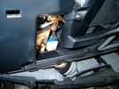
Brake Switch Visible thru Opening4975 viewsThe blue and white bit is the switch; the sort of gold appearing box,(it is really black), you will not see in your 3 as it is a Smooth Talker brand amplifier for my Blackberry phone antenna. This install is detailed in the SmoothTalker phone antenna section of my gallery.
One way to remove and install the switch is to lower the "horizontal" panel above the brake pedal as shown where the flashlight head is located. To actually remove the switch, you slide your hand thru the gap and rotate the switch clockwise 1/4 turn while watching thru the rectangular opening. Installation of the new switch is the reverse of above - 1/4 turn counterclockwise.
Before you remove the switch, note its orientation - horizontal with electrical wires to the left. That is the way it should look after replacement as well.
The second time I replaced the switch, I did it all thru the rectangular opening and did not remove the horizontal panel - that is experience helping out.
The knee kick you have to remove regardless. It is sort of hinged at the bottom so you just pull at the top and sort of rotate the knee panel and then pull upwards for two plastic "fingers" to clear the slots they reside in.
|
|
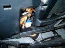
Smooth Talker Amplifier Box mounted below near steering column.179 viewsThe gold look box due to the lighting, (actually black), is the antenna amplifier located near the steering column. It can be put anyway but this seemed an OK location as I ran the antenna connector cable rearward from here to the back corner of the 3 and then up to the underside of the roof glass at the rear. The blue/white thing is the brake light switch that often must be replaced. See the Brake Light Switch file within this Gallery regarding the switch replacement.
|
|

Black Deposits on Brake Light Switch Plunger2758 viewsThis jpg I got off another forum and is typical of what one will see when one opens up the removed brake light switch. The black powder is residue from arcing of one of the pair of contacts within.
Hopefully the newer switches with the FOMOCO logo moulded into the plastic are improved from the Land Rover logo marked early units, however I doubt it.
The Ford part number is SW-6572 and/or 7E5Z-13480-A as used on the 2006 to 2009 Ford Fusion's and Mercury Milan's; the Land Rover part number is XKB500110. Cost of switch could be about twenty five dollars. A previous LR part number for the switch was XKB500030, so hopefully the newer LR part number, XKB500110, reflects some improvement in reliability.
It is possible that the new switches are better as I installed a replacement 72,000 km, (45,000 miles) later, at 195,000 km (121,000 miles). When I took the removed switch apart to inspect, it was clean inside. There was no black dust - the switch looked like new, hence they must be improved now.
|
|
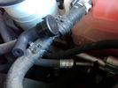
Breather line with factory cap cut off.2320 viewsIf you expand the jpg by clicking on it, in the bottom right corner if you look closely, one can see the black plastic factory vent tubing with the OEM cap cut off.
Note the tubing is cut at a 45 degree angle facing to the rear. Also shown in the top right is the cut off portion sitting on the coolant water hose and on the top left also sitting on the coolant hose, the new to be installed Gore manufactured replacement breather cap.
|
|
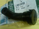
Breather Cap part # LR0194501541 viewsThis is the replacement breather cap as manufactured by the Gore Tex people, (Gore), for the engine compartment end of the front differential breather line.
You can with some difficulty, both blow and suck thru the breather filter material. The Gore Tex filter material has what are called hydrophobic and oleophobic properties. This means the filter material keeps oil in and water out, while at the same time, allowing air pressure to slowly equalize, (air permeable). Additionally, the transfer of dust, salt, and road debris is inhibited.
|
|
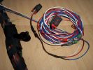
Burnt Bit97 viewsThis bit of wiring going to the connector was so close to bulkhead it got a bit burnt, Its for the clutch switch on a manual used for EPB, It will be replaced connector to pin with the wiring shown.
|
|
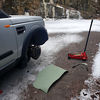
Thread upload2 viewsImage uploaded in thread 177818
|
|
Thread upload2 viewsImage uploaded in thread 177818
|
|
Thread upload2 viewsImage uploaded in thread 177818
|
|
Thread upload3 viewsImage uploaded in thread 177818
|
|
Thread upload3 viewsImage uploaded in thread 177818
|
|
Thread upload4 viewsImage uploaded in thread 177818
|
|

Thread upload2 viewsImage uploaded in thread 177818
|
|
Thread upload3 viewsImage uploaded in thread 177818
|
|
Thread upload3 viewsImage uploaded in thread 177818
|
|
Thread upload3 viewsImage uploaded in thread 177818
|
|
Thread upload3 viewsImage uploaded in thread 177818
|
|
Thread upload2 viewsImage uploaded in thread 177818
|
|
Thread upload3 viewsImage uploaded in thread 177818
|
|
Thread upload3 viewsImage uploaded in thread 177818
|
|
Thread upload3 viewsImage uploaded in thread 177818
|
|
Thread upload4 viewsImage uploaded in thread 177818
|
|
Thread upload4 viewsImage uploaded in thread 177818
|
|
Thread upload3 viewsImage uploaded in thread 177818
|
|
Thread upload2 viewsImage uploaded in thread 177818
|
|
Thread upload2 viewsImage uploaded in thread 177818
|
|
Thread upload3 viewsImage uploaded in thread 177818
|
|
Thread upload3 viewsImage uploaded in thread 177818
|
|
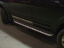
D3 Side Step Repairs165 viewsFinished job all I need to do now is wash it all off. I had already replaced the front door trim using new trim fixers and as you can see it was still dirty.
|
|
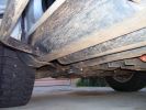
Sill protectors801 viewsThese replace the plastic sill protectors. 4mm mild steel plate, bolted through the existing holes in the side and underside.
|
|

Changing a Lower Tailgate Stay Cable.pdf8 views
|
|
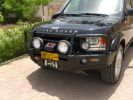
Front end327 viewsARB deluxe winch bar is very well made. Still allows Mantec sump guard to be used. Warn M8000 winch fitted - (wish I could\'ve found an M15000!) and IPF 900XS Extreme Series mounted with light stays to grille. Fog lights work fine with the replacement bumper, and indicators in bumpoer are effective too.
|
|

cleanup40 viewsI cut the branch up myself and will replace the fence when the weather clears. It snowed again after I cut it up.
|
|
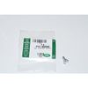
Clip Spring Metal FYC 500040 that holds LR together1747 viewsThe jpg is of the spring metal clip, Land Rover part number FYC 500040 that holds most of our 3 together - well at least most the interior trim parts.
If you are going to remove interior panels, you may as well stock up on a few for replacement as upon panel removal, the clips tend to spring away into deep never to be found voids within your 3.
|
|
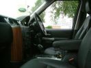
Interior124 viewsThat wood trim is going - to be replaced by piano black before I pick it up
|
|

Seat base electrics cover39 views
|
|

Front seat lower cover removal replacement43 views
|
|

Lower Seat Cover and T40 Torx bit for seat base removal47 views
|
|

Hog Rings and Hog Ring Pliers47 viewsHog Rings and Hog Ring Pliers showing an open and closed hog ring with 20p for scale
|
|

Seat Base out of car rear view38 views
|
|

Seat Base out of car37 views
|
|

Rear Seat Cover retainer - Seat Base43 views
|
|

Front and Side Clips - Seat Base39 views
|
|

Per replacement of seat base foam - note creasing on right side due to collapsed foam40 views
|
|

Rear side clip removal - seat base45 views
|
|

Seat Base cover front and side clips released44 views
|
|

Seat Base cover partially removed - just hog rings to go45 views
|
|

Heated Seat Element Wiring - Seat Base48 views
|
|

Seat Base and Cover43 views
|
|

Seat Base Cover - hog ring attachment points46 views
|
|

Seat Base Cover and Foam47 views
|
|

Seat Base Heating Element Side View39 views
|
|

Seat Base Heating Element42 views
|
|

Protection material fitted between seat base and seat pan39 views
|
|

Heating element removed from base foam43 views
|
|

Old and New Seat Base Foam46 views
|
|

Glueing heating element to new base43 views
|
|

Heating Element refitted to new base40 views
|
|

Hog ring pliers load with hog ring50 views
|
|

Attaching one of the hog rings43 views
|
|

Ready to refit the cover40 views
|
|

Position of protection material between base and pan39 views
|
|

Seat base finished and ready to fit39 views
|
|

Finished - new seat base fitted back into D352 views
|
|

42 viewshow to replace the speaker on a D3 instrument cluster
|
|

Routine Services Replacement schedule Discovery 417 viewsService Schedule Discovery 4
|
|

My Defender22 viewsDefender TD5 looking to keep it long term with a chassis replacement this year.but the quality / ride contrast between it and our Disco 3 is very apparent.
|
|

Deka Battery Dimension Data615 viewsThe battery size that I installed for my auxiliary was a BCI 40R battery as it was for me the easiest to fit and was also a cranking battery. The case profile was such that no tie down fins were located on either bottom end, (sides yes), and length wise, it was only about 11" (290 mm) long. As such, I did not have to grind the nibs at the front bottom of the plastic surround.
I did however raise the bottom of the battery above the angled nibs as I set the battery on a 1" (25mm) high plastic spacer. The total height, (battery plus spacer), was about 8" (200mm) so the battery top still fit under the Land Rover factory cover.
For the Aux battery, when I replaced the 40R, I installed an Interstate BCI 47 which is similar in size to a DIN H5. I was therefore able to eliminate the vertical spacer as the Group 47/H5 is the same height as the DIN H7/H8 stock LR spec starting battery. As such, the standard battery tie down bolts can be used without modification. The Group 47 battery is 9 11/16" long x 6 7/8" wide x 7 1/2" (190mm) high.
|
|
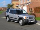
Replacement Discovery 3441 views
|
|

Replacement Discovery 3357 views
|
|

My First Discovery 3 - Replaced by Land Rover736 views
|
|
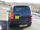
My 1st Discovery 3 - replaced by Land Rover593 views
|
|

46 views
|
|

D3 HEVAC Actuator Replacement26 views
|
|
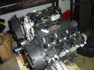
New engine139 viewsReplacement engine, reconditioned unit via Land Rover Australia, circa $6k
|
|
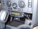
Ashtray panel replacement with ham radio rig.739 views
|
|
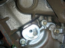
Front Belt Tensioner Mounting118 viewsCam Belt replacement Front
|
|

Thread upload14 viewsImage uploaded in thread 158296
|
|
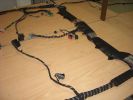
Finished seats area108 viewsThis is a shot of the loom when it was finished from the pass (RHD) door
Both of the seats wiring can be seen, i replaced the conduit on the bottom right and the Yaw rate sensr connector can also be seen in the middle.
|
|
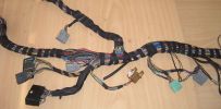
Finished Passenger Kick panel area131 viewsMissing connetor (left most grey) & wiring in, (plastic bracket was broke will use the one in the car) Airbag wires & connector to connector previously cut replaced (on top of grey one to right).
And you can even see the 2 new speaker wires going into the Pass door connector at the very bottom.
|
|

Door Trim and Wing Mirror Removal and Replacement162 views
|
|

Thread upload20 viewsImage uploaded in thread 148456
|
|

Fix stiff gear selector or jumping out of drive into neutral32 viewsThis is a document culled from a topic about a simple fix to teh gearbox selector lever that fixes a problem with jumping out of drive into neutral.
I made the document to give to my local independent and thought it might be useful for others.
Thanks to disco_mikey, EdF and Robbie from the original post whose information and photos made this possible (I take no credit for anything here apart from errors).
|
|

Fix stiff gear selector or jumping out of drive into neutral17 viewsUpdated 19 Dec 2012
This is a document culled from a topic about a simple fix to the gearbox selector lever that fixes a problem with jumping out of drive into neutral.
I made the document to give to my local independent and thought it might be useful for others.
Thanks to disco_mikey, EdF and Robbie from the original post whose information and photos made this possible (I take no credit for anything here apart from errors).
Updated after I did this fix on my own car.
|
|
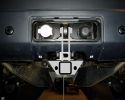
Hayman Reese replacement tow hitch for Australia491 views
|
|

8 views
|
|

57 views
|
|

How To - AMK Suspension Compressor Replacement by Disco_Mikey20 viewsA copy of Disco_Mikey's guide on how to replace AMK Compressor, complete with photos.
|
|

President Johnson II in its current position19 viewsThis CB was installed some years ago and still is at the same location.
However, I'm planning to move it to the head unit area.
As such, I'm looking around to replace my low end head unit with a single DIN radio and the CB on top of it.
|
|

Fireplace 122 views
|
|

Fireplace 221 views
|
|

2037 viewsEverything pulled to bit\'s in order to get cables in for PC Screen etc.
Note the panel with USB and LAN connectors on, this replaces the LR panel with the ash tray in.
|
|
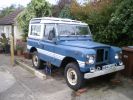
New door tops now fitted. Just needs new fuel tank, replacement footwells and a spot weld or two on the chassis!! 58 views
|
|
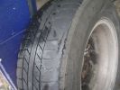
Worn Wrangler153 viewsOn trip to QLD both rear tyres went from slightly worn on inside edges to worn to carcass in just over 1000km. Wheel alignment(thanks to very helpful LR dealer in Maroochydore) and 4 new Continental tyres as no replacement wranglers in Aus.
|
|

Broken Rear Wheel Carrier166 viewsOpposite Lock rear wheel carrier 7 months old, one outback trip. Weld has broken. OL replaced with new improved unit free of charge (has just covered 20000 klm of outback roads without problem)
|
|

Side Light - New24 viewsNew replacement LED sidelight from HIDS
|
|
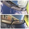
Scuttle and wiper arm replacement19 views
|
|

New Exide AGM battery - Varta silver/calcium battery was replaced under warranty at 79680km.32 views
|
|
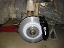
Brakes fitted122 viewsBrakes easy to fir - sensor replacement less so.
|
|

Seat Electrical connector56 views
|
|

T40 Torx Seat Base Bolt48 views
|
|
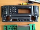
Hk Logic 7 Head Unit Facia replacement9 viewsReplaced facia due to broken buttons
|
|
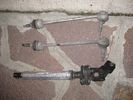
items replaced28 views
|
|
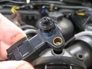
MAP Sensor39 views37,000 miles. EGRs replaced @ 22,000 & 29,000 miles.
|
|
New intercooler85 viewsReplaced intercooler
|
|

Modified Thule 9705 bike carrier50 viewsBar has been moved up above the tow ball and the lower fixing replaced by nuts and bolts.
|
|
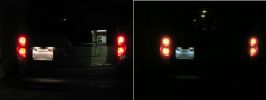
I replaced the incadescent license plate bulbs with new 6-LED bulbs for a cleaner look.420 viewsI was following a 2006 Lexus ES and noticed their license plate bulbs are now using LEDs, so I thought the same thing would look good on the rover.
|
|
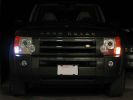
Comparison of the new white LED bulb and the existing incadescent bulb that I replaced.374 views
|
|

Close up of the 6-LED bulb that I used to replace the standard bulb.372 views
|
|
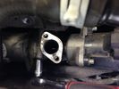
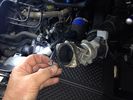
EGR replacement29 viewsUndoing the right hand valve is much easier that the left one.....
|
|
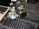
EGR replacement17 viewsThese horrible T30 bolts hold the original onto the EGR cooler. Replaced with nice new M8x16mm bolts
|
|
EGR replacement20 viewsNew one v old one!
|
|
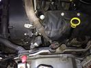
EGR replacement19 viewsLeft side - where the hell is it?
|
|
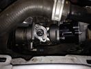
EGR replacement19 viewsNew valve in place. Looking nice and shiny!
|
|
EGR replacement21 viewsThe left EGR valve is tight up against the turbo boost pipe. This make insertion of the long bolts difficult!
|
|
EGR replacement16 viewsBack of left EGR cooler was a swine to replace the clip. Bound it with wire before using pincers to clip together.
|
|
EGR replacement21 viewsNew one in place. Old T30 bolts used on top replacing old rusty ones. Good access here!
|
|
EGR replacement14 viewsWhile doing stuff on the engine. Good idea to clean yer MAF. Brake cleaner and air used to get it clean again
|
|
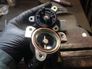
EGR replacement19 viewsOpening the actuator for inspection.
|
|
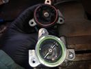
EGR replacement19 viewsOpening up the actuator reveals that all was OK. Even the ball races are OK
|
|
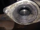
EGR replacement17 viewsOld value with soot cleaned off with wire brush!
|
|

EGR replacement17 viewsCarbon build up under the flange in the sliding shaft
|
|
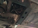
undervody with old intercooler hose9 views6 years and 92,000 kms later, my intercooler hose was about to be replaced
|
|

Interstate Battery Dimension sheet641 viewsThis sheet is hard to find - the sheet is not on the Interstate corporate web site but some dealer web sites display it. The pdf shows most of their available batteries including the H7 and H8 sizes that are the LR North America replacement batteries for the main starting battery. These batteries are of the Land Rover desired "shallow" cycle high discharge current Maintenance Free, (Ca Ca), internal construction, (not AGM, but instead, Wet Flooded Lead Acid with battery "caps" and Ca grid separators).
For the AUX battery , the H6, (BCI Group 48), is probably similar in dimensions to the Varta E12V75N that is popular in Australia. For that battery to fit in the second battery compartment, you must grind out the angled nibs on the inside front bottom of the LR black plastic surround, something I did wish to do and hence installed a Group 40R on a spacer. Alternately, one can choose an Interstate BCI Group 47 which is similar to a DIN H5 for the AUX location. I did this when I had to replace my 40R. No vertical spacer is required and the stock battery tie down bolts and clamp work well.
|
|

Replacement switch from RRS installed on LR3864 viewsThe switch shown is LR part number YUZ500020, the upper rear hatch release switch that is found on the Range Rover Sport.
The switch body is the same switch as on the LR3 except that there is no wiring disconnect on the LR3. Hence when the switch corrodes and requires replacement, the LR solution is to purchase a new handle and license plate light assembly. I instead cut off the old switch and installed a JAE mating connector to the existing wiring and hence just plugged the RRS switch in.
The replacement RRS switch snaps into the same rectangular space in the same manner as the removed LR3 switch, the difference is the JAE male wiring connector.
|
|
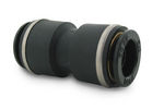
John Guest DOT all plastic fitting717 viewsThis is a picture of the John Guest DOT all plastic union. If you look closely, you can see the DOT imprinted in raised letters on the end of the fitting. This is of a 1/4" connector rather than the 6mm that the 3 requires.
The picture is similar to the air suspension pneumatic fitting union that Land Rover sells as replacement part # STC8580. This is for 6mm OD tubing size. The STC8580 comes with what are called "Collets" at each end that cover up the press to release feature underneath. See the John Guest web site www.johnguest.com under the Pneumatics section and also in Downloads for their catalog for install and remove instructions.
The actual "air brake spec" fitting that Land Rover provides has an interior 4mm OD ferrule that slips inside the 4mm ID of the nominal 6mm tubing. I have not yet been able to obtain the John Guest part number for the LR fitting, only the LR part number. This part number was generated for the RR Classic air systems.
|
|

John Guest (LR part # STC8580) push in straight 6mm tubing to tubing connector730 viewsThis picture is similar to the air suspension pneumatic fitting union that Land Rover sells as replacement part # STC8580. This is a 6mm OD tubing size push in to install straight tubing to tubing fitting. The STC8580 comes with what are called "Collets" at each end that cover up the press to release feature underneath. See the John Guest web site www.johnguest.com under the Pneumatics section and also in Downloads for their catalog for install and remove instructions.
The actual fitting that Land Rover provides has an interior 4mm OD ferrule that slips inside the 4mm ID of the nominal 6mm tubing. Hence the fitting depicted and part number are not actually correct. I have not yet been able to obtain the John Guest part number for the LR fitting.
The fittings that show in this doc are what I call food service fittings rather than transportation or Air Brake fittings. The part LR sells, (STC8580), is the Air Brake type for transportation.
|
|
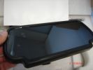
7" tft lcd display to replace rear mirror385 views one of my next projects
|
|

LA501-023 - Technical Bulletin - Child Lock Cam Service Part Replacement Procedure63 views
|
|

Thermostat Housing LR005631538 viewsWhen the time comes to install a new thermostat, consider installing the whole housing instead.
Advantages are the thermostat is correctly installed, (not as simple as it should be); you get all new plastic and that is important, plus a new coolant temperature sensor and also a new heater coolant bypass valve, the secret part no one realizes is also within.
The cost of the whole assembly is not much more than the cost of a factory thermostat and the effort to replace all is not as difficult as it might seem.
|
|

Land Rover LR006482 replacement sounder10 viewsThis is the official Land Rover replacement sounder, part number LR006482 and costs about double the Ford part number sounder. I used the Ford sounder and it sounds the same as the original factory sounder in my 2005 LR3.
|
|
![Filename=lr023964-dunlop-compressor-to-replace-pre-2010-hitachi-only-gb-made-1068977-p[ekm]169x170[ekm].jpg
Filesize=8KB
Dimensions=169x170
Date added=09.Nov 2018 lr023964-dunlop-compressor-to-replace-pre-2010-hitachi-only-gb-made-1068977-p[ekm]169x170[ekm].jpg](albums/userpics/33392/thumb_lr023964-dunlop-compressor-to-replace-pre-2010-hitachi-only-gb-made-1068977-p%5Bekm%5D169x170%5Bekm%5D.jpg)
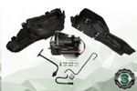
Thread upload3 viewsImage uploaded in new thread
|
|
Thread upload13 viewsImage uploaded in new thread
|
|
![Filename=lr072537-oem-amk-full-compressor-kit-to-replace-hitachi-or-amk-1244723-1-p[ekm]270x224[ekm].jpg
Filesize=15KB
Dimensions=270x224
Date added=26.Feb 2020 lr072537-oem-amk-full-compressor-kit-to-replace-hitachi-or-amk-1244723-1-p[ekm]270x224[ekm].jpg](albums/userpics/33392/thumb_lr072537-oem-amk-full-compressor-kit-to-replace-hitachi-or-amk-1244723-1-p%5Bekm%5D270x224%5Bekm%5D.jpg)
Thread upload12 viewsImage uploaded in new thread
|
|
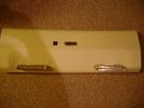
Boot lighting panel, finish side up 310 viewsThe above jpg shows the two 15 LED light assemblies as well as the SPST rocker switch mounted beside the W5W Land Rover supplied light.
The reality is that with the recent development of LED lighting that can replace a W5W T10 bulb, one can almost achieve the same results just by installing a LED bulb within the factory light.
|
|
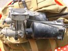
Compressor Air Drier 2044 viewsA view of the air drier - the black round thing to the right of the actual compressor cylinder head.
The general feeling is that the air dryer is responsible for most of the compressor problems now and that replacement of either the assembly or just the beads inside will probably revive one's compressor. In reality, the beads may have for the most part broken down and turned to dust plugging the internal filters. Hence replacement of the complete dryer unit has some merit.
The part number for the dryer assemble complete with the desiccant is VUB504700.
|
|
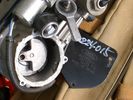
Compressor Con Rod Broken 1753 viewsThe model number of this compressor is RQG500060; the model number of my replacement compressor was LR015303, the unit that was apparently being installed on the D4 vehicles as of Spring 2010. As of Fall 2011, the new replacement part number is LR023964, the same as in the 4's.
Note the number hand written on the black plate. All the compressors seem to have some number hand written on them - hand built I presume, and every unit perhaps evolving a bit differently as LR struggles to build a compressor that will last. I guess Hitachi, (the manufacturer), should be given credit for that.
|
|
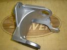
Replacement Bracket, LR part # RQU500064 for Air Compressor1026 viewsThis is a jpg of an aluminum replacement air compressor bracket, Land Rover part number RQU500064. The three rubber noise isolators are to be removed from the old bracket and inserted in the new bracket.
|
|

LR3 Denso Alternator YLE500390 pulley view819 viewsNote the DENSO sticker on the side. Denso calls their nominal 150 amp 12 Volt alternator an SC2 design. SC means Segment Conductor which apparently increase the winding density of the stator coil, hence yielding a physically smaller lighter alternator for a given output. I presume the 2 means the second try at getting it right. A Denso part number is 4280003690 for the alternator, (there are others, as below).
Rotation is clockwise and the 54mm diameter pulley has 6 grooves (PV6x54). Count the pulley grooves on both the one you remove and your new one - some replacement alternators seem to ship with 5 or 7 grooves so you might be swapping pulleys.
A previous LR part number was YLE500190 for the older variation of the newer YLE500390 unit.
An additional part number for a factory rebuilt is Nippon Denso 210-0569 for the petrol V8 alternator. Other Nippon Denso numbers include 104210-3690 and 104210-3691. The Lester number is 11206 which relates to another Denso number of 290-5287. WAI uses 11206N.
From 2006 to 2009, the internal regulator is a Transpo IN6349 and of the B circuit type if it can be said that applies to PWM, (Pulse Width Modulated), regulators.
The "regulator" inside the alternator is therefore really not a regulator in the old sense of the term but instead an instruction receiver from the ECM that translates Pulse Width Modulated (PWM) signals into a form that the alternator understands – digital like signals from the Engine Control Module(ECM) into analogue like signals that the windings understand.
|
|

Power fold pivot less mirror38 views
|
|

Butchery of replacement mirror42 viewsI had to bend the retainng sleeve (bottom right) to be able to split the outer arm from the pivot.
|
|

Dry fit - Mirror shell and support arm43 views
|
|

Outer Mirror Shell and support arm in place45 views
|
|

Mirror parts42 views
|
|

Mirror shell replaced - notice self tapping screws52 viewsMirror shell replaced - notice self tapping screws to replace "plastic rivet heads" and also washers on inner screw to prevent screw piercing mirror housing due to short hole.
|
|

Finished Job - Mirror shell replacement44 views
|
|

Mirror - power fold pivot and pan/tilt/heat wiring42 views
|
|

Door mirror - outer support arm43 views
|
|

Mirror pan and tilt mechanism 42 views
|
|

Power and Sense connector on door mirror40 views
|
|

Mirror pivot with outer support removed36 views
|
|

LTB00051 - Technical Bulletin - Starter Motor Solenoid Replacement90 views
|
|

LTB00222 - Technical Bulletin - Steering Gear Tie Rod Tie Rod End Diagnostic Procedure and Required Replacement Parts Information127 views
|
|

LTB00269 - Technical Bulletin - Air Suspension System - Compressor Delivery Valve and Drier Replacement Software Update2926 views
|
|

LTB00331 - Technical Bulletin - Air Suspension Compressor and Relay Replacement224 views
|
|

34 views
|
|
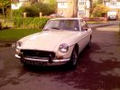
This replaces the Mini Cooper S587 views
|
|
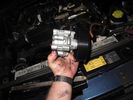
replacement pump69 views
|
|

Mirror Glass Replacement54 viewsMirror Glass Replacement PDF
|
|

Front replacement coil spring - King Springs127 views
|
|

Rear replacement coil spring - King Springs116 views
|
|
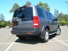
After replacement heavy duty coil springs fitted129 viewsReplacement King Spring coils fitted 22 February 2008. Oem shocks retained.
Wheel arch measurements (note that the old springs - weighing perhaps 30kg - were sitting in the boot when the "after" measurements were taken):-
FRONT
Before - 33" (84cm)
After - 35¼" (89.5cm)
REAR
Before - 33" (84cm)
After - 34¼" (86.7cm)
|
|
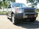
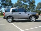
After replacement heavy duty coil springs fitted188 viewsReplacement King Spring coils fitted 22 February 2008. Oem shocks retained.
Wheel arch measurements (note that the old springs - weighing perhaps 30kg - were sitting in the boot when the "after" measurements were taken):-
FRONT
Before - 33" (84cm)
After - 35¼" (89.5cm)
REAR
Before - 33" (84cm)
After - 34¼" (86.7cm)
|
|

From wheel arch after replacement heavy duty coil springs fitted135 viewsAfter replacement heavy duty coil King Spring coils fitted 22 February 2008. Oem shocks retained.
Wheel arch measurements
FRONT
Before - 33" (84cm)
After - 35¼" (89.5cm)
|
|

Rear wheel arch measurement after replacement heavy duty coil springs fitted146 viewsAfter replacement heavy duty King Spring coils fitted 22 February 2008. Oem shocks retained.
Wheel arch measurements (note that the old springs - weighing perhaps 30kg - were sitting in the boot when the "after" measurements were taken):-
REAR
Before - 33" (84cm)
After - 34¼" (86.7cm)
|
|
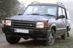
First Discovery10 viewsA battered-to-death-by-farmers and then brought-back-from-the-dead 300TDi Disco. When first seen the driver's seat was a plastic crate. Resprayed in Eastnor Green with replacement front seats and steering column controls that had been chewed off by farmer's dog. In many respects my best Land Rover buy ever!
|
|

3 Button Key Fob Case46 viewsReplacement case for 3 button Key Fob (Disco 3 & RRS 2005-2009)
|
|
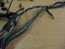
All wires done92 viewsAll the cut wires have been replaced now, almost time for the loom tape.
|
|
Thread upload29 viewsImage uploaded in new thread
|
|
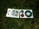
Rebuild Kit1032 viewsReplacement custom Crown Wheel & Pinion, upgraded seals, OE bearings, replacement needle bearings.https://www.facebook.com/DifferentialPartsUS
|
|
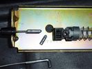
This is the broken one in situ, and the replacement part below97 views
|
|
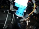
brake light switch3663 viewscommon failure, replace with newer one marked fomoco
|
|
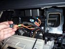
original MOST cable123 viewsreplace the short cable from Radio to Nav display with part of the additional MOST loom (YMQ502470)
|
|
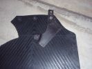
Brace, for additional support, from OEM's fixed to replacement mud flaps53 views
|
|

the replacement rubber piece189 views
|
|

Intercooler tube - split32 viewsLoss of power, black smoke on kick-down?
Don't let them replace your turbo!
|
|

Instructions & advise on replacing the pollen filer277 views
|
|

Pollen Filter37 views
|
|

Pollen Filter Replacement in HVAC System506 viewsThe attached single page doc includes links to pictures of the procedure to replace the "air" filter behind the passenger side glove box related to the Heater AC system.
Part numbers are provided for both Land Rover and Mann filters, both the activated carbon type and the non charcoal filters.
|
|
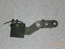
Radio Noise Suppression Capacitor NNW502820699 viewsThis is the radio noise suppression capacitor, part number LR020488 (previous NNW502820), that is mounted underneath and near the transmission. It is powered by fuse 10 amp F30E in the engine compartment. If F30E blows, (the fuse that also powers the transmission ECU), the problem is probably caused by the failed capacitor, not the ECU. A quick fix is just to disconnect the capacitor and replace the fuse as nothing bad seems to immediately result.
The above radio noise capacitor is not to be confused with LR004160, the ignition noise capacitor which is located under the black plastic engine cover on the right hand side above the air intake towards the rear of the engine.
The ignition capacitor is held on with a single 8mm bolt and a three wire electrical connector. Replacing the ignition capacitor as a routine maintenance prevention action at 100,000 miles, 160,000 km), has merit. It is a do it yourself kind of thing and easier to get at than the radio capacitor underneath.
|
|
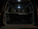
With just normal interior lights (but HID\'s High Intensity LED Replacement)78 views
|
|
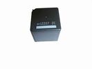
Front Blower R16 relay, part number YWB500060482 viewsThis is the front fan relay located in the engine compartment fuse box. It should be replaced and installed new when a new fan is installed.
|
|
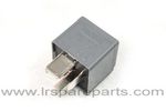
Air Compressor 70 amp replacement relay1393 viewsThere is a software update, 09 April 2010, LTB00270, for the compressor which reduces the shut down pressure to about 205 psig (14 bar). The update is usually done when changing to a new compressor and also includes replacing the R7 relay in the engine compartment fuse box, 07 DEC 2010 LTB00331.
The newer grey case coloured relay, part # YWB500220, shows to be rated at 70 amps, (the relay, not the compressor), however the previous black case coloured relay also indicates 70 amps.
Both the new and replaced relay show on their wiring diagrams to have a parallel voltage spike resistor, (probably 560 ohms), across the coil terminals, #1 and #2. This means one does not just replace the relay with any four prong 70 amp ISO sized relay that one happens upon.
One presumes the grey relay is either upgraded or just being installed for good measure. The relay is common on Ford Fiesta for the seat heater relay, Ford part number 5M5T 14B 192 EA; also Volvo, part number 30765034. The Tyco part number moulded on the grey body is V23136-J4-X62.
|
|

35 views
|
|

Replacing the blower motor578 viewsThis is a 6 page pdf with regards to replacing the HVAC blower fan and the associated fan speed module in a LHD North America spec LR3. The fan can be replaced from below and it is not necessary to pull the dash apart.
|
|
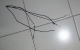
Discarded cut wires80 viewsThese are Earth wires that have been completely replaced.
|
|

Page 1-41045 views
|
|

Page 5 - 8818 views
|
|

Page 9 - 12771 views
|
|
Replacement Smoke34 views
|
|
Replacement Smoke30 views
|
|
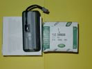
Upper Hatch Release Switch LR Part Number YUZ500020676 viewsThis is the Range Rover Sport switch, Land Rover part number YUZ500020, as it comes out of the box. Note the JAE, (Japanese Aviation Electronics), male wiring connector installed on the end of the power lead.
The rubber cover of the switch is sealed to the plastic body of the switch whereas in the previous switch design, there was no sealing. Also the replaced switch was hard wired into the same harness as the license plate lights - no JAE connector in other words.
|
|

Tailgate Actuator DIY.99 viewsIf your stuck with the problem of the boot not opening and can't wait for the replacement, here's the DIY.
|
|
![Filename=Technical Service Bulletin SB034 SB036 Vehicle Enhancement Program[1].pdf
Filesize=959KB
Dimensions=0x0
Date added=17.Jun 2010 Technical Service Bulletin SB034 SB036 Vehicle Enhancement Program[1].pdf](images/thumb_pdf.jpg)
Technical Service Bulletin SB034 SB036 Vehicle Enhancement Program2390 viewsOn page 6 and following are the Land Rover service bulletin instructions as to how to install delivery valve and exhaust valve repair kit JPO500010; also a list of previous compressor model numbers as related to the 3. The new delivery valve is easy to install, the exhaust, not so easy. Note that this in not the more recent TSB that reduced the operating pressure of the compressor via a software fix and also recommended replacement of the air compressor 70 amp relay. See the F35 album near the bottom for the relay material.
|
|
Radio Noise Filter Transmission Electronic Control Unit915 viewsThe jpg shows part number LR020488, a noise suppression capacitor located underneath on a bracket on the right side of the transmission forward of the selector shaft lever. The suppressor is connected to the transmission wiring harness and prevents solenoid operating noise affecting the audio system.
Failure of the capacitor is most often discovered as a result of either black smoke from below and or the blowing of 10 amp fuse F30E located in the engine compartment fuse box. This fuse protects the power circuit to the Transmission Engine Control Unit. When the fuse blows, the engine will still run however you have no gears, hence movement of the 3 is inhibited.
Anything over eight years in service is considered good capacitor life. If the capacitor does fail and fuse 30 blows, a quick fix is just to disconnect the capacitor and replace the fuse.
The capacitor might be missed by the DOT/FCC but the 3 does not seem to mind. With the filter disconnected, solenoid noise might be heard on some radio stations but at least the 3 would be in motion.
|
|

Vehicle Maintenance Log for LR3/4 D3/4 or other1135 viewsThis is a Excel file that you can download and then modify to suit. It is very simple, but allows me to keep track of most maintenance and fixes etc on my LR3. All columns and rows and boxes can be edited.
I did not erase any data in the various boxes so you could see how I am using it - again not very fancy but it works for me. Under the brakes column, one will see f6 r5 which is how I keep track of the condition of the brake pads. The dealer records the pad thickness at each oil change so that is where the numbers come from.
f is for Front Pads, 6 is for 6mm; r is for Rear pads, 5 is for 5 mm. New pads are about 10 mm; replacement is at 3 mm or less. The amber coloured brake wear dash warning light should come on at about 2 mm.
|
|
Thread upload11 viewsImage uploaded in thread 207493
|
|

New Wiring Overlaid98 viewsSport loom gives me length info to position replacement connector and its wiring in. Her you can see the new wires lying over the top of the cut of ones.
|
|

ZF 6HP26 and 6HP28 Comparison plus oil pan and filter replacement options963 viewsThis is a 66 page ZF produced pdf that provides comparisons between the various ZF transmissions; also instructions regarding maintenance of the Mechatronic unit, the round seal; the various metal and plastic pans available as well as tips regarding changing the oil.
This ZF pdf has a number of colour pictures and part numbers within as well.
|
|

Electrical Connector Sleeve Replacement ZF 6HP26973 viewsThis 3 page pdf with pictures shows how to replace the sleeve that holds the multipin electrical connector that passes thru the transmission body to the Mechatronic unit.
The install of the sleeve is more difficult than the removal in that one must not rotate the sleeve as damage to the internal pins can result. The pan must be first removed to both remove and install the sleeve.
|
|

Mechatronic Sleeve Removal and Install Instructions1058 viewsThis 3 page pdf with pictures shows how to remove and install the Mechatronic sleeve that tends to leak tranny oil after about ten years. Even if not leaking, replacement when doing a pan/filter change at the ten year mark is suggested.
Note the 3mm or less requirement when sleeve installation is completed; also that rotation of the sleeve during the install procedure can do damage to some internal pins - hence do not rotate the sleeve when trying to insert it or in getting it to lock in place - not so easy it seems.
|
|

Mechatronic Replacement Hints plus drains for steel and plastic pans1111 viewsThis 22 page pdf shows colour views of the Mechatronic unit as well as good illustrations of the drain and fill ports in both the plastic, page 17, and steel pans, page 18.
Page 8 details the replacement of the sealing sleeve where the electric wire feed thru the case into the Mechatronic unit. The seal is normally replaced when a new pan is installed as the seal is a known leakage point.
|
|

45 viewsthe radio is going to be taken out and replaced with a double in dvd/gps/tv
and the sat nav cubb is going to have a custom made iphone holder inside of it (if all goes to plan anyway)
ill upload pictures when its done
|
|
|
|