| Search results - "radio" |
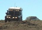
110 at Carinya Escapes ,Flinders ranges295 viewsDefender 110 Extreme,Long Range fuel tank,under floor water tanks, HF radio,GKN Overdrive,Swingaway Spare Carrier,70 litre Freezer,30 litre Fridge,Roof top Camper,Cruise Control,
|
|

Radio location539 viewsMy remote head UHF CB mounted on the front of the ashtray, ham HF/VHF/UHF remote head radio mounted on a block in the coin tray and my GPS on a turned wooden block in the cup holder. Both radios are under tha driver and passenger seat and the antenna for the GPS is suction mounted inside the windscreen.
|
|
RH Side Ctr Csle46 views
|
|

34 views
|
|
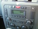
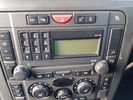
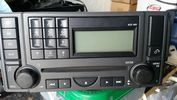
Base Spec Radio/CD2469 views
|
|
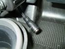
The 3.5mm socket for ipod etc.3595 views
|
|
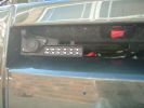
Socket for control lead and switch for radio-remote moved from solenoid pack to bumper1037 views
|
|

265 viewsSmooth leather steering wheel with cruise and Radio switches
|
|
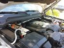
Traxide USI-160 Install515 viewsOverview picture of Traxide USI-160 upgrade install. This was an upgrade from the SC80 which performed flawlessly. The USI-160 had two relays and can deliver more amperage. As a result, the wiring was upgraded to 4/0 Welding Cable (warn) and heat shielding was added. The unit performs flawlessly to support 2 HAM Radios, Fridge, etc. Like me https://www.facebook.com/DifferentialPartsUS
|
|

Embroidered T-shirt97 viewsEmbroidered in Khathmandu in a shop, from any design, by hand, overnight.
(9N1SC is a radio call-sign)
|
|
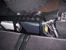
HF radio on RH side Inverter on LH. Frame is fitted behind second row of seats. (I have removed 3rd row as they will never be used)310 views
|
|
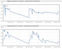
On Solar245 viewsOn Solar, Snomaster Fridge, Ham Radio and 100W Grape Solar panel, Deka 9A94R Intimidator AGM. I can supply the Stainless Snowmaster Fridges. Other components if you need help.
|
|
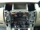
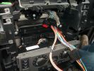
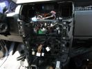
3 Radio etc removed ready to remove dash pocket85 views
|
|

Alternator and Regulator Wiring Diagrams, TDV6 and petrol V8 and V61989 viewsThis is a three page pdf that shows the alternator and regulator wiring for the petrol V6, petrol V8 and TDV6. The pdf can be either printed or by right clicking on the displayed pdf, rotated as required for viewing.
Of interest is that the regulator gets its instructions primarily from the Engine Control Module (ECM) and only secondarily from the vehicles electrical buss. The conductor from the battery thru the 5 amp fuse F20E is to provide initial power to excite the alternator at startup and then secondarily, to instruct it if the PWM signals were not available. Primary instructions to and from the ECM are thru the two other conductors via a digital like Pulse Width Modulated (PWM) signal.
If F20E, the 5 amp engine compartment fuse box fuse is blown, the red alternator light on the dash will be illuminated. This means that the alternator could be OK, but if the F20E fuse is blown, no electricity will be generated. Hence check the F20E fuse if you get a red ALT light or some indication of the alternator not working.
Regarding operation of the red ALT light on the dash, it is not the regulator within the alternator that tells the red light to illuminate, or not, but instead the ECM. This is the reason the red light does not function in the same manner as with older vehicles. With the 3, sometimes you have illumination and sometimes not depending upon what the ECM is thinking. What this means is that you can have an alternator that is failing but the red light does not illuminate as the ECM is compensating for reduced alternator output - maybe by draining the battery and or cutting back on vehicle electrical loads such as shutting off or cycling the radio amplifier or heated seats.
|
|

Entertainment System Wiring Diagrams2331 viewsThe 12 page pdf has the wiring diagrams for the low and high line "radio" and various components such as the amplifier, phone modules,NAV display, antennas and satellite radio and TV.
|
|
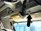
6 Radio diversity Amplifier59 views
|
|
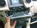
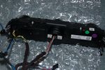
FRONTALE RADIO SMONTATO120 views
|
|
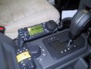
Ham Radio454 viewsThe remote head of the Icom IC706 mounted on a block of wood shaped to fit the coin holder. This is an HF, VHF and UHV transceiver.
|
|
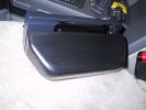
Ham Radio448 viewsThe remote head of an Icom IC706 was mounted on a piece of wood shaped to fit into the coin holder. This is quite a tight fit and does not shake loose. The radio is mounted under the driver seat.
|
|

Land Rover Aerial Fin images for both Glass and Metal Roof Disco3 / LR3863 viewsAs well as the two different fins, this pdf also shows the plastic blanking plate for glass roof vehicles where no fin is installed.
The glass roof fin is secured by two security screws from the top into a plastic frangible glue on gasket. The hope is that when struck, the fin will shear off and not crack the glass roof. Re the metal roof design, the fin is secured from underneath via two nuts.
The pdf also shows the various electrical bits related to the antennas. In the UK, the fin would house not only a cell phone antenna but the TV and satellite radio antenna electronics as well; in the States, the Sirius sat radio antenna and a G type cell phone antenna if the phone kit was installed would reside within the fin. The SAT NAV GPS antenna is located within the High Mount Brake Light plastic mounted to the upper rear hatch.
|
|

Amp Drawing53 viewsThis is how many amps my vehicle was using when the ign in possision II. Lights where off, radio off,hvac off Crazy?
|
|
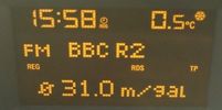
Astra 1.6 fuel consumption29 viewsFuel consumption of a 1.6 petrol Astra after a return trip from Aberdeen to Peterhead.
And yes I know i am sad listening to radio 2, but it was the only station I could understand up there.
|
|

158 views
|
|

Thread upload13 viewsImage uploaded in thread 130027
|
|
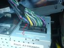
base radio aux connections665 views
|
|
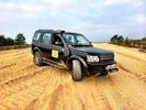
Radio duty at Bovington camp for the BCCC115 views
|
|
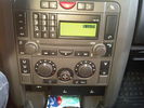
radio dash for BT project68 views
|
|
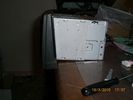
This show that the angel of the radio body is diffrent from the original, hence shall some plasic be removed - I used a dremmel and removed 7 mm of the horizontal bar inside 160 views
|
|
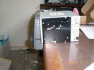
This shows the standard radio body angle161 views
|
|
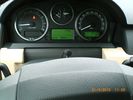
I placed the mic for the hand free at the steering colum - easy install and seems to work fine139 views
|
|
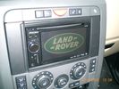
Job done - after adding nice start screen :-)237 viewsPinoeer AVIC-F910BT installation
|
|
![Filename=Cura_Ponte radio_Faggeta 12-2008 21 - 28 dic 2008 - 21 [1024x768].JPG
Filesize=113KB
Dimensions=1024x768
Date added=06.Jan 2009 Cura_Ponte radio_Faggeta 12-2008 21 - 28 dic 2008 - 21 [1024x768].JPG](albums/userpics/12685/thumb_Cura_Ponte%20radio_Faggeta%2012-2008%2021%20-%2028%20dic%202008%20-%2021%20%5B1024x768%5D.JPG)
My Camera moount 3113 views
|
|
![Filename=Cura_Ponte radio_Faggeta 12-2008 22 - 28 dic 2008 - 22_m [1024x768].jpg
Filesize=321KB
Dimensions=576x768
Date added=06.Jan 2009 Cura_Ponte radio_Faggeta 12-2008 22 - 28 dic 2008 - 22_m [1024x768].jpg](albums/userpics/12685/thumb_Cura_Ponte%20radio_Faggeta%2012-2008%2022%20-%2028%20dic%202008%20-%2022_m%20%5B1024x768%5D.jpg)
My Camera moount 292 viewsIl supporto per la fotocamera digitale
|
|
![Filename=Cura_Ponte radio_Faggeta 12-2008 24 - 28 dic 2008 - 24 [1280x768].JPG
Filesize=121KB
Dimensions=1024x768
Date added=06.Jan 2009 Cura_Ponte radio_Faggeta 12-2008 24 - 28 dic 2008 - 24 [1280x768].JPG](albums/userpics/12685/thumb_Cura_Ponte%20radio_Faggeta%2012-2008%2024%20-%2028%20dic%202008%20-%2024%20%5B1280x768%5D.JPG)
My Camera moount 1101 viewsIl supporto per la fotocamera digitale
|
|
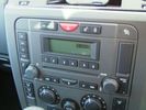
Thread upload1 viewsImage uploaded in thread 146346
|
|
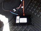
D4 Bluetooth AH42 10F845 AA module connected to 12VDC and MOST1210 viewsThis jpg shows the MOST bus connected to the AH42 10F845 AA module used in the D4 as well as +12VDC power from F58P connected. The power is split with a Y harness as the IHU (radio) for some reason required +12VDC power to the C2115-10 "mute" pin to keep the radio/CD audio from muting all the time.
With power on the pin, the radio audio does mute as it should when the cell phone rings and the hands free connects. The brown conductor feeds to C2115-10 and the blue to the module.
The module tucks up and hides behind the grey plastic section covering the forward portion of the passenger side tranny hump for left hand drive vehicles; for RHD, it would be located on the left side.
The pairing code is 2121 with this setup and not 1234 or 0000.
|
|

Thread upload19 viewsImage uploaded in thread 121278
|
|

D4 radio surround4 views
|
|
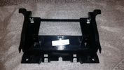
D4 radio surround rear3 views
|
|

Older Cell Phone handset holder operation and components849 viewsThis 8 page pdf explains the operation of the older Cell phone handset holder and shows the various components as related to the radio and phone buttons etc.
|
|

415-03 Audio System - Low and High Line Radios934 viewsThis 8 page pdf shows both the low and high line radios and their various components.
|
|

415-02 Antenna systems for AM/FM, Satellite, GPS and TV systems542 viewsThis is a 5 page pdf related to the antenna systems for the AM/FM radio, Satellite radio, the GPS/NAV and the optional TV.
|
|

419-08 Low and High line radio systems components and operation838 viewsThis 15 page pdf displays the radio components including pinouts for both the low and high line head units and the two Harman Kardon amplifiers including the Logic 7 amp. The steering wheel controls for both the radio and phone system are also outlined along with mention of the Sirius satellite radio feature.
|
|
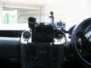
369 viewsHome made console, GPS in clip off mount, 29Mg radio,dual battery moniter,long rang tank gauge & elecric switches.A clip out removable console with no screws.PS also a camera mount.
|
|

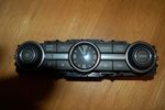
Stainless Steel Radio & Heater Control Covers110 views
|
|
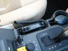
UHF Radio488 viewsGME TX3400 head mounted in console
|
|

Thread upload6 viewsImage uploaded in thread 91468
|
|
Thread upload7 viewsImage uploaded in thread 91468
|
|
Thread upload4 viewsImage uploaded in new thread
|
|

UHF Radio installed21 views
|
|

UHF Radio head22 views
|
|
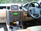
DAsh with PC, Ham radio rig, Nokia display, sat nav,1035 views
|
|
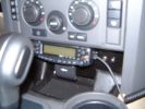
Ashtray panel replacement with ham radio rig.739 views
|
|
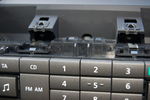
Top of Radio116 views
|
|
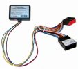
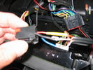
the blackbox to make it play during drive97 viewsplaced on the left side of the radio
|
|
88 viewsdvd plug inthe back of the radio
|
|
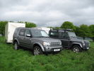
Out On Field day91 viewsOut on a Amateur Radio field day. Full trailer and landrover load space with equipment. Defender also full!!
|
|
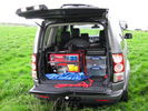
Disco 4 load area full 107 viewsOut on a Amateur Radio field day near Banbury. Wet and Windy weekend!!
|
|
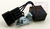
Thread upload187 viewsImage uploaded in thread 44647
|
|

Alternate Buttons D4 Radio22 views
|
|

President Johnson II in its current position19 viewsThis CB was installed some years ago and still is at the same location.
However, I'm planning to move it to the head unit area.
As such, I'm looking around to replace my low end head unit with a single DIN radio and the CB on top of it.
|
|
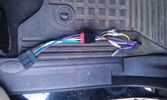
56 viewsThe OEM 2 ISO harness. Notice the red and yellow, which are important for my radio. Not having the red connected simply didn't activate the radio (so I wonder what the radio does with the permanent 12V)
|
|

64 viewsAdded a lead coming from the 12V outlet in the front console. That one is activated only when the ignition is set to I. So that's actually what is referred to as accessories in the manual of the radio. The OEM connector for the head unit did not have any similar lead. The yellow is permanent 12V, the red (on the converting OEM 2 ISO) is the accessories 12V.
|
|

35 viewsThe facia had some bits sticking out which fit quite nicely with the supplied double DIN support. As I was going to use the DIN supports supplied with either the radio and the CB, I needed to remove those bits sticking out. They made the DIN support bend as well.
|
|
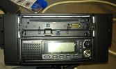
75 viewsThe Pioneer DEH X9500BT on top with the CB President Johnson II beneath.
I had to cut the bottom part of the CB 2 DIN conversion kit in order to have the supplied cover with the facia in place as it should.
I eventually didn't use the supplied facia of the radio as it's bottom part was covered by the CB's kit.
|
|

60 viewsNormal usage, only the radio's on and controlling the connected iPod.
|
|

67 viewsRadio and CB activated. Tried to have the radio's colour similar to the CB.
|
|

FT-8900 radio body mount97 viewsYaesu FT-8900 mounted on access door. Multi-way socket on front.
|
|
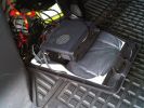
FT-8900 mount97 viewsFt-8900 radio body mounted in luggage area
|
|

Dash View 0194 viewsShows remote radio head (FT-8900), fist microphone and sat nav. Mic is fixed using Velcro...
|
|
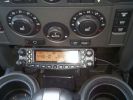
FT-8900 radio head mount96 viewsFT-8900 radio head mounted on ashtray. Extension speaker below.
|
|
848 viewsChecking the radio loom to see what does what
|
|
855 viewsFitting Nokia 810 Phone kit
|
|
1633 viewspicture showing the location of the "Lodar" radio winch remote control box.
|
|
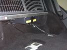
HF radio under rear floor (5 seater)171 views
|
|
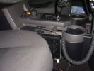
UHF radio beside drivers seat167 views
|
|

UHF radio and handset152 views
|
|
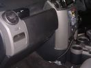
Speaker (above glove box) and Handset for HF Radio153 views
|
|
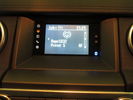
D4 Lowest Grade Radio - Screen Closeup72 viewsThe monochrome screen with colour-lit icons on the left to indicate source, and bluetooth icon on the right to indicate connectivity. There are also two hardware buttons for hour/minute clock setting.
|
|
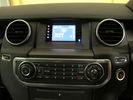
D4 Lowest Grade Radio - Wide Angle76 viewsThe CD player is at the bottom of the picture, the control buttons in the middle, and at the top is the screen with colour-lit icons on the left to indicate source, and bluetooth icon on the right to indicate connectivity. There are also two hardware buttons for hour/minute clock setting.
|
|
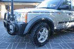
771 viewsHF Radio antenna/Cooper stt tyres
|
|
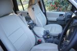
766 viewsTemporary plcement of radios until overhead console is available
|
|

SatNav, screen and HAM radio fit115 views
|
|
Radio amp on right hand side69 views
|
|
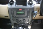
GME TX3400 CB radio246 views
|
|
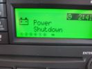
faulty radio ..shutting down before the required voltage160 views
|
|
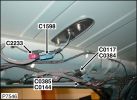
LR Antenna601 viewsRed connector = GSM
Blue connector = Satellite Radio
|
|

LR Electric Trailer Brake C2590 Female Connector606 viewsThis female connector, C2590, located up above and near the brake pedal is for the Trailer Electric Brake Controller hookup.
The Black wire in the bottom right is pin #3, the ground. The Blue wire to the left is pin #6, the Trailer Brake Controller output going to the rear trailer socket.
The White #4 wire is the 30 amp fusible link, (Link 6E in the engine compartment junction box), for the Brake Controller 12VDC power feed from the battery. Note that this would make a pretty good power source for CB radios and the like if no electric trailer brakes were required.
Pin #5 is a Green wire from the stop lamp switch, (the control input for the Brake Controller).
This plug is standard on all NAS (LR3) vehicles, but unlikely to be found on the D3 spec units.
|
|

LR3 Air Conditioner Drain Tubes behind centre console2131 viewsThis shows the two air conditioner drain tubes located left and right under the radio stack.
The tube on the left side, (steering wheel side, LHD), disattached itself and the carpet on the floor under the gas pedal etc became soaked. I think rain water from outside that comes in the outside cowl vents also exits via the tubes as I first noticed the carpet was wet after parking outside during a big rain storm.
It was relatively easy to slide up and reattach the rubber hose that runs from the rectangular shaped plastic discharge hole(s) of the heater "pan" down along the transmission hump area and thru the floor pan. There is a hose on each side of the transmission hump, but only one hose had let go on my 3. The rubber hoses just slide over the rectangular plastic openings of the two heater housing drain outlets.
To get at each drain hose, remove the vertical sort of triangle carpeted piece below each side of the radio stack. The triangles of carpet will just pull away as each is held on with those metal U clips Land Rover so likes. Dislodge each triangle at least sufficiently to get ones hand in to slide the rubber hose back on.
You will rarely see AC water on the ground as the front drains pour onto a metal underside protection skid plate and the rear drain onto the top of the left rear muffler.
|
|

Carpet Panel Removed showing Bass Speaker and Dust Shield 1733 viewsSomething is wrong with the orientation, however this shows what you see when the carpet is removed.
The dust shield, (under which the actuator is located), in the picture is as yet uncut. The white bit is the underside of the plastic lower lift gate carpeted cover panel.
The round thing is the woofer speaker for the Harmon Kardon radio. When the radio is working, one can see the speaker moving, but not much bass sound actually seems to emanate from the speaker.
|
|
![Filename=LR3_Radio_Removal[1].pdf
Filesize=190KB
Dimensions=320x240
Date added=04.Feb 2014 LR3_Radio_Removal[1].pdf](images/thumb_pdf.jpg)
Radio Removal from Radio Stack571 viewsThis shows how to remove the radio from the stack. Basically you remove the H surround first and then at least loosen all the Torx 20 screws left and right sides from the top down starting at the narrow unit that the four way flasher/locking buttons are mounted on.
The units kind of interlock, hence some movement of each is required to remove the radio by itself. I find it best to take out the four way flasher/locking buttons assembly first as that allows access to the fibre optic cable connector into the back of the radio head without too much tugging.
|
|

SDARS Satellite radio operating instructions 352 viewsThis is a 14 page pdf portion from the Owners Handbook with regard to operation of the satellite radio system operating on the Sirius channels.
|
|

Thread upload6 viewsImage uploaded in thread 155707
|
|
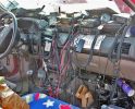
Typical XTC install128 views
|
|
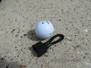
MOST fiber optic loop tool468 viewsThe looping tool in the jpg uses the Land Rover type plastic fiber optic cable with both ends feeding back into a female fiber optic connector that mates with the male fiber optic connectors on the Land Rover system.
The purpose of the loop is to allow one to disconnect MOST connected items such the BlueTooth module or the HK amplifier but allow the MOST system to still transmit signal from the head unit as the circuit would remain closed and hence complete. Of course with the Bluetooth module disconnected, there would be no Bluetooth available, however the radio and NAV would still function.
The looping tool allows one to troubleshoot the system by removing one component at at time from the MOST loop. In other words, what might appear to be a radio problem could be a Bluetooth problem - that sort of thing.
|
|
Thread upload2 viewsImage uploaded in thread 146346
|
|

Thread upload4 viewsImage uploaded in thread 204507
|
|
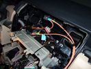
original MOST cable123 viewsreplace the short cable from Radio to Nav display with part of the additional MOST loom (YMQ502470)
|
|
additional most cable added to radio & nav display 110 views
|
|
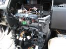
280 viewsHere is the center console with the support pulled away. You can see the wiring for the HD and XM radios working their way through the console and over to the lower glove box.
|
|
278 viewsA mess of cables. You can see the HD Radio antenna adapter coming out into the slot for the IHU. You can also see, if you look very closely, the original diversity antenna connector plugged into another adapter to go down to the HD radio unit.
|
|
Radio Back89 views
|
|

259 views
|
|
Radio Front89 views
|
|

radio wiring diagrams84 views
|
|
Thread upload1 viewsImage uploaded in new thread
|
|
117 views
|
|

19 views
|
|
10 views
|
|

Thread upload37 viewsImage uploaded in new thread
|
|

Thread upload6 viewsImage uploaded in new thread
|
|

Thread upload6 viewsImage uploaded in thread 152961
|
|

Thread upload1 viewsImage uploaded in new thread
|
|

Thread upload1 viewsImage uploaded in thread 89442
|
|

radio aeriels83 views
|
|

Thread upload9 viewsImage uploaded in new thread
|
|

1 radio back78 views
|
|

2radios79 views
|
|

139 views
|
|
144 views
|
|

Thread upload17 viewsImage uploaded in new thread
|
|

Thread upload0 viewsImage uploaded in thread 185939
|
|
Thread upload0 viewsImage uploaded in new thread
|
|

Thread upload1 viewsImage uploaded in new thread
|
|
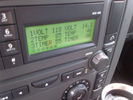
Voltage Display Page Radio Head Unit 118 14.2840 viewsThis shows the voltage/temperature/timer display page within the 6CD-465 radio head. There is a second file within this album, a doc file, that outlines the procedure to access the diagnostics.
The 14.1 volts number was the approximate vehicle system voltage with the engine running; the 118 number infers 11.8 volts which is the low power infotainment system shutdown cutoff voltage. The factory default setting is 135 or about 13.5 volts. By holding the keypad 1 button down, the 3 digit volts numbers will decrease 001 at a time until the keypad 1 button is released. Decreasing the number from 135 to some lower number should increase the time the system will remain on with the engine off.
The TEMP numbers refer to Fuel Burning Heater, (FBH), temperature values. 85 is apparently a high limit and 46 was the number when the jpg was taken. This number varies and given that there is no diesel fueled FBH in our NAS petrol engine vehicles, what the value refers to is unclear. The TIMER numbers also relate to the diesel fuel burning engine heater and perhaps make more sense being 00.
|
|
25 views
|
|

Radio Head 6CD-465 Display diagnostics and low power procedure757 viewsThe one page doc outlines the procedure to access the diagnostics for the 6CD-465 entertainment system in most of our LR3's.
|
|
Thread upload4 viewsImage uploaded in thread 126635
|
|
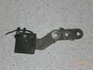
Radio Noise Suppression Capacitor NNW502820699 viewsThis is the radio noise suppression capacitor, part number LR020488 (previous NNW502820), that is mounted underneath and near the transmission. It is powered by fuse 10 amp F30E in the engine compartment. If F30E blows, (the fuse that also powers the transmission ECU), the problem is probably caused by the failed capacitor, not the ECU. A quick fix is just to disconnect the capacitor and replace the fuse as nothing bad seems to immediately result.
The above radio noise capacitor is not to be confused with LR004160, the ignition noise capacitor which is located under the black plastic engine cover on the right hand side above the air intake towards the rear of the engine.
The ignition capacitor is held on with a single 8mm bolt and a three wire electrical connector. Replacing the ignition capacitor as a routine maintenance prevention action at 100,000 miles, 160,000 km), has merit. It is a do it yourself kind of thing and easier to get at than the radio capacitor underneath.
|
|
Thread upload13 viewsImage uploaded in thread 74474
|
|
Thread upload14 viewsImage uploaded in thread 74474
|
|
Thread upload10 viewsImage uploaded in new thread
|
|

Regency Stages 2012128 viewsWorking hard, well almost! Radio duty for the Regency Rally at the Bath & West Showground (Shepton Mallet).
|
|
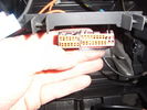
Hi Line stereo plugs with radio removed. Aux plug on the left14 views
|
|
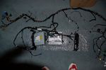
Sat-DVD-Radio Connected 194 views
|
|
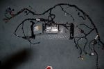
Sat-DVD-Radio Connected 280 views
|
|

Sirius Radio installed overhead58 views
|
|
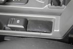
Little speaker to get nav instructions while listening to the radio131 viewsThe sound of the PDA is routed to the Aux input of the car. this way MP3 music and Nav instructions get to the car\'s audio system. But when you want to listen to the radio and also hear nav instructions, you can\'t hear them both through the car radio. For that I mounted a little speaker.
|
|
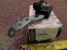
Radio Noise Filter Transmission Electronic Control Unit913 viewsThe jpg shows part number LR020488, a noise suppression capacitor located underneath on a bracket on the right side of the transmission forward of the selector shaft lever. The suppressor is connected to the transmission wiring harness and prevents solenoid operating noise affecting the audio system.
Failure of the capacitor is most often discovered as a result of either black smoke from below and or the blowing of 10 amp fuse F30E located in the engine compartment fuse box. This fuse protects the power circuit to the Transmission Engine Control Unit. When the fuse blows, the engine will still run however you have no gears, hence movement of the 3 is inhibited.
Anything over eight years in service is considered good capacitor life. If the capacitor does fail and fuse 30 blows, a quick fix is just to disconnect the capacitor and replace the fuse.
The capacitor might be missed by the DOT/FCC but the 3 does not seem to mind. With the filter disconnected, solenoid noise might be heard on some radio stations but at least the 3 would be in motion.
|
|

140 views
|
|
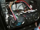
207 viewsHands Free Kit install A Class
|
|

45 viewsthe radio is going to be taken out and replaced with a double in dvd/gps/tv
and the sat nav cubb is going to have a custom made iphone holder inside of it (if all goes to plan anyway)
ill upload pictures when its done
|
|
|
|
|
|