| Search results - "plug" |
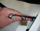
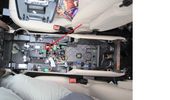
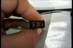
heated seat (base) wiring411 viewsThe Small connector takes the plug from the seat back pad, the larger connector (with red) is fitted into the multiplug casing uder the seat - the male side of this is already pre-wired.
|
|
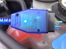
1 FBH Loom70 views
|
|
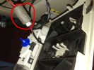
10 Telephone / Voice Mic Plugs70 views
|
|
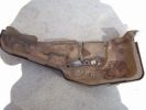
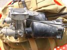
Compressor original cover656 viewsThe rock punctured straight through the plastic cover, snapped the soft compressor bracket and tore open one of the loom plugs.
|
|
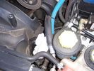
201 viewsRemoval of Intercooler hose, don't forget to plug the hole, don't want anything to fall in there
|
|
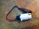
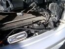
12S plug with Ctek lead attached29 views
|
|

12S plug from eBay and Ctek lead (provided with MXS-10) - before cutting the ring terminals off.28 views
|
|

Thread upload25 viewsImage uploaded in thread 176268
|
|

Thread upload15 viewsImage uploaded in thread 153386
|
|

Thread upload9 viewsImage uploaded in new thread
|
|

Thread upload9 viewsImage uploaded in thread 167536
|
|
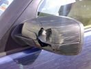
Damage from Mud plugging on way to Barston Ford183 views
|
|
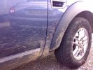
Mud plugging on the way to Barston Ford173 views
|
|
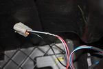
109 viewsThis is the plug for the accessory socket at the rear of the cubby box. On commercial D3 such as this one, there is no accessory socket so this plug is unused. I tapped into the 12V wire as an ignition feed. This will feed a relay coil which opens up power from the aux battery. Like this I can still retro fit and make use of the accessory socket later on.
|
|

most connector with 4 pin plug for usb/ipod module 57 views
|
|

27 viewspdc main plug?
|
|

door loom plugs for window & audio12 viewsthe two plugs for the window & audio contros
|
|

B post door plug14 viewsRear door wiring harness plug to B post
|
|

Rear door audio plug 15 viewsRear door audio plug
|
|

Terratrip 202 V4 possible discrete location140 viewsAttached to ashtray - allowing removal / unplugging when not in use by pulling out the ashtray.
Terratrip is an odometer for use in rallies / raids - very popular with the French when used in conjunction with a roadbook. A mechanical backup in case GPS signal is lost on modern odometers like the Globe 800 I propose to use.
We'll see if there are reflection issues from the screen.
|
|
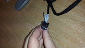
black plug for rear heated seat12 views
|
|
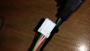
white plug for rear heated seat11 views
|
|
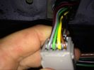
Reverse Camera plug9 views
|
|
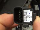
Reverse Camera plug9 views
|
|
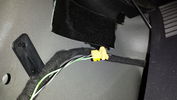
Plug behind rear quarter panel trim12 views
|
|
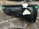
Rear door Window mechanism and motor No grey Plug AAH2227001AA6 views
|
|
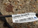
Upper Tailgate Loom (no Camera) BH22-14A583-AA7 viewsOne Pin loose on grey plug
|
|
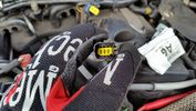
RH Glow plug connector16 views
|
|
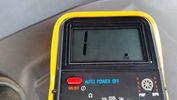
Resistance Ohms Failed glow plug13 views
|
|
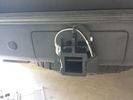
Rhino Hitch429 viewsCover fitted over the 75A Anderson plug with Rhino Hitch fitted which is a Class IV hitch. https://www.facebook.com/DifferentialPartsUS
Fits the Disco 3, Disco 4 and Range Rover Sport
|
|
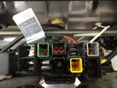
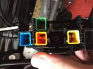
Seat plug 217 views
|
|
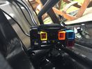
Seat Plug 318 views
|
|
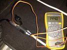
Seat Plug117 views
|
|
Marine Plug346 viewsRunning a cigarette plug rated at 15a with a plug rated at 20a drawing 5a at 12.8v will generate more heat than you want. Use Anderson or hardware.
|
|
Plug2 views
|
|

Front Differential Description and Operation1543 viewsThe 4 page pdf describes of the operation of the front differential plus displays an exploded view of the front differential.
The fill plug is item 36 and the drain plug, item 8.
It is suggested one first unscrew the fill plug before unscrewing the drain plug - and it might take two different wrench sizes, hence get this detail sorted out before any oil drains out.
|
|
24 Dash Loom42 views
|
|
28 Dash Loom49 views
|
|
Thread upload3 viewsImage uploaded in thread 198799
|
|

Headlight washer plugs83 views
|
|
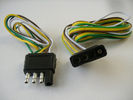
4 pin NAS flat connector from NAS small trailer382 viewsThe connector with the three exposed pins is the end that would commonly be located at the trailer hitch end, (front), of a small NAS lightweight trailer that has no electric brakes. This plug would connect into the flat 4 pin connector at the rear of the 3.
Note the order of the pin functions and wire colours: White is ground; the next pin is for tail/marker lights using the Brown wire; the Yellow conductor is for the left turn signal, and the far pin uses the Green conductor for the right turn signal.
There is no separate brake light conductor as NAS spec vehicles most often combine the brake and signal light functions to the same bulb filament rather separate filaments in different bulbs. The LR factory harness resolves that design difference.
Fortunately, the Land Rover NAS assembly pin order for the 4 pin flat plug maintains the above described conventions.
|
|
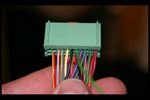
plug footwell i think115 views
|
|
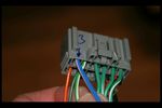
plug to footwell111 views
|
|

JST Plug60 views
|
|
Thread upload0 viewsImage uploaded in thread 154179
|
|

Thread upload35 viewsImage uploaded in thread 92518
|
|
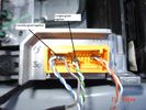
80 views
|
|

Add A Circuit Littelfuse Data sheet2278 viewsThe switch connects to what Littelfuse brand calls an Add-A-Circuit model FMH200BP which is an adapter that plugs in place of a Mini fuse and then has space for two Mini fuses, (original and a second one). In this install, only the original 5 amp fuse was used - adapter was so as to route power from fuse box thru fuse, then rocker switch, and then back to fuse box.
Before you install the Add A Circuit for this application, take an ohm meter and trace out the circuit path of the four slots that fuses could insert into. The path is more complicated than one might first think. As such, the orientation of the fuse holder in the socket matters for this application - that is for a circuit diverter, rather than accessory adder.
|
|

Alternator female plug looking down into top373 viewsThis shows the plug connected to the alternator wiring harness looking down into the top of the plug.
The cavity marked 1 is the AS or BATT SENSE and the wire colour most likely has Brown/Green on it.
The cavity marked 2 is the RC or ALT CON and the wire colour most likely has Red/White on it.
The cavity marked 3 is the L1 or ALT MON and the wire colour likely has Green/White on it.
I say "most likely" as the wire colours are not always the same on all vehicles.
Also the terminal 1 conductor destination is more likely C0570-175 rather than per the jpg.
The #3 pin is located closest to the big B+ terminal.
|
|
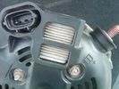
Alternator Plug and B+ terminal918 viewsPictured is the rear of the older Land Rover part # YLE500190 alternator showing the shiny cooling fin of the Regitar VRH2005-142 regulator under.
The first pin in the far left side of the connector is numbered #1 in the LR electrical wiring diagrams and is Battery Voltage Sensing (BVS); the middle pin, #2 receives a Pulse Width Modulated (PWM) signal from the Engine Control Module (ECM), and the right pin, #3 carries a PWM signal back to the ECM. Terminal Pin #2 on the LR wiring diagrams is called Alternator Control or ALT CON; Pin #3 per LR is called Alternator Monitoring or ALT MON.
Pin #1 is similar to what in older designs used to be called A or Batt, but is now called by Denso, S, AS, or Alternator Sensing for this design. Pin #1 also provides power to excite the alternator at startup until the PWM instructions over ride the battery voltage info. Land Rover calls the electronics under the pins a Smart Regulator, ironic, as it has to follow orders from the ECM rather than give the orders - new age thinking I guess. This is different from older design internal regulators that look at just the battery or the electrical buss voltage and then decides itself what to do.
It is almost like we are back to the external regulator designs of old, except that the ECM may decide that instead of telling the alternator to make more power, to load shed, and hence shut down the heated windscreen, seats, or whatever other electrical loads it decides are appropriate. My view is that the "smarts" are in the ECM and that the "regulator" should be regarded if not dumb, then as being a slave to the ECM.
|
|
Thread upload5 viewsImage uploaded in thread 142542
|
|
Thread upload20 viewsImage uploaded in thread 187006
|
|

Glow_Plug_-_Sectional20 views
|
|
260 views
|
|
Thread upload6 viewsImage uploaded in new thread
|
|
Thread upload6 viewsImage uploaded in new thread
|
|
Thread upload3 viewsImage uploaded in new thread
|
|

Thread upload4 viewsImage uploaded in thread 106051
|
|
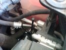
Vertical Breather Hose before cutting off OEM cap.1778 viewsThis shows the plastic vertical breather tubing and OEM cap prior to being cut off. The tubing is located on the driver side at the front near the radiator. One cuts about 3/4" to 1" off from the top. The TSB says 20mm.
I tried blowing thru the cut off piece and was not very successful. The cap seemed plugged. I am beginning to think that there was a very good reason for Land Rovers's Technical Service Bulletin, (TSB).
|
|
Thread upload13 viewsImage uploaded in thread 65718
|
|
Thread upload12 viewsImage uploaded in thread 65718
|
|
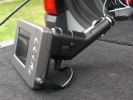
Monitor monted on 12v plug43 views
|
|
Thread upload6 viewsImage uploaded in new thread
|
|
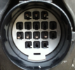
Connector without blanking plug282 views
|
|
LHS Headlight Plug Socket24 views
|
|

Searching The C2084-C004153 views
|
|
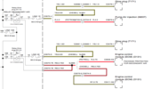
D3_Glow_Plug_Relays20 views
|
|
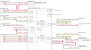
D3_Glow_Plug_Wiring_119 views
|
|
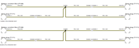
D3_Glow_Plug_Wiring_216 views
|
|
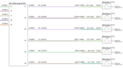
D4_Glow_Plug_Wiring16 views
|
|
Thread upload9 viewsImage uploaded in new thread
|
|
Thread upload6 viewsImage uploaded in new thread
|
|
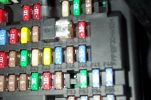
Tapa-Circuit Fuse Tap411 viewsTapa-circuit fuse tap fitted in existing fuseway provides extra fuseway which I have used to hard wire my Tomtom Sat Nav PDA. The fused output feeds into a female socket (Cigar lighter sized) into which the tomtom power adaptor is plugged. All hidden away behind the glove box.
|
|
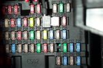
Tapa-circuit Fuse Tap435 viewsTapa-circuit fuse tap fitted in existing fuseway provides extra fuseway which I have used to hard wire my Tomtom Sat Nav PDA. The fused output feeds into a female socket (Cigar lighter sized) into which the tomtom power adaptor is plugged. All hidden away behind the glove box.
|
|
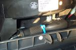
Hard wired tomtom497 viewsThe fused output from a tapa-circuit feeds into a female socket (Cigar lighter sized) into which the tomtom power adaptor is plugged. All hidden away behind the glove box.
|
|
Thread upload15 viewsImage uploaded in new thread
|
|
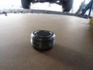
Front Diff Oil Plug 70k After75 views
|
|
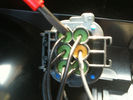
190 viewssignal wire pin 3 on rear of D4 rear light plug fit 6 ohm 50 watt resistor across here and common ground Pin 5 yellow terminal shown in next pic
|
|
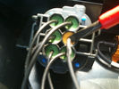
170 viewscommon groung wire pin 5 yellow on rear of d4 light plug
|
|
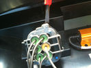
172 viewsorientation peg on rear of D4 light plug
|
|

Thread upload2 viewsImage uploaded in new thread
|
|
Thread upload14 viewsImage uploaded in thread 177861
|
|
Cyperdyne plug-in voltmeter111 views
|
|
ac plugs on RHS next to fridge190 views
|
|
Powered directly from plug151 views
|
|
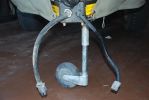
added battery connector for charging direct from vehicle - the solar panel also plugs in here, so can be used for vehicle or trailer charging108 views
|
|

Blanking Plug side shot398 views
|
|

Glass Roof Blanking plug363 views
|
|
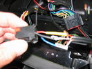
88 viewsdvd plug inthe back of the radio
|
|

19 views
|
|

Thread upload22 viewsImage uploaded in new thread
|
|
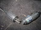
Vibration-proof Engel plug - simply unscrew normal 12V plug119 views
|
|

80 views
|
|
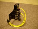
FASKIT on end view 864 viewsEnd and rear view of the FASKIT. Yellow lines are as shipped for hooking to the air supply; one line to valve/filler and other is to gauge. I will modify the arrangement to delete one of the yellow lines such that gauge line plugs into where the second yellow line is right now,(will be only one yellow tube), and then the air source line will plug into the port controlled by the valve, (hidden in this view but visible in other view). When white valve is in the ON position, gauge will read air source pressure, and be available to supply air to any of the selected four air springs. When valve is closed, the gauge will show individual air pressure in each of the air springs when a jumper is run between the gauge Schrader valve and the appropriate air spring Schrader valve.
|
|
154 views
|
|

fbh69 views
|
|
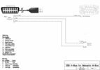
64 viewsOBD2 adapter to FBH wiring diagram, corrected and labelled for plug view.
|
|
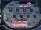
FBH Plug12 views
|
|
Thread upload16 viewsImage uploaded in thread 122403
|
|
Thread upload15 viewsImage uploaded in thread 122403
|
|
Thread upload8 viewsImage uploaded in thread 136766
|
|
Thread upload7 viewsImage uploaded in thread 136766
|
|

Thread upload1 viewsImage uploaded in thread 198799
|
|

Thread upload2 viewsImage uploaded in thread 198799
|
|

Thread upload1 viewsImage uploaded in thread 198799
|
|

Thread upload0 viewsImage uploaded in thread 198799
|
|
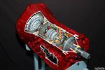
Ford 6R60 six speed cutaway showing torque converter.2198 viewsThis is a cutaway of the Ford 6R60 six speed which is a Ford license built version similar to our ZF 6HP26 six speed speced on early 3's.
The newer 3's and 4's have the ZF 6HP28. The Ford version is called the 6R80 and variations of it are used on the Raptor. As such, the Raptor metal pan can be installed on the 3's tranny but the deeper Ford Raptor pan does not have a drain plug.
|
|

smb plug225 views
|
|
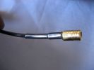
smb plug193 views
|
|
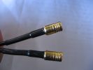
smb plug184 views
|
|
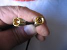
smb plug266 views
|
|
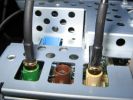
smb plug334 views
|
|

Thread upload7 viewsImage uploaded in new thread
|
|
37 viewsfront diff plug doing its job
|
|
51 views
|
|
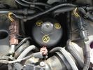
Glowplugs70 views
|
|
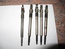
Glowplugs64 views
|
|
Glowplugs65 views
|
|
Glowplugs50 views
|
|
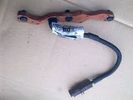
Glowplug Harness44 views
|
|

1 views
|
|

2 views
|
|

Thread upload2 viewsImage uploaded in new thread
|
|
Thread upload3 viewsImage uploaded in new thread
|
|

Thread upload3 viewsImage uploaded in new thread
|
|

Thread upload4 viewsImage uploaded in new thread
|
|

Thread upload4 viewsImage uploaded in thread 177978
|
|

Thread upload3 viewsImage uploaded in new thread
|
|

Thread upload2 viewsImage uploaded in new thread
|
|

Thread upload3 viewsImage uploaded in new thread
|
|

Thread upload3 viewsImage uploaded in new thread
|
|

Thread upload1 viewsImage uploaded in new thread
|
|

Thread upload2 viewsImage uploaded in new thread
|
|

Thread upload1 viewsImage uploaded in new thread
|
|

Thread upload3 viewsImage uploaded in new thread
|
|

Thread upload2 viewsImage uploaded in thread 177978
|
|

Thread upload5 viewsImage uploaded in new thread
|
|

Thread upload3 viewsImage uploaded in new thread
|
|

Thread upload2 viewsImage uploaded in new thread
|
|

Thread upload2 viewsImage uploaded in new thread
|
|

Thread upload4 viewsImage uploaded in new thread
|
|

Thread upload3 viewsImage uploaded in new thread
|
|

Thread upload1 viewsImage uploaded in new thread
|
|

Thread upload2 viewsImage uploaded in new thread
|
|

Thread upload1 viewsImage uploaded in new thread
|
|

Thread upload4 viewsImage uploaded in new thread
|
|

Thread upload1 viewsImage uploaded in new thread
|
|

Thread upload2 viewsImage uploaded in new thread
|
|

Thread upload3 viewsImage uploaded in new thread
|
|

Glow_Plug_err_glowing18 views
|
|
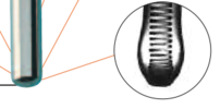
Glow_Plug_Tip_Swell16 views
|
|

Thread upload3 viewsImage uploaded in new thread
|
|
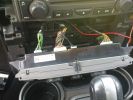
Heater control wiring138 views
|
|
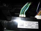
heated seats30 views
|
|
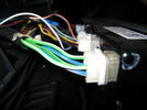
heated seats27 views
|
|
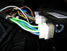
hvac controller124 views
|
|
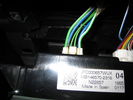
cable onto controller107 views
|
|

Ignition Coil-On-Plug Removal.pdf418 views
|
|

towing plug39 views
|
|
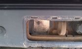
Outside connection to the compressor14 viewsFrom the compressor which is in the booth, the air hose runs to the back of the car.
I was able to install the connector in the space of the second trailer plug (which wasn't installed anyway).
|
|
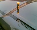
remove plug - cut to length346 views
|
|
remove the plug328 views
|
|

iPod connection12 viewsPictures of plug pins break in solder and finished installation Jack lead iPod connection
|
|

D4 Glowplug Afterglow 3.8 Amps24 views
|
|

D4 Glowplug Afterglow 0 Amps 17 views
|
|

Glowplug 2-wire test24 views
|
|

Glowplug 4-wire test19 views
|
|
power plug21 views
|
|
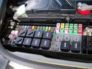
Picture of the engine compartment fuse panel5778 viewsEngine compartment fuse panel located near the battery. This is where F3E, (5 amp), F26E, (20 amp), Fuseable link 10E, (60 amp) and Relay 7E, the now upgraded 70 amp air compressor motor relay, part number YWB500220, (E is for Engine compartment fuse box), are all located. Fuse F35P, (5 amp), is inside the Passenger compartment behind the lower glove box door.
To keep the suspension from going down to the stops when driving, (or parked), it appears that it is only really necessary to remove F26E to depower the exhaust valve and generally keep all the valve block solenoid valves in a closed position trapping whatever air is within the air springs. F3E gets its power thru F26E, so when F26E is removed, the F3E circuit is automatically de-powered. F35P is more interesting in that battery power goes thru the ignition switch and F35P and then into the air suspension control unit. Apparently however, if F26E is removed, removing the F35P is not needed even when the engine is running.
With all fuses still in, if you have a problem, in practice, ideally, the compressor still works and will raise the 3 to an appropriate height. If so, one can then shut the engine off and allow the computers to go to sleep and then you remove the fuse(s). In actual practice, it seems that one need only pull the F26E fuse and can do so with the engine running. All the same, one might consider that the 3 is first a mobile computer, and secondly a 4x4. Computers prefer to go to sleep before the plug is pulled on them, however given that F26E circuit is always alive, then the computer never sleeps. With the fuse(s) pulled, and if you are still up, you can now be a 4x4 instead of a low rider. The whole purpose of the fuse pulling exercise is to depower the one and only system exhaust valve that is physically located within the compressor unit, (to keep it from opening), and secondarily to keep closed the four air spring solenoids within the block valves. This also shuts the air compressor down and stops the air compressor from making air even if the compressor is still good. That is why you initially need the fuse(s) in to allow the compressor to make air if it can.
|
|

Switch is blue colour thing thru the rectangular opening.3177 viewsThe blue coloured plastic bit thru the rectangular opening is the brake light switch. The fist time, I found it easier remove the switch by dropping the horizontal plastic panel, (two screws), and then slipping my hand in and rotating the switch clockwise 1/4 turn. The second time, I was able to remove the switch thru the rectangular opening and did not need to remove the horizontal lower panel. Obviously, I had to remove the sloping knee pad panel, (note sort of hinged at the bottom so pull back from the top.)
Regardless, do not touch the brake pedal - just let it sit where it wants to. One has to first remove the angled knee pad panel that sits under the steering wheel. It can be pulled from the top corner at the door side. Pulling releases a pair of those U shaped metal clips that LR loves so dearly. You have to pull quite hard. The bottom is held by a couple of plastic fingers in a couple of slots so you pull at the top till the two clips release and then rotate the panel and pull upwards a bit.
To remove the switch, you rotate it clockwise and pull outwards. Rotating the switch clockwise automatically retracts the plunger back into the switch body away from the brake pedal arm.
Similarly when you install the new switch, the required 1/4 turn anti clockwise rotation action releases the plunger so it lays up against the brake pedal arm and at the same time, secures the switch in place.
To remove the electrical wires, the switch will drop below the horizontal pad and hang from the wires so unclipping the electrical connector plug is fairly easy to do.
|
|
110 viewsview of wires inside dash (from where plug was removed). I ran them through the pre-existing slit in the top of the glove box to wiring loom connector.
|
|

98 viewsPlug removed from left hand side of dash to locate wires from clove box
|
|
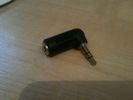
101 viewsstandard 3.5mm headphone plug/socket extension
|
|
780 viewsDetailed view of hitch and Anderson plug
|
|

Placement of mains plug39 views
|
|

Mains plug glued in place29 views
|
|

Placement of mains plug26 views
|
|

EPB Actuator plug28 views
|
|

AUX Panel plug59 views
|
|

AUX panel plug58 views
|
|

10 viewsPlug on electric memory seat
|
|

67 viewsfill and drain plugs (rear diff)
|
|
50 viewsspecial tool for sump plug
|
|
45 viewscleaned sump plug
|
|
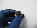
51 viewsdirty sump magnetic plug
|
|
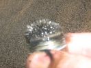
Rear diff Plug79 views
|
|

battery box multiplug7 views
|
|

Weep around the Mechatronic Plug....12 views
|
|
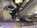
Checking the final level at the drain plug13 views
|
|
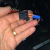
MOST Connector15 viewsThis connector plugs into the back of the Screen (TSD)
|
|

58 views
|
|
29 views
|
|

Replacement switch from RRS installed on LR3864 viewsThe switch shown is LR part number YUZ500020, the upper rear hatch release switch that is found on the Range Rover Sport.
The switch body is the same switch as on the LR3 except that there is no wiring disconnect on the LR3. Hence when the switch corrodes and requires replacement, the LR solution is to purchase a new handle and license plate light assembly. I instead cut off the old switch and installed a JAE mating connector to the existing wiring and hence just plugged the RRS switch in.
The replacement RRS switch snaps into the same rectangular space in the same manner as the removed LR3 switch, the difference is the JAE male wiring connector.
|
|
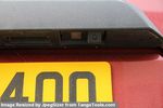
Number plate Camera 68 viewsThe camera includes a number plate light lens - left hand side of the camera.
Just plug in existing number plate bulb
|
|
Thread upload14 viewsImage uploaded in thread 115058
|
|

Headlamp Plug12 views
|
|
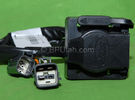
Harness section that runs behind the rear bumper.410 viewsThis is the harness section that clips up inside the rear bumper and includes the circular 7 pin, (6 flat +1 round), NAS socket, and also the 4 pin NAS flat connector.
The two small plug ends connect under the rear left tail light to the harness section that exits from the interior.
The Land Rover part number for the NAS trailer tow kit, (both cables), is YWJ500220.
|
|

Harness that connects inside left rear compartment.445 viewsThis is the harness section that connects behind the left rear interior access panel and exits thru the large grommeted hole to below/behind the left rear tail light.
Note the two rubber grommets on the harness as there is both an interior metal skin and an exterior metal skin behind the left tail light assembly.
The two light grey connectors plug into two existing connectors near the top of the rear left interior access panel. The two darker connectors plug into the second piece of harness.
There is no little separate fuse box either with the NAS spec harness. The fuse box is included with the UK 13 pin dual plug units. If there was a fuse box, it would be on this portion of the harness.
|
|
278 views
|
|

Thread upload25 viewsImage uploaded in new thread
|
|
mat plug close103 views
|
|

LR Electric Trailer Brake C2590 Female Connector606 viewsThis female connector, C2590, located up above and near the brake pedal is for the Trailer Electric Brake Controller hookup.
The Black wire in the bottom right is pin #3, the ground. The Blue wire to the left is pin #6, the Trailer Brake Controller output going to the rear trailer socket.
The White #4 wire is the 30 amp fusible link, (Link 6E in the engine compartment junction box), for the Brake Controller 12VDC power feed from the battery. Note that this would make a pretty good power source for CB radios and the like if no electric trailer brakes were required.
Pin #5 is a Green wire from the stop lamp switch, (the control input for the Brake Controller).
This plug is standard on all NAS (LR3) vehicles, but unlikely to be found on the D3 spec units.
|
|

Battery Maintainer pigtail sticking out of Grill726 viewsThis is all you see when everything is put back together - just the pigtail and Weather Pack blanking plug. Most often, I have it all tucked back behind the grill.
In winter, there may be a second cord hanging out as well - the 120 VAC power cord for the engine block heater, a tea kettle like element inserted in the engine block. NAS petrol V8's do not have the Fuel Burning Heater, (FBH), installed, but instead in cold area markets have the block heater element assembly available as a dealer installed option. There is an argument to say that the heating element is factory installed in all cold climate V8 gasoline engines, however the appropriate power cord is not. If true, this means that all one needs to purchase is the area specific power cord and plugging in / attachment to the engine block located block heater.
As such, you will often see a conventional 120VAC three prong power plug hanging loose out of the grill of most vehicles here in the wintertime. In summer, most drivers tuck the plug back behind the grill as it is no beauty mark.
|
|
Battery Maintainer switching box plug and CTEK Multi US 3300 charger. 706 viewsThe CTEK Multi US 3300 maintainer is just sitting there for the picture. In addition to topping up both batteries, the CTEK can provide power such that if the batteries were completely dead, there would be power to the door locks and hence, one could most likely still gain access via the remote once the starting battery charged up a bit.
The Land Rover recommended method is via the hidden key hole which is mechanical, however that presumes the mechanism is not frozen from lack of use. As such, the manual lock should be exercised at least once a year to ensure that it still functions.
The blanking plug sitting on top of the plastic box is of the GM Weather Pack series. That is what I like to use for vehicle wiring that is subject to moisture, (or not).
|
|
Compressor Air Drier 2044 viewsA view of the air drier - the black round thing to the right of the actual compressor cylinder head.
The general feeling is that the air dryer is responsible for most of the compressor problems now and that replacement of either the assembly or just the beads inside will probably revive one's compressor. In reality, the beads may have for the most part broken down and turned to dust plugging the internal filters. Hence replacement of the complete dryer unit has some merit.
The part number for the dryer assemble complete with the desiccant is VUB504700.
|
|
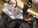
Compressor Electrical Plugs 1406 viewsThis shows the two electrical connectors; the two pronger is the power to the compressor, and the multi-pin connector carries control signals. Also the temporary red plug is where the 6 mm tubing from the centre valve block connects. This line carries both the compressor and exhaust air to and from the springs.
|
|
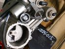
Compressor Exhaust and Inlet 1534 viewsThe two temporary black plugs cover off the 8mm and 10mm push fit lines to the air inlet and exhaust lines. Also visible is the worn threaded stud that I think was the initial failure mode.
|
|

NAS 7 Blade Round plus NAS 4 Pin Flat Vehicle end Socket527 viewsThis shows the function of each blade when looking into the connector at the vehicle end for the 7 pin NAS plug. The layout is the pin order for most new North American pickup trucks and the LR3/4.
The colour and gauge of the wires feeding into the back of the plug varies even within manufacturer model lines.
Also detailed is the flat 4 pin layout common on smaller trailers not having electric brakes. This includes most U-Haul rental trailers.
|
|
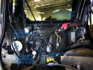
a few items being built in behind cover panel.442 viewsred inverter will have fluch mount plugs, air outloet will be flush, guage with window in lower pop-panel and switches and fuses for all rear items behind popout panel.
12v sockets being added as well, high and low.
|
|

LR3 AJV8 block heater location639 viewsThis 1 page pdf shows the screw in block heater location as related to the lower left side of the engine block.
|
|

LR3 Brake Wear Sensor Wiring1517 viewsThis 1 page wiring diagram pdf shows that both the front and rear brake pad wear sensors are part of a closed series circuit to ground.
In operation, when all is good, the series circuit is grounded and the amber brake wear warning indicator on the instrument panel is not illuminated.
When the pads on one wheel, either the left front, or right rear, become too worn, the respective sensor is "cut" which results in an open circuit condition. This causes the dash brake wear indicator to illuminate.
The circuit is like the old style Christmas light strings where one burned out bulb caused the whole string to go out.
A quick field fix to get the dash light to extinguish in lieu of replacing the sensor and pads etc is to disconnect the brake pad wear sensor and short across the two open conductors of the vehicle side connector plug. This of course means you now have a normal vehicle, one of the thousands that do not feature brake pad wear information systems.
|
|

ZF 6HP26 transmission fluid drain and refill procedure4040 viewsThis is the Land Rover instruction pdf and I note they have it right - that is remove the filler plug first, then the drain plug. Also before you attempt that, not only do you need oil, but also new fill and drain plugs as the sealing washers are deemed single use only.
|
|

ZF 6HP26 Land Rover Transmission specs1677 viewsThis is just two sheets of paper with various numbers related to the 6HP26 such as oil capacity, gear ratios, and torque wrench settings for the fill and drain plugs.
You may note that LR calls this ZF transmission the 6HP26 whereas ZF calls out the LR3 transmission as the 6HP26X. Just what the differences are, I am not certain however the X refers to 4WD or AWD use as opposed to solely 2WD.
Zahnradfabrik is what ZF is short for and translated from German, roughly means Gear Factory.
|
|

Rosen A10 Land Rover Installation Manual841 viewsThis is a 11 page pdf which is the Land Rover version of the A10 installation manual for our 3. It consists of a hundred plus sketches showing how and where to connect various cables, conductors and plugs.
|
|

Thread upload12 viewsImage uploaded in new thread
|
|
25 views
|
|

Battery compartment plug153 views
|
|
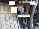
footwell location of plugs150 views
|
|
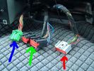
144 views
|
|

Thread upload8 viewsImage uploaded in new thread
|
|

Oil drain plug16 views
|
|

TDV6 oil filter and sump plug252 viewsUsed oil filter and sump plug from 2006 TDV6.
|
|
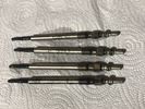
Thread upload4 viewsImage uploaded in thread 177978
|
|
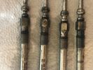
Thread upload4 viewsImage uploaded in thread 177978
|
|
Thread upload15 viewsImage uploaded in thread 177978
|
|
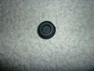
Firewall Plug539 viewsThis is the plug removed from the firewall, before cutting a hole to feed a wire through. Displace as much rubber as wire, so it is snug, but not to big, or you won't be able to snap it in.
|
|
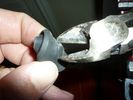
firewall plug run722 viewsThe rubber grommet from firewall plug, removed, with a hole cut in the middle. Instructions say to cut it to the center, but you can cut a hole out by bending it, and using a pair of diagonal pliers, removing excess material so you can fit the plug back in.
|
|
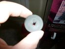
firewall plug run663 viewsThe rubber grommet from firewall plug, removed, with a hole cut in the middle. Instructions say to cut it to the center, but you can cut a hole out by bending it, and using a pair of diagonal pliers, removing excess material so you can fit the plug back in.
|
|
firewall plug run933 viewsThis is the engine side view, of where to poke the hole with a screwdriver to make a hole into the vehicle. You can barely see the edge of the hole. Note: The Rubber plug should be removed for this operation.
|
|
firewall plug run883 viewsScrewdriver poked through the firewall hole
|
|
firewall plug run919 viewsHow to get the cable from the engine bay to the rear of the vehicle.
|
|
firewall plug run855 viewsThrough the firewall to the right of the brake master cylinder. On left hand drive, this hole would be closest to the outside edge of vehicle.
|
|
Firewall Plug614 viewsFeeding a guide wire through the new hole.
|
|
close up of 1 1/4" access hole493 viewsView of the 1.25" inch access hole. You can reach your finger or a screwdriver in this hole to move the lever up or down. It will be fitted with a rubber plug when not in use (and when found).
|
|
cross view showing access hole503 viewsCross view of the 1.25" inch access hole. You can reach your finger or a screwdriver in this hole to move the lever up or down. It will be fitted with a rubber plug when not in use (and when found)
|
|
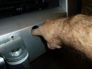
1 1/4" access hole for lever459 viewsAction view of the 1.25" inch access hole. You can reach your finger or a screwdriver in this hole to move the lever up or down. It will be fitted with a rubber plug when not in use (and when found)
|
|
Take the plugs out24 views
|
|
76 views
|
|
278 viewsA mess of cables. You can see the HD Radio antenna adapter coming out into the slot for the IHU. You can also see, if you look very closely, the original diversity antenna connector plugged into another adapter to go down to the HD radio unit.
|
|
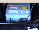
Back of DVD player as original connectors - unplug middle blue one out put to lcd399 views
|
|
panel removed plugs visible352 views
|
|
Removed side panel - 4 plastic plugs pulls off easy328 views
|
|
camera installed in towbar cover.363 viewsthere is a plug on the power and video connector so can easily be removed for towing
|
|

pink plug10 viewsnon lr plug
|
|

gas issue9 viewsnon lr plugs
|
|

contamination8 viewsnon lr plugs
|
|
Thread upload2 viewsImage uploaded in thread 189910
|
|
434 views
|
|
242 views
|
|

126 views
|
|

16 views
|
|

Thread upload15 viewsImage uploaded in new thread
|
|
Thread upload3 viewsImage uploaded in thread 174703
|
|

Thread upload4 viewsImage uploaded in thread 188108
|
|
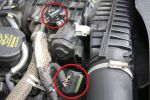
EGR Butterfly Valve Actuator and Air Box Connectors931 viewsRemove the 2 circled plugs.
|
|

18 views
|
|
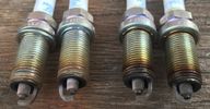
spark plugs, right ones are abnormal ?11 viewsthat is not LR engine, that Jeep's Hemi.
|
|
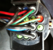
LHS Headlight Plug Back19 views
|
|
Thread upload2 viewsImage uploaded in new thread
|
|
31 views
|
|
28 viewsrear diff plug
|
|

Thread upload3 viewsImage uploaded in thread 163024
|
|

Transpo Regulator IN6349 Pin Assignment715 viewsThis pdf shows the Land Rover and Ford pin naming for the 3 pins in the receptacle of the Transpo IN6349 regulator that accepts PWM signals. This jpg is as if you are looking into the receptacle located on the alternator.
Also provided are the Transpo pin names that are in common use and that some may be more familiar with plus some comments re testing.
The IN6349 regulator is used in the newer LR part # YLE500390 alternator. For the older YLE500190 alternator, the regulator is a Regitar VRH2005-142 unit that is shaped a bit different than the newer IN6349 regulator. Externally, the main difference is that no shiny fins are visible on the rear of the newer YLE500390 alternator. The pin naming and numbering is the same for both and both alternators are interchangeable.
|
|
17 views
|
|
Thread upload16 viewsImage uploaded in new thread
|
|
Hi Line stereo with plugs still in place14 views
|
|
Rear of Hi Line stereo with plugs removed17 views
|
|
Hi Line stereo plugs with radio removed. Aux plug on the left14 views
|
|
Plugs removed from Hi Line Stereo 'as they hang out' of the dash15 views
|
|
Plugs from rear of Hi Line stereo 'as they hang out' of the dash15 views
|
|
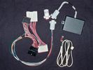
Electronic height controller trial kit251 viewsElectronic height controller kit incl trial extension looms & dummy plug
|
|
Thread upload1 viewsImage uploaded in new thread
|
|
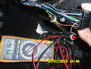
multiplugg under driver seat60 viewsThis picture is takin when diagnosing the heated seat element.
This show that there is 14volts to the elements on these wires.
|
|
305 views
|
|
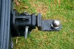
Shortened 299 viewsAfter removing 35mm from the tongue plug
|
|
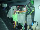
Thread upload17 viewsImage uploaded in new thread
|
|

Spark Plugs Removal318 views
|
|

Thread upload8 viewsImage uploaded in thread 160431
|
|
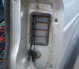
77 views
|
|

87 views
|
|
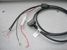
72 viewsplugs are cut off
|
|
Sump plug - Rear diff80 viewsSump plug - Rear diff. Check all the iron filings
|
|
Thread upload6 viewsImage uploaded in thread 168126
|
|

Thread upload16 viewsImage uploaded in thread 209090
|
|

Tekonsha Ford Brake Controller Adapter part number 3035-P274 viewsThis is the adapter cable between the Brake Controller and the existing C2590 female plug located near the brake pedal on NAS spec LR3's. The flat 4 pin plug of the adapter cable connects to the Controller; the rectangular 6 hole male plug to C2590.
There are only four conductors in the adapter cable, but one will see five pins within the Land Rover C2590 plug. The #2 pin is not required for the NAS setup. #2 pin is the circuit between the head lamp switch and vehicle side running lamps required in the civilized world.
The single pin at the bottom in the picture is #3 and on the Land Rover, a Black wire tied to ground. The other pin at the bottom and across to the left is #6, and Blue on the Land Rover. This is the Brake Controller output to the trailer socket at the rear.
#4 is the pin at the top left, and is a White coloured wire from the battery. Pin #5 is from the stop light switch, and is Green on the Land Rover.
Note that the adapter cable colours do not necessarily follow all the above referenced Land Rover colours.
|
|

Tekonsha P3 Brake Controller 90195 to Ford 3035-P wiring adapter plug311 viewsThis two page pdf is the general instruction for hooking up the Tekonsha part number 3035-P adapter cable between a Tekonsha P3 controller and the existing Land Rover/Ford plug, (called C2590 in the Land Rover wiring diagrams), that is hidden above the brake pedal.
The "Ford" plug, (C2590), is grey and is stuffed up above the brake pedal arm.
Mount the P3 controller appropriately and then connect one end of the custom cable to the P3 and the other to the "hidden" plug.
You will now have power for your trailer electric brakes in the round socket at the rear of your LR3; also no computer update from the Land Rover T4 unit is required. For once, it is plug and play.
If however, your trailer has LED tail lights, you may have trouble with the flashing of the trailer signal lights or non recognition by the 3 that a trailer is connected. As such, the little green trailer signal will not illuminate when a trailer is connected and the signal lights are used. This can affect the shifting of the transmission and much to your annoyance, the backup sensors will still be functioning rather than being auto disabled.
|
|

Tekonsha P3 Electric Trailer Brake Controller model 90195289 viewsOne model of electric brake controller that is commonly used on the LR3 is the Tekonsha P3 unit, model number 90195. It mates up to the LR3 with a custom "Ford" adapter cable, Tekonsha part number 3035P. No wire cutting or splicing is necessary - just mount unit and plug adapter cable in.
|
|
258 views
|
|

Thread upload1 viewsImage uploaded in thread 198799
|
|

Thread upload1 viewsImage uploaded in thread 198799
|
|

Thread upload0 viewsImage uploaded in thread 198799
|
|
Torque tune180 viewsPlug position.
|
|
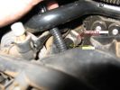
Torque tune184 viewsPosition of engine plug.
|
|
48 views
|
|
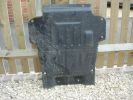
Lower engine bay tray316 viewsLower engine bay tray, 2006 Disco3 TDV6. Needs removing to gain access to sump drain plug.
|
|
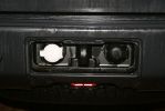
Twin Plugs49 views
|
|

Thread upload10 viewsImage uploaded in new thread
|
|
Voss System 203 connector 6 mm for valve blocks 905 viewsThis is Land Rover part number RQC000030, the Voss fitting for the axle valve blocks. I think it is a Voss System 203 6mm fitting, Voss part number 5 2 03 11 01 00.
The parts bag comes with the white plug inserted in the brass threaded bit with what is called the brass cutting ring placed on the tip of the white plastic plug. The idea is that one screws, (M10 x 1 thread), the brass insert into the appropriate hole with the white plug still in the brass insert. Once the brass is tight, (12 mm wrench), then the white plug is pulled from the assembly leaving the cutting ring down inside and under. One then pushes in the 6 mm tube end about 20 mm or so and the tube slides down thru the brass cutting ring, (2 internal sloped one way cutting ridges). When the tube is in far enough, one pulls upwards a bit and the ring cuts into the plastic such that the tube will not pull out. To remove tube, one unscrews the brass nut and all comes out, sort of like I have shown with the short piece of 6mm tubing. The white plug is a throwaway item upon install of the tubing.
|
|

electric plugs RRS inside wing behind rear brake light5 views
|
|

D3 plugs in inside wing begind rear brake light7 views
|
|

ZF6HP26X fluid fill checking procedure2256 viewsThis are the single page ZF instructions for checking the fluid level in the 6HP26X six speed automatic that is in the LR3.
Included sketches show where the fill and drain plugs are located and that it requires a 8mm hex wrench for the filler plug and a 10mm for the drain for the plastic pan.
|
|
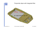
ZF_6HP26_Plastic_Filter_Pan_ combo.png1103 viewsThis is the plastic oil pan on the bottom of our ZF 6HP26X transmissions. Note the two round magnets at the right end of the pan; the drain plug is between them. The filter is the grey part and the vertical oil suction pipe is to draw oil up to the transmission from the filter element. There are 21 Torx screws around the perimeter and the pan gasket is O ring like in design where a half round channel is moulded into the plastic of the pan. The metal pan uses a more conventional flat gasket and in both cases, the metal mating surface of the transmission case is a flat machined metal surface.
|
|

Td5 play toy80 viewsmy 90 - Modified - Fullsize intercooler - with plug in Dastek chip
|
|
|
|
|