| Search results - "not" |
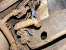
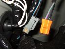
652 viewsNote blue rubber collar to hold lower part of control rod in arm.
|
|

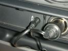
Put a link wire in these 2 holes (use a fairly thick wire ) - compressor will start ..you do not need the ignition on 941 views
|
|
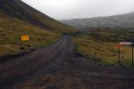
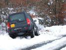
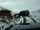
"Impassable" not for Discovery114 views
|
|
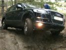
205 viewsQ7 working hard. note how little the suspensipon works. But - never got stuck!
|
|
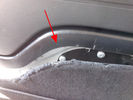
Rimozione pannello dalla sponda - Tailgate panel removing45 viewsPer togliere il pannello moquettato dalla sponda ho fatto leva con un cacciavite abbastanza grosso nel punto indicato, è stato veloce e non ho rovinato niente.
To remove the carpeted panel away from the tailgate I used a big enought screwdriver at the point indicated, it was fast and I have not ruined anything.
|
|
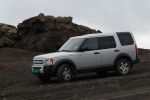
At Reykjanesfólkvangur not far from Reykjavik134 views
|
|
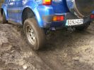
188 viewsJimny. Note how well the suspension works.
|
|
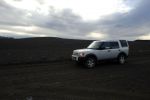
Not much of green118 views
|
|
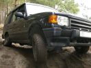
199 viewsSuspension working nicely. Thia model has no difflocks - not to mention electronics - to control wheel spin, so it needed speed to get through some points.
|
|
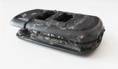
Tagliare lungo il perimetro della chiave - Cut along the key perimeter17 viewsI gusci sono saldati ad ultrasuoni. Con il disco tagliare lungo il perimetro della chiave in corrispondenza della giunta: lo spessore è di circa mm.3. Io non sono andato fino in fondo per evitare di danneggiare qualcosa, una volta inciso il solco per mm.2,7 ho fatto leva col cacciavite e ho strappato il materiale restante.
The body is ultrasonically welded. With the disc cut along the perimeter of the key in correspondence of the joint: the thickness is approximately 3mm. I have not gone all the way down
|
|

Shame it\'s not video coz you would hear my tap dancing so much better194 views
|
|

Snow34 viewsBut not much of it
|
|
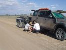
03 The first bit of tyre/wheel problem251 viewsSomewhere in the Australian outback on a 45 deg C day in Jan 08, a D3 had a bit of a flat tyre problem. "No worries, mate" st we had 3 spares (plus 2 more if we abandon the trailer), 150l of water, 4 days of food, and an EPIRB if things really go crook. The first clue that this was not a "normal" flat was when I handled a wheel nut and ended up with a blister from a burning hot nut (the ambient wasn\'t THAT hot).
|
|
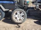
04 Damaged Tyre301 viewsYes, there\'s no doubt that this was a flat tyre. The ultra hot wheel nuts, look of the flat (note in a later photo that the back of the tyre appeared okay) and increased fuel consumption should have been a clue, but it was 45 deg C, and we had been doing about 105 km/hr on a dirt road for hours, so we just assumed it was a flat = WRONGO!
|
|
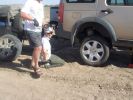
06 Spare tyre on and still suffering from hot wheel nuts296 viewsManaged to get ultra hot wheel nuts back on the spare (using the original 19" D3 wheel, vs the 19" RRS wider wheel which blew - shown in left of photo). Pity we didn\'t note that the disk brake was EXTREMELY hot at this time.
|
|

07 Back side of failed tyre340 viewsThis is the back of the blown tyre. It looks like any other worn tyre which has run a bit while flat. Note that we were running on wider 19" RRS wheels (have 4 19" MTRs + 1 old A/T on the original 5 wheels). Also have a rear-mount spare tyre holder which is really convenient with the wider rim and the fact that the tyre was still hot (it had some melted rubber on the other side!!)
|
|
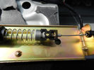
Cavo nel morsetto - Cable in clamp48 viewsHo inserito il terminale rotto nel morsetto: bisogna sforzarlo molto e ho praticato una cava attraverso il foro della vite con una punta in modo che il terminale non possa scivolare.
I entered the terminal broke into the clamp: you have to force it a lot, and I practiced a quarry through the screw hole with a bit so that the terminal can not slip.
|
|
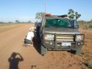
08 D3 stranded with a seized smoking wheel315 viewsAbout 1 hr after replacing the blown tyre, strange noises emanated from the stability control system and speed dropped off. Then I looked in the rear view mirror, and noted a cloud of dust along with a whiff of black smoke. This led to a very quick stop (no traffic on this route for over a week, so no worries about having to signal exiting the road). Took a look and WOW. The right rear wheel was glowing a dull red colour, and burning rubber smoke was wafting from the red glow over the fuel lines.
|
|
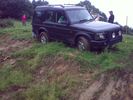
Almost a roll, but not quite...56 viewsI\'d \'launched\' myself at a 6ft hill and got to the top- but at an angle- the offside rear gripped and pulled us around to the right- perilously close to the edge... time for spare undies I think...
|
|
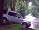
DickieDisco trying not to get wet!57 views
|
|
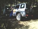
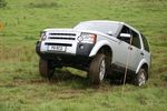
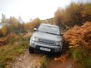
Freelander trying hard.107 viewsStill not stuck but getting there. In the end pulled it out with a Defender. Picture taken at Offroad-Training in Linthe/Germany
|
|
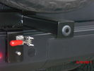
Sensor bar33 viewsSensor has been moved out to tire carrier where it should be. It does not pick up the tire anymore. "no faults".
|
|
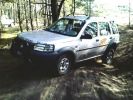
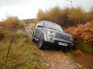
Still trying to prove it can hold up104 viewsFreelander not stuck - yet :)Picture taken at Offroad-Training in Linthe/Germany
|
|
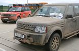
Silverstone Media Day87 viewsTook 3 cars for display .... a RRR members genuine 2005 RRS G4 & another members off-road modified RR p38a
|
|
Not stuck - only got out to take a picture :) Picture taken at Offroad-Training in Linthe/Germany142 views
|
|

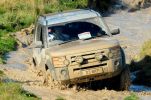
The s2a could not make this one - too deep.447 viewsGot towed through with a dead engine by a Tdi Defender - Betsy is petrol and needed a gallon of WD40 to get going after this!
|
|

10 Cracked smoking parking brake drum338 viewsNote the crack in the face of the brake. This showed mangled parking brake springs and other bits. Also a bit of melted rubber was drooling out of the crack. Started to remove the brake caliper and enjoying the flies in 45 deg C heat. Ah, the wonderful Aussie climate in January.
|
|
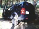
Compressor cover damage757 viewsAnother shot of the hole in the plastic cover
|
|
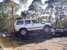
Tyre hill 2260 viewsNot so lucky - Jeep got stuck on top of the mound
|
|
Windich Springs, People not in our group221 views
|
|
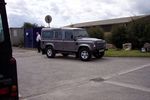
New Defender35 viewsTrade in of old Defender 90 and New Defender 110
Stratstone Pickering - Very friendly, good deal, but....
Same old Stratstone - not complete when collected.
|
|
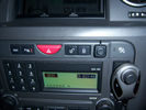
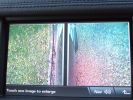
Input change button, rev camera cannot be overriden67 views
|
|
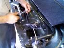
Putting all the bits back in52 viewsNotice the rope (Kevlar) coming out of the actuator box on the right side.
|
|
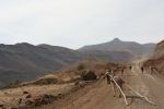
Will this stay the same for another 2000 years?126 views
|
|
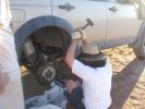
11 Lesson in removing a jammed brake assembly in the Outback379 viewsSpent the next 4 hours doing this to my D3. Gave the photos to Land Rover dealer and they did not think this constituted abuse of the vehicle. I thought that was charitable, but if we hadn\'t done this, the tow back to civilisation would have been even longer.
|
|
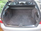
Mercedes E320 Boot19 viewsPlease note, any marks are just the pile of the carpet.
|
|

12 Half way through removing a jammed disk brake in the Outback297 viewsThis was just before breaking the sledge hammer. Note we luckily carried a spare hammer. Ended up using (or breaking) every tool we had on this little repair job. Bed sheets are a good way of gathering the bits to show for the inevitable warranty claim.
|
|

15 First sign of bits of parking brake failure336 viewsNote the complete lack of pad from the parking brake. Not only was there no composite brake material left, but the drum was somewhat twisted and connecting bits all smashed. Also a small drip of melted rubber from wheel bearing parts....
|
|
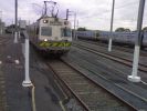
Do Not Park Trucks On Railway Lines!182 views
|
|
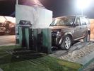
The obstacle...14 viewsThis what we had to push. You cannot believe how heavy this is. It looked easy, but let me tell you, I have seen many groups of 3 young tough guys curse and sweat...
|
|

Ready to winch a friends disco 4 194 viewsback of the picture you can just see another freinds (luvbus) disco 3 acting as balast to stop the disco 4 pulling me down hill
|
|
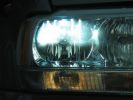
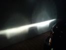
H7R Headlight retrofit H7R HIDS4U notice no light in bottome half of the bowl98 viewsThis is how a retofit HID should look in a reflector headlight
|
|
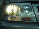
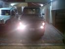
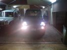
halogen bulb - some overspill but as its one third as bright this is not seen as glare. but add 100w bulbs and you will get glare95 views
|
|

My 2 Dogs and the b**ch128 viewsOur 2 dogs and SWMBO is not really a bitch.
|
|
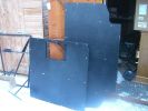
load bed with hatch (hatch lid not in phone)138 views
|
|
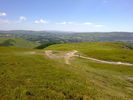
Look what we got up! Not bad in standard spec and 16", mixed, road tyres, I guess!43 views
|
|
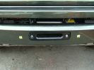
Hawse almost flush, not the neatest cutout but it won't be on view much941 views
|
|
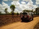
D3 in Litchfield National Park, on another part of the Reynolds Track51 viewsAnother shot of the flood plains and the magnetic trmite mounds.
|
|
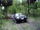
D3 in the Mary River Flood plains50 viewsFamily was down South with the In-laws, so I went for a drive on Boxing Day - which is the monsoon time, or \'The Wet\'. Was doing a test run with the off-raod trailer in preparation for the trip I was planning to the Kimberley six months later. Couldn\'t quite make it out of the creek, so a self-recovery was in order. Good thing it all worked, as I didn\'t see another car in over four hours. They were too smart to drive down the track I was on!
|
|

2010 D4 Official Release Notes159 views
|
|
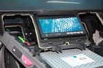
108 viewsTest fitting the screen. The bottom edge of the rear cover of the screen has been already dremeled off in this pic, notable as the circuit board can be seen.
|
|
91 views12V socket done. This is permanently powered by the Aux battery. Another one was done on the other side, though that one required drilling the hole with a 29mm hole saw as there wasn't an unused hole on that side.
|
|
81 viewsCarPC closed and ready for mounting. Note the modification to the rear of the case to allow extra USB sockets attached to the motherboard pins.
|
|
Not in place21 views
|
|
Battery226 viewsInterstate vs Deka = DEKA Do not buy interstate batteries.
|
|
203 views
|
|

these brands not permitted to park24 views
|
|
Roof Control panel25 viewsWell.. In reality it does not look as bad.. ;)
|
|

96 views
|
|

97 views72 hrs poste bite, not neck swelling
|
|
3mm brake pads...not27 views
|
|

Opaque switch cover119 viewsKR switch on:off:on used for front and rear spots - but LEDs not visible with coloured switch cover!
(Located in sunroof switch position)
|
|

Terratrip 202 V4 possible discrete location140 viewsAttached to ashtray - allowing removal / unplugging when not in use by pulling out the ashtray.
Terratrip is an odometer for use in rallies / raids - very popular with the French when used in conjunction with a roadbook. A mechanical backup in case GPS signal is lost on modern odometers like the Globe 800 I propose to use.
We'll see if there are reflection issues from the screen.
|
|
black house (temple)16 viewsanother art folly
|
|
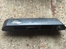
Rear Door handle in Metalic black from 2013-2013 D4 Camera model not same as my 20119 views
|
|
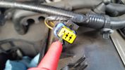
Test probe measure voltage18 viewsDo NOT insert the test probe into the connector as this can damage the terminal.
|
|
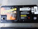
Deka 9A49 AGM Intimidator327 viewsThe Deka 9A49 AGM Intimidator makes an excellent primary battery alternative to the factory or Interstate. Made in US of premium quality. This is an excellent match with the Traxide system w/another Deka or Yellow Top optima.
This will behave properly in your D3/4 LR3 with slightly less wear and tear on your alternator.
|
|
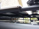
solar panel install356 viewsAt least at this point, I mounted it by using Clear Silicone RTV. This stuff is kind of like glue, but can be removed. If it doesn't hold up after curing and driving, I'll remove it and come up with another plan. I used heavy cable ties on the 4 grommets, in case it lets loose, it won't take out my wiring and the car behind me. 2 Panels are dandy like this, but I don't want to permanently block the roof space. Grape Solar to power my snomaster fridge
|
|
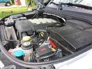
Winch Power upgrade319 viewsUsing 2 warn kits, and removing one of the wires to use on another project. The purpose was to replace the power and ground wire. I used Warn kits, which are 4/0 Welding cable. The original red #4 warped from getting a little too worn. The 2nd
Battery #1 Deka 9A94 AGM Intimidator, Battery #2 Deka 9A47 AGM Intimidator WARN 36080 28" Quick Connect Cable X 2, WARN 26405 Quick Connect Cable 7' X 2, WARN 15901 Black Cable X 1 -- winch control 72" X 1 https://www.facebook.com/DifferentialPartsUS
|
|

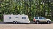
Lunar Ultima hitched to Disco 411 viewsPulling away for another caravan adventure
|
|

Anti Lock and Traction Control description and operation.1987 viewsNote on page 6 of this 17 page pdf the significance of the Steering Angle sensor mounted on the steering wheel shaft. The paragraph regarding the plausibility check as related to the brake pedal being not depressed is why the clean operation of the second set of contacts on the brake switch matters so much.
|
|

Steering Column detailing Steering Angle Sensor1497 viewsItem 2 in the picture on page 1 of the 9 page pdf shows the location of the steering wheel sensor. Page 5 of the pdf has a paragraph describing the operation of the sensor. When the steering wheel does not point the same direction as the real wheels, then the computers can put the 3 into safe mode and down goes the suspension. See also the 17 page pdf on the Anti Lock and Traction Control pdf.
|
|
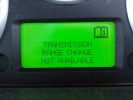
Transmission Range Change Not Available239 views
|
|
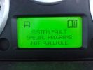
Special Programs Not Available231 views
|
|
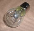
Land Rover Stop Tail Light dual filament bulb nominal 12 volt 21 / 5 watt filaments1427 viewsThis is the Land Rover part number 264590 dual filament bulb, (P21/5), that inserts into the upper two tail lamp receptacles. In the upper one, both filaments function, in the lower one, only the 5 watt tail light filament functions.
I regard it as not a good practice to routinely switch bulbs when the tail light filament, (5 watt), burns out on the lower bulb. The broken filament can jiggle over onto the brake light filament, (21 watt), and short the circuit to ground or something else not predicable.
There are also arguments to say that quality control is better on the Land Rover marketed bulbs than say far east sourced bulbs. Filament construction, and hence resistance can vary and mislead the current sensing circuits monitoring the signal light systems. Also when the bulbs are properly installed, all filaments should be standing vertically and not at any slope.
These are the sort of obscure circumstances that can lead to false trouble messages on the display, dropping to the stops, and subsequent concerns - all over a tail/signal light bulb.
For example, the filament life of both the tail light and the brake light filaments in the P21/5 bulb is significantly less than the USA common 1157 dual filament bulb, (1000/250 vs 5000/1200 hours); brightness in the P21/5 is a bit more, (3cp/35cp vs 3cp/32cp where cp is candle power), but current consumption is oddly less, (0.44a/1.86a vs 0.59a/2.10a where a is amps). It is the quest for efficiency vs maintenance trade off.
|
|
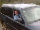
We could not shake him off,and he loved it141 views
|
|
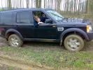
Well and truly stuck on a green lane at the weekend, there was a hill that does not show up in the photo!273 views
|
|
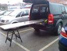
292 viewsNeeded 1.8m of worktop but had to buy 3m length. Took B&D workmate with me and cut it down to size in the car park! Notice how the workmate is exactly level with D3 in normal height!
|
|

2rmb24 views
|
|
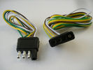
4 pin NAS flat connector from NAS small trailer382 viewsThe connector with the three exposed pins is the end that would commonly be located at the trailer hitch end, (front), of a small NAS lightweight trailer that has no electric brakes. This plug would connect into the flat 4 pin connector at the rear of the 3.
Note the order of the pin functions and wire colours: White is ground; the next pin is for tail/marker lights using the Brown wire; the Yellow conductor is for the left turn signal, and the far pin uses the Green conductor for the right turn signal.
There is no separate brake light conductor as NAS spec vehicles most often combine the brake and signal light functions to the same bulb filament rather separate filaments in different bulbs. The LR factory harness resolves that design difference.
Fortunately, the Land Rover NAS assembly pin order for the 4 pin flat plug maintains the above described conventions.
|
|
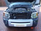
Reassembly225 viewsNote clean radiator!!
|
|

Air Distribution and Filtering Systems2084 viewsThis is 3 page pdf with coloured drawings of the air distribution ducting for the front air system.
Also included is a sketch of the pollen filter location within the front heater ducting. Note that two types of filters are available: a) the cheaper dust/pollen filter and b), the activated carbon filter that removes smells from the air. Installing the more expensive activated carbon filter means you never smell a cattle truck or chicken farm again. It really works.
|
|

Air Conditioner Specifications 4.4L V81570 viewsThis 2 page pdf is just the specifications for the AC system. The refrigerant type is R134A.
Note that when topping the system up, it can be a good idea to include some of that ultra violet light dye that will glow to show leaks and loose fitting.
|
|

Alternator and Regulator Wiring Diagrams, TDV6 and petrol V8 and V61989 viewsThis is a three page pdf that shows the alternator and regulator wiring for the petrol V6, petrol V8 and TDV6. The pdf can be either printed or by right clicking on the displayed pdf, rotated as required for viewing.
Of interest is that the regulator gets its instructions primarily from the Engine Control Module (ECM) and only secondarily from the vehicles electrical buss. The conductor from the battery thru the 5 amp fuse F20E is to provide initial power to excite the alternator at startup and then secondarily, to instruct it if the PWM signals were not available. Primary instructions to and from the ECM are thru the two other conductors via a digital like Pulse Width Modulated (PWM) signal.
If F20E, the 5 amp engine compartment fuse box fuse is blown, the red alternator light on the dash will be illuminated. This means that the alternator could be OK, but if the F20E fuse is blown, no electricity will be generated. Hence check the F20E fuse if you get a red ALT light or some indication of the alternator not working.
Regarding operation of the red ALT light on the dash, it is not the regulator within the alternator that tells the red light to illuminate, or not, but instead the ECM. This is the reason the red light does not function in the same manner as with older vehicles. With the 3, sometimes you have illumination and sometimes not depending upon what the ECM is thinking. What this means is that you can have an alternator that is failing but the red light does not illuminate as the ECM is compensating for reduced alternator output - maybe by draining the battery and or cutting back on vehicle electrical loads such as shutting off or cycling the radio amplifier or heated seats.
|
|
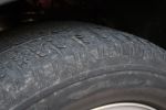
Pirelli Scorpion Zero after over 56000 Km133 viewsNotice the flaking.
|
|

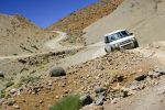
Shade is a rare commodity88 viewsRunning through the wadis approaching Jebel Achter, shade is a commodity scarce enough not to waste.
|
|
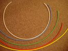
6mm Heat Shrink colours 362 viewsI decided to colour code the tubing so I used 6mm electrical heat shrink.
As there is no apparent colour coding re the 3, I tried to emulate the P38 coding; #1 LR red, #2 RR blue, #3 LF yellow, and #4 RF green. This was not doable as both left side air springs have green coloured tubing coming off the top of the front and rear air springs. I therefore arbitrarily chose the Left Rear to be red; Left Front green; Right Front yellow; Right Rear blue; and for the air compressor supply line, White coloured heat shrink. Since two new lines tie into each air spring line, I made the line between the air spring and the FASKIT, a single solid colour, and the line from the FASKIT to the valve block, White, plus the related appropriate solid colour.
|
|
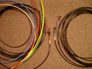
6mm PA12 grade nylon tubing with heat shrink applied 544 viewsShows some of the 6mm air line with heat shrink applied to one end of tubing. Shrink will be applied to the other end once field cut to length. These four tubes, each about 20 ft (6m) long, feed to the rear. Re the front air lines, (not shown), four additional lengths, each about 10 ft (3m) long, are required plus one more 3 metre length for compressor air. The 6mm tubing is a Nylon product specified as PA12. There is also a very similar Transport grade PA11 material, however it seems that PA12 is the more common Transport grade now in use. Also the applicable DIN standard seems to be both DIN 73378 and DIN 74324 for the nylon tubing. The working pressure of the 6mm tubing is about 27 Bar and bursting 82 Bar @ 20C. This is for the 1mm nominal wall thickness material, (4mm ID, 6mm OD).
|
|

Equippment attateched to player, nothing more30 views
|
|

11 views
|
|
Ham Radio448 viewsThe remote head of an Icom IC706 was mounted on a piece of wood shaped to fit into the coin holder. This is quite a tight fit and does not shake loose. The radio is mounted under the driver seat.
|
|
Cliff Drive235 viewsThe drive is quite steep but nothing to worry about!
|
|

The Vale of Belvior and Nottingham in the background58 views
|
|

Land Rover Aerial Fin images for both Glass and Metal Roof Disco3 / LR3864 viewsAs well as the two different fins, this pdf also shows the plastic blanking plate for glass roof vehicles where no fin is installed.
The glass roof fin is secured by two security screws from the top into a plastic frangible glue on gasket. The hope is that when struck, the fin will shear off and not crack the glass roof. Re the metal roof design, the fin is secured from underneath via two nuts.
The pdf also shows the various electrical bits related to the antennas. In the UK, the fin would house not only a cell phone antenna but the TV and satellite radio antenna electronics as well; in the States, the Sirius sat radio antenna and a G type cell phone antenna if the phone kit was installed would reside within the fin. The SAT NAV GPS antenna is located within the High Mount Brake Light plastic mounted to the upper rear hatch.
|
|

Fin cell phone aerial drawing190 viewsThe factory aerial for the factory NAV / GPS on my 2005 HSE is within the high mounted stop light lens at the top of the upper hatch door. I do not have the factory installed phone kit, and as such, do not have the fin installed; instead there is just a plastic blanking insert to fill the cell phone aerial wiring hole in the metal portion of the roof; hence this requirement for an "external" cell antenna. For those that do have the fin on their glass roof, the fin is screwed on to a glued on plastic gasket, (sort of), and not bolted thru as per the metal roof 3's.
|
|

Almost a Bridge10 viewsAnother bridge this one we had to rent the branches and use our sand ladders
|
|
Puncture repair13 viewsI think in total we did this about 10 times, in 6 months, not a bad record, but not easy in the Bush !!
|
|
Lunchtime Lane201 viewsNot 200 yards from Manchester Airport can be found a little 1/2 mile lane - did it for the first time today - a few minutes fun in a dreary day
|
|

182 views
|
|

Alternator female plug looking down into top373 viewsThis shows the plug connected to the alternator wiring harness looking down into the top of the plug.
The cavity marked 1 is the AS or BATT SENSE and the wire colour most likely has Brown/Green on it.
The cavity marked 2 is the RC or ALT CON and the wire colour most likely has Red/White on it.
The cavity marked 3 is the L1 or ALT MON and the wire colour likely has Green/White on it.
I say "most likely" as the wire colours are not always the same on all vehicles.
Also the terminal 1 conductor destination is more likely C0570-175 rather than per the jpg.
The #3 pin is located closest to the big B+ terminal.
|
|
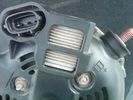
Alternator Plug and B+ terminal919 viewsPictured is the rear of the older Land Rover part # YLE500190 alternator showing the shiny cooling fin of the Regitar VRH2005-142 regulator under.
The first pin in the far left side of the connector is numbered #1 in the LR electrical wiring diagrams and is Battery Voltage Sensing (BVS); the middle pin, #2 receives a Pulse Width Modulated (PWM) signal from the Engine Control Module (ECM), and the right pin, #3 carries a PWM signal back to the ECM. Terminal Pin #2 on the LR wiring diagrams is called Alternator Control or ALT CON; Pin #3 per LR is called Alternator Monitoring or ALT MON.
Pin #1 is similar to what in older designs used to be called A or Batt, but is now called by Denso, S, AS, or Alternator Sensing for this design. Pin #1 also provides power to excite the alternator at startup until the PWM instructions over ride the battery voltage info. Land Rover calls the electronics under the pins a Smart Regulator, ironic, as it has to follow orders from the ECM rather than give the orders - new age thinking I guess. This is different from older design internal regulators that look at just the battery or the electrical buss voltage and then decides itself what to do.
It is almost like we are back to the external regulator designs of old, except that the ECM may decide that instead of telling the alternator to make more power, to load shed, and hence shut down the heated windscreen, seats, or whatever other electrical loads it decides are appropriate. My view is that the "smarts" are in the ECM and that the "regulator" should be regarded if not dumb, then as being a slave to the ECM.
|
|
Thread upload21 viewsImage uploaded in thread 176300
|
|
Android Note in Cubby3 views
|
|

Thread upload2 viewsImage uploaded in new thread
|
|

Thread upload9 viewsImage uploaded in thread 175029
|
|
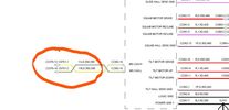
Thread upload13 viewsImage uploaded in thread 182362
|
|

Thread upload3 viewsImage uploaded in thread 172661
|
|

Thread upload5 viewsImage uploaded in thread 172661
|
|

Thread upload4 viewsImage uploaded in thread 46733
|
|
Thread upload0 viewsImage uploaded in thread 183818
|
|

Thread upload12 viewsImage uploaded in new thread
|
|
Thread upload5 viewsImage uploaded in thread 186931
|
|

Thread upload10 viewsImage uploaded in thread 186253
|
|
Thread upload6 viewsImage uploaded in thread 172661
|
|

Thread upload8 viewsImage uploaded in thread 187350
|
|
Thread upload9 viewsImage uploaded in thread 187502
|
|

Thread upload10 viewsImage uploaded in thread 187480
|
|
Thread upload4 viewsImage uploaded in thread 187851
|
|

Thread upload8 viewsImage uploaded in thread 142922
|
|

Thread upload14 viewsImage uploaded in thread 142922
|
|
Thread upload10 viewsImage uploaded in thread 187861
|
|
Thread upload10 viewsImage uploaded in thread 188373
|
|

Thread upload6 viewsImage uploaded in thread 188373
|
|

Thread upload10 viewsImage uploaded in thread 188373
|
|
Thread upload12 viewsImage uploaded in thread 188373
|
|
Thread upload9 viewsImage uploaded in thread 142922
|
|

Thread upload10 viewsImage uploaded in thread 188264
|
|

Thread upload5 viewsImage uploaded in new thread
|
|
Thread upload6 viewsImage uploaded in thread 142922
|
|
Thread upload0 viewsImage uploaded in thread 189220
|
|

Thread upload0 viewsImage uploaded in thread 189220
|
|
Thread upload0 viewsImage uploaded in thread 189220
|
|
Thread upload4 viewsImage uploaded in thread 172724
|
|
Thread upload1 viewsImage uploaded in thread 192740
|
|

Thread upload4 viewsImage uploaded in thread 193945
|
|

Thread upload2 viewsImage uploaded in new thread
|
|

Thread upload1 viewsImage uploaded in thread 196673
|
|

Thread upload1 viewsImage uploaded in thread 196673
|
|

217 views
|
|
Thread upload1 viewsImage uploaded in new thread
|
|
Thread upload11 viewsImage uploaded in thread 167398
|
|

Argentina - Taken by Alex, LRE.207 viewsCamp above Salta. No it's not dust on the lens!
|
|
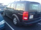
Got back to the airport after a few days in London to This!!!281 viewsThis is one of the many reasons we sold our first D3........
|
|
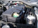
Aux Battery showing ground cable bolt "upside" down 1577 viewsIn order to obtain sufficient height clearance to get the plastic cover back on, I had to install the ground cable to the underside of the battery post connector.
Note the battery vent hose, (approx 5 ft required) is run down into where the windshield washer fluid container is located. There is not much electrical or metal in that area to be corroded by battery gas plus the open end of the vent hose tends to be protected from dirt and stays clean as well.
|
|
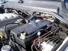
BCI Group 40R Deka 640RMF battery showing vent hose run forward to windshield washer reservoir area 1430 viewsRecessed post "Euro profile" battery to "match" OEM and stock Land Rover bracket; note that the Traxide SC80-LR module is mounted at an angle to allow for the main cable to sit under the cover so cover still closes.
The battery is a nominal 7", (180mm), high, but sits on a 1" battery spacer set under to raise the bottom front end of the battery such that the approx 11", (290 mm), length of the BCI 40R battery rises above the angled plastic nibs at the forward end bottom of the case front; hence sufficient space, (1/4", 5mm) remains at the brake reservoir end.
Also the 40R battery does not have hold down "flanges" on each end; on the sides yes, but not the ends so no additional length is required.
When I had to replace the 40R, this time I installed the shorter, (9.625"), taller, (7.5") Interstate BCI 47 / DIN H5 battery which eliminated the spacer on the bottom and better fit the stock LR tie down bolt lengths. Deka also has a BCI 47 / DIN H5 that would work fine as well.
|
|

me having fun702 viewsSorry, not LR related (other than I got there in the Disco)
Al
|
|

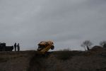
Back Flip not428 views
|
|
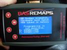
BAS remap interface after dealer software update287 viewsBAS remap interface after dealer software update,This is what you will be presented with after the dealer updates your cars engine software.
This is no problem IF you have returned the car to standard before the dealer visit.
When faced with this screen it will show you tht the dealer has changed the software and NOT let you put the BAS mapping back on your car because of the differences.
|
|
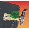
Battery Disconnect Wirthco 20308 Knob Top Post 890 viewsThis is a battery post style disconnect, usually for the negative terminal. There is a hole drilled in the round end off the battery so that flat terminal can be attached as well as the normal battery post terminal. I did not use this hookup arrangement, however I show it for information only.
|
|

Caterpillar Battery Size cross reference chart and battery profiles including post layout753 viewsThis pdf has a dimension, (metric and inches), cross reference chart plus another sheet that provides BCI and DIN cross reference numbers and shows post locations plus bottom ridge tie down locations, (or the lack of).
This data was for me, hard to find, and helps one in selecting a suitable physical size of Aux battery for the space available.
|
|
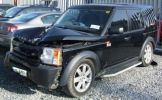
Bent Black Betty228 viewshard to believe that in this condition she\'s a write off, what got her was the cost of tricknology repairs, seatbelt pretensioners, airbags etc etc, & declining values, repair estimates €12500, value €13000. a no brainer really
Note TASTEFULL G4 sticker
|
|

156 views
|
|
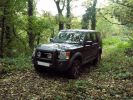
Another lunchtime excursion194 views
|
|
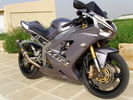
New Bike42 viewsGot bored not having my D3 with me so I went made one day and bought this!
|
|
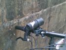
Another mounted camera - my Oregon ActionCam 200075 views
|
|
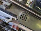
Buzzer located under black plastic cover.12 viewsThe white electrical connector clicks into the buzzer housing that is shown protruding from under the black plastic cover. There is a little tab on the white plastic that has to be squeezed to release the connector. In other words, do not pull on the two conductors.
|
|
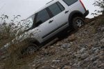
DiscoBlitzen comitted68 views
|
|

crankshaft bolt24 viewsBolt on left is new one for upgraded oil pump casing. Bolt on right is what came out. Notice damaged end and shortness of bolt. Inside of crank was inspected wirh borescope and threads etc all ok. New bolt goes in and out ok. Few filings inside but otherwise clear. Not sure why old bolt ended up like that.
|
|
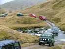
Another Highland 4WD Club Run. Boxing Day 2005, south of Inverness. We're in the second green 90.78 views
|
|
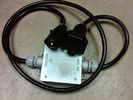
Box Closed with 7 Blade NAS connectors586 viewsBox closed up and ready for use. The box and cable connectors are reasonably weather tight and hence can be submerged for a bit while doing a creek crossing but as with the 3, do not use the creek bed as a parking stall. Similarly, the connector recessed into the bumper will probably remain somewhat dry as long as you keep moving but if you get stopped, well that is another story.
As such, I put a vial of desiccant in the metal box prior to closing it up to reduce corrosion due to moisture build up.
|
|
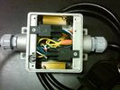
Box open showing Hella Relays and Putco Load Resistors749 viewsInterior of the box - note the two gold coloured 6 ohm 50 watt load resistors are a bit distant from the other items so as to provide some separation for dissipation of the heat generated.
Rather than a moulded plastic weather resistant box which I would have preferred, I used a bulky and much heavier metal weather tight style electrical box so the metal can act as a heat sink.
|
|

Black Deposits to interior of Brake Light Switch2862 viewsThere are two contacts, one on each side of the vertical plunger under the copper metal. The set of normally open contacts on the left side that carries the power for the brake light filaments, (15 amp fuse F15P), is apparently not heavy enough as the contacts deteriorate and generate the black residue.
The set of normally closed contacts on the other side appear to be sized OK. There is not as much current, (5 amp fuse F66P), flowing thru the contacts to the ABS module, however the contacts are likely adversely affected by the black residue produced by the other deteriorating set of contacts.
One presumes/hopes that the newer replacement switch now has contacts heavy enough to carry the brake light power. It would be ideal if the ABS set of contacts were sealed from the brake light contacts to prevent contamination of the normally closed set of contacts.
|
|

Brake Light Switch, Find, Remove, and Install Instructions 7854 viewsThis is a two page doc outlining where to find the brake light switch, how to remove it, and then install the new one.
Note, do not move the brake pedal when removing or installing the switch. Let the brake pedal hang where it wants to. The switch design is actually cunning, and as such is supposed to make the removal and install fool proof. Hence if you think too much about it, you can wreck the new switch.
If you want to inspect the interior of the switch, wait until you have removed the old switch. You can then just unsnap the blue from the white to get it apart. Inside, the switch is quite simple, (no circuit boards), but it will probably show black dust from failing contacts.
I think the reason the switch fails is that the Normally Open, (NO), contacts of the brake light contacts were made too light to carry the current load for make and break of the tail light filaments. I also think the black dust created then fouls the Normally Closed, (NC), second set of contacts for the ABS circuit. As such, the Normally Closed contacts become intermittent in operation and display as a fluctuating open and closed circuit condition to the ABS system when the ABS should be seeing a steady closed circuit. Hopefully the replacement switch contacts are more robust and may be as I recently replaced my switch again just as a matter of maintenance. While in a redesign, ideally the NC contacts should be sealed or at least separated from the NO contacts, when I inspected the removed switch, this time there was no black dust present.
Probably the removed switch will have a Land Rover oval logo moulded into it, the new one, FOMOCO.
|
|
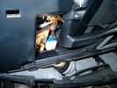
Brake Switch Visible thru Opening4975 viewsThe blue and white bit is the switch; the sort of gold appearing box,(it is really black), you will not see in your 3 as it is a Smooth Talker brand amplifier for my Blackberry phone antenna. This install is detailed in the SmoothTalker phone antenna section of my gallery.
One way to remove and install the switch is to lower the "horizontal" panel above the brake pedal as shown where the flashlight head is located. To actually remove the switch, you slide your hand thru the gap and rotate the switch clockwise 1/4 turn while watching thru the rectangular opening. Installation of the new switch is the reverse of above - 1/4 turn counterclockwise.
Before you remove the switch, note its orientation - horizontal with electrical wires to the left. That is the way it should look after replacement as well.
The second time I replaced the switch, I did it all thru the rectangular opening and did not remove the horizontal panel - that is experience helping out.
The knee kick you have to remove regardless. It is sort of hinged at the bottom so you just pull at the top and sort of rotate the knee panel and then pull upwards for two plastic "fingers" to clear the slots they reside in.
|
|

Black Deposits on Brake Light Switch Plunger2758 viewsThis jpg I got off another forum and is typical of what one will see when one opens up the removed brake light switch. The black powder is residue from arcing of one of the pair of contacts within.
Hopefully the newer switches with the FOMOCO logo moulded into the plastic are improved from the Land Rover logo marked early units, however I doubt it.
The Ford part number is SW-6572 and/or 7E5Z-13480-A as used on the 2006 to 2009 Ford Fusion's and Mercury Milan's; the Land Rover part number is XKB500110. Cost of switch could be about twenty five dollars. A previous LR part number for the switch was XKB500030, so hopefully the newer LR part number, XKB500110, reflects some improvement in reliability.
It is possible that the new switches are better as I installed a replacement 72,000 km, (45,000 miles) later, at 195,000 km (121,000 miles). When I took the removed switch apart to inspect, it was clean inside. There was no black dust - the switch looked like new, hence they must be improved now.
|
|
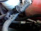
Breather line with factory cap cut off.2320 viewsIf you expand the jpg by clicking on it, in the bottom right corner if you look closely, one can see the black plastic factory vent tubing with the OEM cap cut off.
Note the tubing is cut at a 45 degree angle facing to the rear. Also shown in the top right is the cut off portion sitting on the coolant water hose and on the top left also sitting on the coolant hose, the new to be installed Gore manufactured replacement breather cap.
|
|
Vertical Breather Hose before cutting off OEM cap.1779 viewsThis shows the plastic vertical breather tubing and OEM cap prior to being cut off. The tubing is located on the driver side at the front near the radiator. One cuts about 3/4" to 1" off from the top. The TSB says 20mm.
I tried blowing thru the cut off piece and was not very successful. The cap seemed plugged. I am beginning to think that there was a very good reason for Land Rovers's Technical Service Bulletin, (TSB).
|
|
Can Pair Repair84 viewsThis is the high speed CAN bus Pair. By over twisting and keeping the repair short i will maintain the very important twist. Good soldering is a must it looks ropey in this shot but it is not, note the heat shrink pre placed on the wires to the right.
|
|

47 views
|
|
Elddis Crusader Storm256 viewsNot our actual caravan (or car) but very similar! We have a Superstorm which doesn\'t have a fixed bed at the rear like this one does.
|
|

Saw this TD5 on eBay - note the bonnet scoop and roof spoiler...318 views
|
|

137 views
|
|
Disco and Boroma with Hyland hitch fitted inverted.153 viewsNote that it is now absolutely level.
|
|

car audio technics leaflet but they quote £600 or something, not the price on here238 views
|
|

Central Door Locking Operation Description1458 viewsThis 17 page pdf explains how the door locks are supposed to operate. Note that on page 9/17, the explanation of the operation of the hood ajar switch is wrong. It operates similar to the door and tailgate ajar switches; that is when a "door" is closed, the switch is closed to maintain a ground back to the CJB. Opening the hood, door, or tailgate removes the ground breaking the circuit and hence allows for an alarm condition.
|
|

Thread upload9 viewsImage uploaded in new thread
|
|
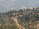
not a rice field in sight31 views
|
|
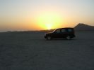
Sunset on Mazirah100 viewsOur camp site for the night - nothing but us, sand and green turtles. Fabulous view out over the Arabian Gulf, blue skies, blue seas and isolation. Almost paradise.
|
|
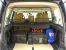
Load space369 viewsShows the SA Front Runner Wolfpack stacking plastic storage boxes that I keep laod straps etc in and the 2nd is tool kit, spare belts, jerry can funnel and tools, plus airline and tyre inflator/deflaotr for ARB on-board compressor, HD jump leads. ARB Winch pack (Orange)with strops, snatch blocks, shackles, gloves, and 2 ARB recovery dampers. Really great 4x4 1st Aid kit from Outdoors warehouse in SA. LRs own loadspace guard - not the best design if you want to store a long load. Mods to be carried out!
|
|
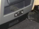
Auxiliary power sockets - TracTronics, Australia383 viewsA complete kit including two outlets, wiring etc connected to auxiliary Optima Blue top battery using their very effective SC40 split charge relay. One outlet between rear and front seats, and 2nd alongside loadspace 12v outlet, enables fridge to run when engine is not running, without affecting start capacity or vehicle functions.
|
|
TracTronics loadspace power socket 382 viewsThe 2nd power socket fitted alongside the original in the loadspace runs off the auxiliary Optima Bluetop battery to run a fridge when engine is not running. No more starting worries!
|
|
LongRanger auxiliary fuel tank358 viewsThe LR fuel tank imported from ARB in Australia with its 115 litre capacity has more than doubled the range of the car. This is important in the desert where fuel consumption increases at times to 10mpg or less. On a cruise on highways, the car now has a range approaching 850 miles. The tank fits neatly, has not affected handling in a detectable way apart from over speed humps, when a little more bounce from the rear suspension is detected! Suspension copes with the additonal loads without any problem.
|
|
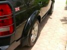
Body-matching wheelarches250 viewsAnother shot of the body-matched wheel arches, sills and door mirror bodies.
|
|

Not a pretty picture93 viewsWell, there had to be one of the beaming owner in the album somewhere.
|
|
Thread upload15 viewsImage uploaded in thread 201071
|
|
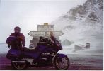
10,000ft up in the Alps!!! Honda Pan European Sept'01393 viewsThis was the first time I had ever fallen off a bike. Snow didn't help! Nothing hurt or damaged so we stopped to take a picture...
|
|
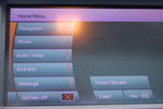
Colours not Correct60 views
|
|
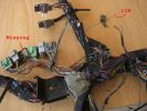
example problems113 viewsInspection showed another Cut Airbag connector, a Missing connector and a few rogue wires at the bottom, the silver one marked Lin, is for the LIN BUS and is supposed to be like that though
|
|

COOPER ST, standard size.460 viewsPretty good all around. A bit noisy compared to stock tyres but nothing compared to a Defender or a Disco 2 !
|
|

Mengel Pass110 viewsAnother moderate section.
|
|
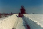
the road between home and work292 viewsthe day before returning from work, I got stuck here in the middle of the snow storm. The plow didn\'t pass yet and wind was blowing snow everywere. Since then I always carry during winter a survival pack consisting of warm coat,cap, warm, high boots and gloves.
It is no fun recovering a car stuck in the snow and sliding down from the road when moving in nothing more than a business outfit (no gloves, city shoes, no coat) with a snowy wind blowing 100km/h..... .
|
|
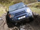
Not getting further #2332 views
|
|
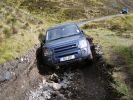
Not getting much further306 views
|
|
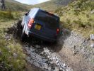
Not getting further #1303 views
|
|
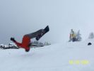
Backflip (not)409 views
|
|
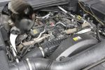
Engine Cover Removed901 viewsView of the engine before blanking off the EGRs. The inset sort of shows one of the EGR valve/pipe flange securing bolts. The EGR valves are not easy to get at!
|
|

Not much left of bonnet!281 viewsCrash in a Renault Scenic
Head on colition with a Nissan Terrano he lost control came over the central reservation & ended coming at us sideways!
We hit him in the back wheel arch & spun him around so he then hit my drivers side, I walked away having a air bag wife had broken solder coursed by the seat belt, but it did save her life!
Our car was trashed but it did its gob (was only 2 weeks old!) the bonnet tacking lots of energy out of the collision & the inertia staying relatively in tacked.
|
|
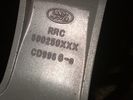
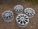
Part number moulded into spoke of 18" ten spoke. 322 viewsThis part number, RRC500250XXX is moulded into the backside of one of the spokes of the ten spoke 18" wheel. An alternate part number is ALY72190U or ALY72190U85 which relates to year and finish.
Another number is RRC500250MNH where MNH is also the finish, probably Sparkle Silver.
|
|
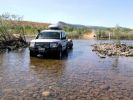
D3 in the Kimberley - on the Gibb River Road, crossing the Pentecost River49 viewsNot too far in on the Western end of the Gibb River Road is the Pentecost River, with the ranges in the back ground - an iconic shot of the Gibb River Road.
|
|

C pillar cover removed to facilitate removal of bin cover.9 viewsNote the "ribbon" behind the top left corner of the C pillar cover. This is something to do with the curtain air bags, hence do not mess with it. I dislodged the cover to make it easier to pull up and extract the black plastic bin moulding. It is not necessary to totally remove it and would be what I call a big deal - seat belt, air vent and ducting as well as that curtain concern.
|
|
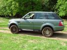
Not all bling, they do get dirty now and again429 views
|
|

doh believe it or not but i think i know what happend no special program selected50 views
|
|

not making progrees48 views
|
|
dicky just about to not make progress61 views
|
|

dicky still not making progress51 views
|
|

Dicky not putting enough effort in to this recovery57 views
|
|

at least you are not alone biskit61 views
|
|

Simon on for another clear round60 views
|
|
V8 4.6 71 viewsD3 completed a down run & not to be out done 90 completed an up run in grand style
|
|
453 viewsMore photos coming soon. 7000 km with NO problem. Only took a 6th spare wheel, a tool box, air compressor, window shades. What a great Disco !
PS: note that my disco has manualy inflatable air sping in addition of the standar terrain response.
|
|
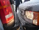
Taken from behind in the snow!!!322 viewsNot sure who bumped me..... but my car was being serviced at the time and this was a courtesy car!
|
|
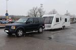
d3andvan153 views
|
|

Fuel Burning Heater Install Instructions (not mine, sorry)576 views
|
|
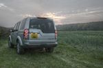
Evening drive in Nottinghamshire183 views
|
|

Propshaft Support - Front view46 viewsNote the quality Sikaflex instead of the pathetic fragile rubber. :-)
|
|
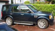
Lugano Teal713 views
|
|

Thread upload1 viewsImage uploaded in new thread
|
|

Per replacement of seat base foam - note creasing on right side due to collapsed foam40 views
|
|

Thread upload1 viewsImage uploaded in thread 207981
|
|
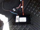
D4 Bluetooth AH42 10F845 AA module connected to 12VDC and MOST1210 viewsThis jpg shows the MOST bus connected to the AH42 10F845 AA module used in the D4 as well as +12VDC power from F58P connected. The power is split with a Y harness as the IHU (radio) for some reason required +12VDC power to the C2115-10 "mute" pin to keep the radio/CD audio from muting all the time.
With power on the pin, the radio audio does mute as it should when the cell phone rings and the hands free connects. The brown conductor feeds to C2115-10 and the blue to the module.
The module tucks up and hides behind the grey plastic section covering the forward portion of the passenger side tranny hump for left hand drive vehicles; for RHD, it would be located on the left side.
The pairing code is 2121 with this setup and not 1234 or 0000.
|
|
Discovery 5 preview131 viewsQui si vede Panoramix e Piadina sulla nuova D5!!!
Notare i cerchi con gomme super super ribassate (neanche le vedi dalla sottile spalla che hanno!)
|
|

Defender in the Fog, another day on the job.459 viewsThis is another normal work day for a Defender - actually the jpg is from a Land Rover advertising shot, but it may just not be a set up one. I think it is an actual working Defender. Note the visible front tow hook and how the hi lift is just rope tied on; also the normal stock headlights and I guess dual spare tyres - just another day on the job.
|
|

Deka Battery Dimension Data615 viewsThe battery size that I installed for my auxiliary was a BCI 40R battery as it was for me the easiest to fit and was also a cranking battery. The case profile was such that no tie down fins were located on either bottom end, (sides yes), and length wise, it was only about 11" (290 mm) long. As such, I did not have to grind the nibs at the front bottom of the plastic surround.
I did however raise the bottom of the battery above the angled nibs as I set the battery on a 1" (25mm) high plastic spacer. The total height, (battery plus spacer), was about 8" (200mm) so the battery top still fit under the Land Rover factory cover.
For the Aux battery, when I replaced the 40R, I installed an Interstate BCI 47 which is similar in size to a DIN H5. I was therefore able to eliminate the vertical spacer as the Group 47/H5 is the same height as the DIN H7/H8 stock LR spec starting battery. As such, the standard battery tie down bolts can be used without modification. The Group 47 battery is 9 11/16" long x 6 7/8" wide x 7 1/2" (190mm) high.
|
|

36 views
|
|

Difflock225 viewsDifflock with annotations
|
|
The Old Girl - Not the Wife!191 views
|
|
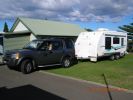
Another photo of the D3 & caravan outfit ... this time using the Mitchell Bros towbar and Hayman Reece WDH (May2008)126 views
|
|

NEW REG PLATES29 viewsHi Guys,
I would like to buy these plates. they dont seem to sell them in the shop. Does anyone have any problem with me using the disco3.co.uk on the bottom of the plates. id rather do this as i do not want to add any stickers to my car.
d
|
|
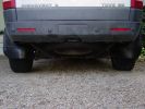
Modified Mud Flaps on Disco307 viewsNot Beautiful, but...............
|
|

115 views
|
|
107 views
|
|

the ole 96 disco on one of several 4000 mile road trips. In Colorado here with a another Land Rover behind176 views
|
|
109 views
|
|
109 views
|
|
Me fording in Grosmont381 viewsMe have a splash in aford at grosmont north yorkshire was only 18 inches deep nothing big.
|
|
sticker161 views
|
|
101 views
|
|

106 views
|
|

105 views
|
|
107 views
|
|

109 views
|
|

106 views
|
|

Thread upload10 viewsImage uploaded in thread 176264
|
|

discowex nearly making it... after barryg... but not quite122 views
|
|
RRS wheels with Vreds not included31 views
|
|
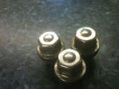
Nuts to you sir?25 views5 not just 3
|
|
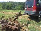
LR3 to plow your garden298 viewsI found this jpg where a current LR owner is using his LR3 for a similar purpose as the original Series units were designed to do - that is serve as a tractor for plowing a field or I suppose a garden.
In this case, I note the hitch is one of those that attach to the factory tow loop, (Rhino Hitch), rather than the factory product that inserts from the bottom and hangs down - (like a plow), but all the time. One of the other jpg's in this album shows the two factory variations plus a third jpg shows a closeup of the Rhino Hitch.
|
|

05 plate disco47 viewsover 120k on the clock leather damaged, guys wanted over 12k, said it had full farnell dealer service. mmm i think not, as checked
|
|
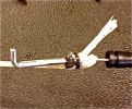
Pull cord as a backup63 viewsI added a pull cord so I would not kept caught with a broken release on the tailgate again. Think about a flat tyre if that happens to you.
|
|

Thread upload12 viewsImage uploaded in new thread
|
|

\'Our\' Zara with 60 Anniversary model490 viewsNot the most flattering photo of her.....
|
|
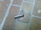
Small rod broken, note the small locking pin broken also169 views
|
|

me with nothing to do on a DSV103 views
|
|
Right fog uses H9 bulb, note the difference between the H11 and H9 bulb253 views
|
|
Right fog uses H9 bulb, note the difference between the H11 and H9 bulb243 views
|
|
Right fog uses H9 bulb, note the difference between the H11 and H9 bulb227 views
|
|
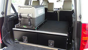
Ironman Drawers and Fridge Slide112 viewsI hate kitsets, over 100 bolts to assemble this unit and lost gallons of sweat, must have read the instructions a hundred times or more but final product does not look so bad. A few bolts hanging out the sides of both slide and drawers that may catch things so time will tell if I made the correct purchase.
Maybe one day I will make some side wings to cover the sides properly.
|
|
Another Toy140 views
|
|
another picture of the direct feed from the headlight163 views
|
|
Again just another pic of the wiring into the main175 views
|
|
Disco 3's in the Serengeti? not quite.328 views
|
|

Yer name's not down, yer not commin in...271 views
|
|
68 viewsrainsensor as seen from outside. Note tinted film around sensor
|
|
Sump guard, note drain holes to rear454 viewsThe sump guard runs back to the crossmember, it\'s a good idea to drill some large - ish drain hiles as there is no way water and mud can escape once it has entered round the revovery point
|
|

Entry to another cave in the limestone58 views
|
|
Simon on another hill360 views
|
|
Yet another use for side steps...275 views
|
|
Screen profile437 viewsNote that the passnger airbag is switched off when the screen is fitted - no problems to date with solar gain on the rear of the screen
|
|
Solo screen mount490 viewsNote that the mounting bracket doubles as a screen mask
Mount is Manfrotto \'super clamp\' & arm
|
|
Amber strip light, note hotspot289 viewsShould be better with a 3W lamp
|
|
Not the FR rack, but what was left of the Land Rover rack after a door incident218 views
|
|
Not the FR rack, but what was left of the Land Rover rack after a door incident182 views
|
|
Not the FR rack, but what was left of the Land Rover rack after a door incident151 views
|
|
Not the FR rack, but what was left of the Land Rover rack after a door incident173 views
|
|
Crossing the bridge across the ruacana falls, just past the border post into Angola173 viewsWill - a chef of note, and a great companion. Kept us well fed, and well entertained
|
|

Disco 3 not available, so had to tolerate this awful £60k RRS instead :-o237 viewsOnly the half-day introduction course, but Geordie was an excellent tutor and we had an amazing time.
|
|
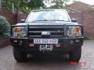
ARB335 viewsARB Bullbar and Warn tabor winch, with detachable tow ball(not installed).
|
|
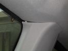
C pillar trim224 viewsnote gap
|
|
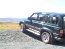
My old Landcruiser183 viewsApart from a battery and an exhaust I spent nothing on it.
|
|
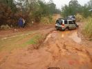
mud recovery221 viewsI think this is atacama in the poo. Heine is out of the picture to the extreme left. Note the white recovery rope stretching out of the frame
|
|
The "alternative route"161 viewsThis was the start of the rocky bit that cut out the snotty slopes. Wasn\'t the way to go unless you quit
|
|
Not so new any more...479 views
|
|
90 viewsRear of car, note control? box just behind and above rear diff
|
|
Does Not Apply to D3s237 views
|
|
Remote wires tinned - I did notice the red also needed re-doing!!!!47 views
|
|
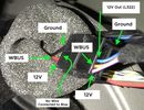
W-Bus out cable in pin 2 (NOT the same cable going to ground!!!)80 views
|
|
Notice the flame - IT WORKED!!! first time too, lovely!98 views
|
|

...alternative grommet threaded through (but not cut)...67 views
|
|
1st day river crossing. Note the steep rocky track the other side.92 views
|
|
packing up to leave, note short suspension hieght rods not removed yet123 views
|
|
229 views
|
|
The old, broken one124 viewsNote the gap between the end of the Bowden cable and the place its meant to be....
|
|
Another red rag...298 views
|
|
Side views not distorted (much!) 302 views
|
|
Spare connectors?312 viewsOK - nothing to do with reversing camera - in the wrong gallery :(
In Tow Ball storage side (D4)
|
|
The Road I came up.333 viewsThis is the road which caused my problem, drove up it, not realising there was a T junction which I had to turn right, turned, but could not get myself to get off the brakes and accellarate, so went straight on down a ditch!
|
|
Yup, Im Stuck492 viewsIt does not look too bad, but the front pass wheel is in the ditch (no contact) the other fron wheel is on mud, the pass rear weel is in an \'ice pack\' and the other rear wheel is at full extension and not gripping.....
|
|

Another view50 viewsA view of the general area showing the damaged part, lower centre. The second occurrence shows similar damage.
|
|
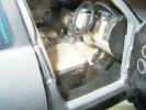
V8 HSE Auto Reg 734 EAB367 viewsThis is the model D3 that everyone's got.
Ever noticed that although its a V8 auto, it's got a clutch pedal??
|
|
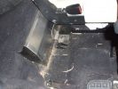
Internal water tank right side view162 viewsShows right front side of tank, with RH seat lifted. Note seat bolt is used to also hold the tank secure. This is a 5-seat D3, which has a cover over what is normally the 3rd row footrest. This is where the water tank is located.
|
|
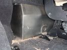
Right side floor-level view of water tank.151 viewsShows tie-down bolt (one of 2 securing the tank). Also note small void on side, which permits tank area to dry out if accidentally overfilled.
|
|
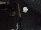
Internal 40 Litre water tank - top view of left side of tank106 viewsShows my spare tyre, but also bright white protective cap of top fill point and vent. Blue hose is water dispensing point. Note seat bracket bolt secures tank to D3. Similar bolt point on other side. Only these two bolts secure the tank and it is very secure.
|
|
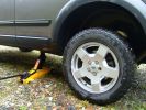
399 viewsNot my prefered method of jacking. Way too unstable,
|
|
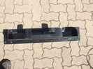
Top view of "Uncle Ray" discrete winch tray, after painting.107 viewsNote that towards the upper right there is a notch in the tray. This is needed for the specific winch's electric solenoid. The winch is a Mile Marker 12,000 lb hydraulic unit.
|
|
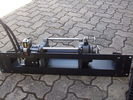
Hidden winch mount with winch in place125 viewsHydraulic hoses are now installed. Note notch for hydraulic:electric solenoid to fit in mount.
|
|
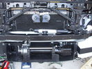
Front bumper view of semi-installed winch121 viewsNote the left-side (looking forward) bracket holding the white windscreen washer bottle.
|
|
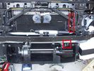
Installed winch with hydraulic hoses178 viewsThe hydraulic hoses are stiff, so I had to run them up the side of the radiator (can just see inside red boxes) to near the top of the radiator, then back down inside the engine compartment, then underneath the engine (behind the radiator) to the D4's power steering rack, where the hoses become metal. This hose routing may not be possible if the fuel-burning heater is in place (we don't have those in Aust and the space allowed room for my hands to bend and run the hoses without kinking).
|
|
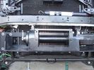
Close-up front view of partially-installed winch121 viewsNote that the sheet-metal flange just above the winch had to be notched to allow winch controller to be actuated. Also this same bracket had to be bent upwards to allow the winch hydraulic:electic solenoid to fit without rubbing. The nut on the upper-left bolt (the one with a very faint circle around it) stripped on re-installation, so the tray and winch pulling load is held only by the threads on 7 bolts....
|
|

Photo showing inside sock.166 viewsThere is a double layer inside. Just like a conventional tent, the waterproof layer, then a flysheet. Both can be zipped/unzipped when vehicle is not in place.
|
|
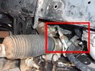
Detail of hydraulic hoses attached to power steering hoses155 viewsHoses are attached to the upstream side of power steering rack. When winch not running, PS rack sees full pressure (ie, no change from design). Biggest challenge is running stiff hoses so that they align with attach points. I got Qantas employee who repairs hydraulic baggage loaders to braise in fittings (very tight spaces and tough access).
|
|
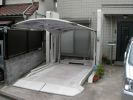
Car parking Japan style! (not sure its Disco sized or rated though...)143 views
|
|
498 viewsRear iPod cabling solution. Notice the hole where the cables descend into the rear of the center console.
|
|

400 viewsCloser view of leftside impact absorber. Note the thin piece of plastic I placed between the absorber and the cooling system component. Note air suspension hoses covered by protective tubing at bottom of photo.
|
|
273 views
|
|
TG vandalism ...... not guilty, just recording the evidence191 views
|
|

HAmsters landrover 2159 viewsAnother view!
|
|
Ness's humps33 viewsI am pretty sure I split my mud flap here. still they are still attached to the car - this is one thing the wife did not spot ;-)
|
|
45 ers 228 viewsagain, picture does not do the angle any justice. getting out of the car was pretty difficult. great pay and play site
|
|
45ers - 31 viewslooks tame, but the car was at a pretty extreme angle. picture does not do it justice.
|
|
182 viewsAnother shot of the right slider. The center support channel has drainage channels welded in that match the locations of the drain holes on the sill frame.
|
|

Waznotwas86 views
|
|

Waznotwas82 views
|
|
WasnotWas96 views
|
|
WasnotWas104 views
|
|
WasnotWas91 views
|
|

WasnotWas102 views
|
|
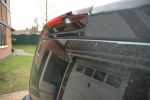
486 viewsreally not visible in the rear screen
|
|
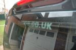
disco 3 stickers489 viewsnot visible thru the privacy glass - doh!!
|
|
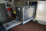
built fridge slider in front door (as opposed to rear) which makes fridge available at the kitchen. Also added drawer for gas stove - stows easily under the fridge when not in use. can be used independantly of fridge, ie. whether fridge is pulled in or ou116 views
|
|
fitted stronger rear strut holders. not a great mod. the holes i drillled for the "R" clips are the best mod, as they stop the legs from sliding up under pressure. requires bracing inside to stop chassis bending103 views
|
|

another shot of phone coax connector298 views
|
|
44 viewsOur old D3 with the carashack, traded in but not forgotten.
|
|
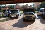
Not often you see a bunch of D3\'s with their bonnets open!162 views
|
|
DSL Dangling a wheel188 viewsOops, at least it was the uphill side, not the cliff side!
|
|
tomtom go 910 in situ, oriented to the driver742 viewsit pivots either way - not the custome landy screen which is bigger then the other tomtom models
|
|
It does NOT look like a van!841 viewsBrand new, just delivered.
|
|

149 viewsThis is a JPEG Taken from the CAD drawing, it has nothing to do with NEXT BASE OR LAND ROVER,FORD TATA, its just a FUN Model and not to be used.......
|
|

D pillar speaker cover removed to facilitate removal of the bin cover.11 viewsThe pipe thing exposed when the D pillar cover is removed is something to do with the side curtain air bags and hence is not to be disturbed - at least my me. Removal of the cover make lifting of the bin cover easier.
|
|

Thread upload18 viewsImage uploaded in new thread
|
|
EGR Valve/Pipe Flange896 viewsThe bolts in the inset are the ones to be removed. Note the rag stuffed down beside the EGR to prevent dropped bolts or gaskets disappearing for ever. Don\'t forget to take the rag out if you don\'t want your D3 to go up in flames next time you use it!
|
|

216 views
|
|

Pictorial instructions on EPB bedding in mode524 viewsDriving and reading LRs instructions is not easy - I tried this in graphic mode - MIGHT help
|
|

Thread upload1 viewsImage uploaded in new thread
|
|

Thread upload2 viewsImage uploaded in new thread
|
|

eye test 126 viewsLook at the picture below very carefully
Have you noticed the girl in the background?
Can you see her bum?
If your answer is YES then go and see an Optician!
What you see is the armpit of the girl taking the picture.
|
|
Socket found attached inside the grille - behind the LR badge51 viewsThe socket was attached behind the grille - and connected but to what I do not know
|
|
CALENDAR 2008 ENTRY633 viewsAnother ship wreck, this time in Chile
|
|
Slimer demonstrating his prowess with his airbag!266 viewsneo was inspecting the underside at the time - not sure why?
Allegedly a 4 ton airbag was needed since the boot was full (and I can confirm this) of crates of Desperado
|
|
ZZR 60054 viewsAnother photo of a mates bike i painted for him.
|
|
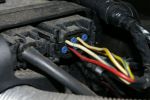
FBH connector on my 3 year old "S"150 viewsNote existing wire on 2nd row, pin 2.
|
|

Thread upload13 viewsImage uploaded in thread 187407
|
|

Thread upload9 viewsImage uploaded in thread 207388
|
|
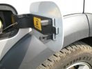
Filler Cap50 viewsNotice missing bit...
|
|
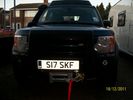
winch fitted at home in about nine hours 242 views
|
|

Fluid, Filter/Pan Combo removal and install5980 viewsThese are the LR instructions re removal and install of the plastic pan/filter combo for the ZF 6HP26X transmission on the 4.4L petrol V8 LR3.
The instructions tend to ignore the reason you have to lift the right hand side of the engine about 40 mm. This is because of a frame cross member that interferes with dropping down of the plastic pan. The real problem is a vertical "oil filter spout" that rises out of the filter/pan combo up into the transmission. The spout is the suction pipe for filtered transmission oil back up into the tranny.
On the metal pan versions, the filter is separate from the pan, hence the filter remains with the tranny when the metal pan is dropped. The filter is then removed or installed independent of the metal pan, hence with the metal pan, there is no need to lift the engine.
If one is removing the plastic pan so as to install the metal pan, then some do not lift the engine but just drop the plastic pan enough to gain access to saw off the vertical plastic spout - it is a one time procedure.
Be aware however that the metal pan uses a flat gasket and the plastic pan uses a O ring like perimeter gasket that sits in a half round groove in the tranny casing. Also the metal pan uses 21 shorter torx M6x22.5 metric cap screws for the perimeter bolts. The plastic pan uses longer M6x28.5 torx metric cap screws.
|
|

Thread upload2 viewsImage uploaded in thread 198799
|
|

footwell - another angle170 views
|
|
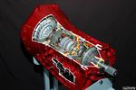
Ford 6R60 six speed cutaway showing torque converter.2198 viewsThis is a cutaway of the Ford 6R60 six speed which is a Ford license built version similar to our ZF 6HP26 six speed speced on early 3's.
The newer 3's and 4's have the ZF 6HP28. The Ford version is called the 6R80 and variations of it are used on the Raptor. As such, the Raptor metal pan can be installed on the 3's tranny but the deeper Ford Raptor pan does not have a drain plug.
|
|

Ford Sounder 4L1Z-15K864 A that I installed.12 viewsThis is the Ford sounder, part number 4L1Z-15K864 that I purchased and installed in lieu of the official Land Rover sounder. Note the part number is what is printed on the box (and also my invoice) but the part number on the sounder body is a bit different. I think a new box/invoice related part number is created each time the price of a part is changed. Regardless the Ford sounder was about half the cost of the Land Rover part and sounds the same as the removed factory buzzer.
|
|
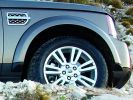
Split 7 Spoke on 2010 Discovery 472 viewsI noted that the tyre image has been flipped but the LR badging on the air intake is right way around. Interesting
|
|
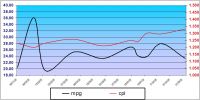
MS Excel chart of fuel usage in TDV6 first 3 months of ownership201 viewsReason for distortion at beginning is not known - average so far is 11.55l/100k (25.09mpg) for the 6 199k travelled. The fuel usage 'bumps' correspond with the city driving although they did mirror the cost for a while! A copy of the spreadsheet (105kb) that shows MPG and l/100k (but not miles) is available for the asking - just PM me.
|
|

Series LR at Oil Sands Plant in Northern Canada circa 1968747 viewsThis is an end of shift picture taken about 1968 at the Great Canadian Oil Sands (GCOS) plant while under construction in the Ft McMurray area of Northern Canada.
I was surprised to see the yellow coloured Series single cab hardtop pickup parked in about the centre of the picture. I would say it is one of the few on site as most vehicles were Chevrolet's, (as are the other three trucks elsewhere in the view). The yellow painted vehicles including the Land Rover are most likely Bechtel owned - not leased - yes, that long ago now.
|
|
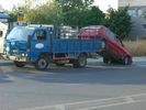
45 viewsHow not to have someone deliver your Golf
|
|
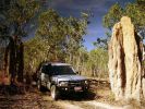
D3 in Kakadu National Park, on the track into Graveside Gorge51 viewsKakadu National Park is in a World Heritage area, with the entrance about 3 hours out of Darwin. It took another hour to get to the un-marked track into Graveside Gorge, which then took three hours to travel the 41km in. Not a tough track, but a series of big wash-outs with very deep and soft sand in the creek beds made driving fun. The most amazing thing, was that we had the whole place to ourselves. No marked tracks, so bushwalking involved blazing a trail using GPS and topo maps to find the way.
|
|
27 views
|
|
26 views
|
|

The Hooligan!144 viewsBefore you ask, no she's not a husky - she's a White & Champagne German Shepherd Dog.
|
|
Look Dad.. not sure mom\'s gonna make it?116 views
|
|

Thread upload17 viewsImage uploaded in thread 144929
|
|

Hibernot book cover14 views
|
|

Hibernot book11 views
|
|
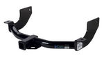
Curt Manufacturing brand hitch, assembled but not installed.290 viewsThe Curt Manufacturing hitch is an alternate to the Land Rover removable "plow" hitch. Once bolted in place, the Curt hitch is always there.
The Curt part number is 13456. It is a Class III hitch with a 2" square receiver and designed for a maximum 600 pound tongue weight.
The hitch hangs below the rear bumper but does not stick out past the bumper; also the "donut" spare tyre can still be installed / removed; am not so certain about a full sized fully inflated spare.
|
|
Rhino Tow Loop Hitch270 viewsThis is a receiver end view of the Rhino Hitch that ties to the factory tow loop. In addition to improved strength, it does not reduce ground clearance as does the factory style when installed.
Land Rover in early advertising videos when the 3 first came out showed the D3 hanging from a crane via the frame. The intent was to show how strong the frame is and by inference, the rear tow loop, specifically noted as being good for 6 tonne. The video ends before anything dropped or was lowered back to the ground, so one of course does not know for certain. The Rhino Hitch design however picks up on the apparent evidence of strength and certainly the additional clearance.
|
|
Thread upload5 viewsImage uploaded in thread 207039
|
|
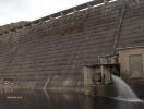
Another Dam .. Big one155 views
|
|

Another spooky looking place ?174 views
|
|

Thread upload4 viewsImage uploaded in thread 159579
|
|

Thread upload3 viewsImage uploaded in thread 159579
|
|

not in a good place....74 views
|
|
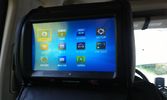
One of the multimedia headrests14 viewsI used to have seperate touchscreens mounted on the headrests.
I now went to the xtrons 9" headrests which gives the children the possibility to
- view whatever movie they want to
- listen to whatever music they want to
- play whatever 32native game they want to (although I'm not quite happy with those)
and they can do this no matter what the other one is doing :)
|
|
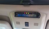
Battery check display15 viewsI mounted a digital battery display in order to see the voltage on the auxiliary battery.
There's also a thermometer which gives the inner and outer (via a side switch) values.
The display is switched on/off via another rocker switch.
|
|
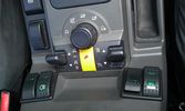
The on/off switch for the battery display22 viewsThe right inner switch 'powers' the auxiliary battery display. I might use that one to power on/off the driving camera (which will be arriving soon) as well. Although I'm not sure yet.
|
|
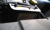
Solenoid not yet engaged18 viewsWith the engine running, the counter in the solenoid starts running and the green light blinks until the timer hits 5 minutes.
|
|
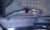
56 viewsThe OEM 2 ISO harness. Notice the red and yellow, which are important for my radio. Not having the red connected simply didn't activate the radio (so I wonder what the radio does with the permanent 12V)
|
|

64 viewsAdded a lead coming from the 12V outlet in the front console. That one is activated only when the ignition is set to I. So that's actually what is referred to as accessories in the manual of the radio. The OEM connector for the head unit did not have any similar lead. The yellow is permanent 12V, the red (on the converting OEM 2 ISO) is the accessories 12V.
|
|
38 viewsWhen adding two single DIN supports together, you get quite a gap at the front.
This gap was way too much in my case, as it turned out that both supports started to bend when putting them both in the facia. Not that good, so I decided to cut off the upper part of the lower DIN support.
|
|

458 italia30 viewsmaybe not the best choice for rain
|
|

new bridge27 viewsthe old fell down after earthquake did not use it as not on GPS..
|
|
Too fast, no bow wave.......43 viewsNot good...
|
|
How not to cross a ford..192 views
|
|
90 tonnes Press from somewhere to somewhere else !!!92 viewsCannot say too much about this as i will have to kill everyone !!!
The Heavylift Ship is fitted with a single 300t derrick,
|
|
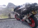
Top of stelvio pass96 viewsI know not in my disco. . but one hell of a road to travel on two or four wheels
|
|
transfer box leak - apparently not529 viewsleak discovered today crap
|
|

NOT Mine !!69 views
|
|

LP scoped 222 viewsBy connecting a Low Amps probe to the fuel pump's voltage supply wire, you can view the pump's current waveform on a digital storage oscilloscope (DSO). The scope pattern will reveal internal wear in the brushes and commutator that may not show up in a traditional pressure or volume test.
Observing the waveform will show if the pump's amp draw is normal for the application or is high or low, and if the pump is operating at normal speed or is running slow. Problems such as a bad spot on a commutator or a short or open in the armature also will be obvious in the waveform.
A "good" electric fuel pump waveform will generally seesaw back and forth with relative consistency and minimal variation between the highs and lows. A "bad" waveform will show large or irregular drops in the pattern, with large differences between the highs and lows.
|
|

Makita knot and nail 225 views
|
|

Makita knot and nail 120 views
|
|

On Holiday20 viewsIn the Lakes, Hardknott pass, by the fort
|
|
Wheel not touching the ground, Access height. jack not touched466 views
|
|
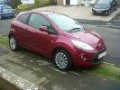
Girlfriends new Ford KA (ala Fiat 500 in another form!!) side view145 views
|
|
| 788 files on 2 page(s) |
 |
1 |  |
|