| Search results - "monitor" |

Reversing monitor view, wireless receiver behind gear lever92 views
|
|
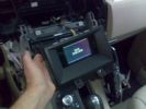
MONITOR SMONTATO112 views
|
|
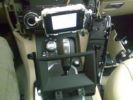
MONITOR STACCATO110 views
|
|
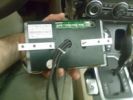
STAFFE POSTERIORI MONITOR99 views
|
|
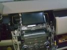
MONITOR INSTALLATO101 views
|
|
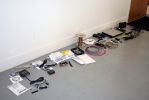
01313 viewsAll the new junk laid out on the floor.
Kenwood KOS-V1000 AV Controller
Kenwood KCA-iP500 iPod Control Interface
Kenwood KOS-L702 Monitor
Kenwood KCA-BT200 Bluetooth interface
Kenwood KNA-G510 Add-on navigation system
|
|
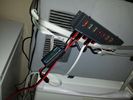
power monitor317 views
|
|
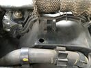
Monitoring hole.4 viewsHole for monitoring the timing belt.
|
|
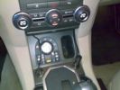
CORRENTE MONITOR E PC91 views
|
|
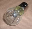
Land Rover Stop Tail Light dual filament bulb nominal 12 volt 21 / 5 watt filaments1427 viewsThis is the Land Rover part number 264590 dual filament bulb, (P21/5), that inserts into the upper two tail lamp receptacles. In the upper one, both filaments function, in the lower one, only the 5 watt tail light filament functions.
I regard it as not a good practice to routinely switch bulbs when the tail light filament, (5 watt), burns out on the lower bulb. The broken filament can jiggle over onto the brake light filament, (21 watt), and short the circuit to ground or something else not predicable.
There are also arguments to say that quality control is better on the Land Rover marketed bulbs than say far east sourced bulbs. Filament construction, and hence resistance can vary and mislead the current sensing circuits monitoring the signal light systems. Also when the bulbs are properly installed, all filaments should be standing vertically and not at any slope.
These are the sort of obscure circumstances that can lead to false trouble messages on the display, dropping to the stops, and subsequent concerns - all over a tail/signal light bulb.
For example, the filament life of both the tail light and the brake light filaments in the P21/5 bulb is significantly less than the USA common 1157 dual filament bulb, (1000/250 vs 5000/1200 hours); brightness in the P21/5 is a bit more, (3cp/35cp vs 3cp/32cp where cp is candle power), but current consumption is oddly less, (0.44a/1.86a vs 0.59a/2.10a where a is amps). It is the quest for efficiency vs maintenance trade off.
|
|
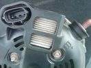
Alternator Plug and B+ terminal918 viewsPictured is the rear of the older Land Rover part # YLE500190 alternator showing the shiny cooling fin of the Regitar VRH2005-142 regulator under.
The first pin in the far left side of the connector is numbered #1 in the LR electrical wiring diagrams and is Battery Voltage Sensing (BVS); the middle pin, #2 receives a Pulse Width Modulated (PWM) signal from the Engine Control Module (ECM), and the right pin, #3 carries a PWM signal back to the ECM. Terminal Pin #2 on the LR wiring diagrams is called Alternator Control or ALT CON; Pin #3 per LR is called Alternator Monitoring or ALT MON.
Pin #1 is similar to what in older designs used to be called A or Batt, but is now called by Denso, S, AS, or Alternator Sensing for this design. Pin #1 also provides power to excite the alternator at startup until the PWM instructions over ride the battery voltage info. Land Rover calls the electronics under the pins a Smart Regulator, ironic, as it has to follow orders from the ECM rather than give the orders - new age thinking I guess. This is different from older design internal regulators that look at just the battery or the electrical buss voltage and then decides itself what to do.
It is almost like we are back to the external regulator designs of old, except that the ECM may decide that instead of telling the alternator to make more power, to load shed, and hence shut down the heated windscreen, seats, or whatever other electrical loads it decides are appropriate. My view is that the "smarts" are in the ECM and that the "regulator" should be regarded if not dumb, then as being a slave to the ECM.
|
|

monitor above chubby box - fold away behind the box85 views
|
|
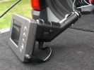
Monitor monted on 12v plug43 views
|
|
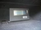
Genesis digital battery system - monitor in top glovebox323 views
|
|
264 views
|
|

Monitor per retrocamera48 viewsNavigatore aftermarket con schermo da 6"
|
|
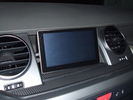
Aspetto sul cruscotto del monitor56 views
|
|

Additional 12V power, battery monitoring and USB sockets104 views
|
|
clearout fridge monitor0 views
|
|

Thread upload2 viewsImage uploaded in thread 200758
|
|
146 viewsbuilt painted and ready for monitor (NEXT BASE)
|
|

Car battery monitor19 views
|
|
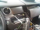
Monitor 8" LCD in fase di montaggio96 views
|
|
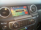
Monitor 8" LCD installato104 views
|
|

Monitor in viewing position39 views
|
|
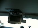
Distance view of monitor in viewing position54 views
|
|
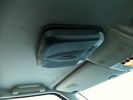
Monitor in stowed position53 views
|
|
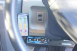
796 viewsIn cab view of battery management monitors
|
|

Newly installed Freelander2 headrest monitor10 views
|
|

NAS 7 Pin Round Socket + 4 Pin Flat Socket oriented as installed.752 viewsThis is the layout you see when you look into the NAS Land Rover sockets as installed at the rear of the LR3/4. The flat 4 pin socket is located under the round socket.
Wiring order is relative to the slot on the round socket, and hence the same as the other jpg where the slot is shown at the top.
The CJB monitors the front and rear turn signal lamps and can detect if more than four lamps are fitted, (the side turn signal lamps are not monitored). This is another reason for using genuine LR bulbs as off shore bulbs can have varied and out of spec resistance values.
When a trailer is detected, the trailer warning indicator in the instrument cluster is supposed to flash green in synchronization with the turn signal indicators.
If one or more of the turn signal lamps on the vehicle or the trailer are defective, the trailer warning indicator will cease to flash any longer. This is to alert the driver to probably bulb failure.
If the trailer has LED lamps installed, and no LED adapter circuitry is used, most likely the trailer will not be sensed and systems such as the backup sensors will not be disabled.
|
|
327 views
|
|

Monitor73 views
|
|
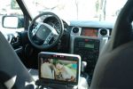
tv on back monitor + video on front115 views
|
|
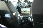
tv on back monitor 108 views
|
|
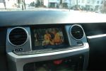
front playing video from ipod136 views
|
|
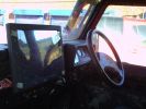
169 viewsthis is the 15\'\' touch screen monitor
|
|
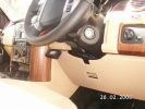
236 viewsVehicle Unit Display held on with Velcro, easily removable
|
|
Thread upload19 viewsImage uploaded in thread 174038
|
|
1337 views
|
|

Tyre pressure monitoring valve23 views
|
|

27 views
|
|
|
|
|
|
|