| Search results - "main" |

Main road to Isafjörður in the northwest fjords of Iceland112 views
|
|

Thread upload12 viewsImage uploaded in new thread
|
|

Chiave aperta12 viewsUna volta estratto il circuito stampato, facendo leva col cacciavite sulla parte rimasta attaccata ho prelevato la lama della chiave da inserire nel box nuovo.
Once you remove the printed circuit board, leveraging with the screwdriver on the part remained attached, I picked up the blade of the key to be inserted in the new box.
|
|

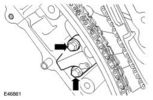
remains of tensioner bolt25 views
|
|

Thread upload1 viewsImage uploaded in new thread
|
|
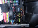
Permanent 12V supply271 viewsPhoto taken of TFC\'s D3 showing where you can take a permanent +12V supply, from the main fuse board behind the glove box.
|
|
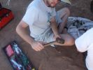
13 How to care for tools303 viewsWhat happened to the sledge hammer after 2 hours of beating my seized and cracked disk/park brake assembly to bits. Now down to 1 hammer remaining. At least by this time it was getting cooler (down to 40 deg C)
|
|
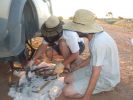
16 All the remains of a D3\'s parking brake373 viewsAfter 4 hours of hammering, finally removed the disk/park brake drum, and nearly all the parking brake bits fell to the ground. Cut rhe remaining brake cable loose as it was wrapped around the hub and a bit melted. Also having 2 jacks + 2 jack stands will support 4 hrs of hammering on the side of my D3.
|
|

Chassis harness to main harness116 viewsDescription: Chassis harness to main harness
Location: Below LH rear wheelarch
Part No.: YPC909640 Colour: LIGHT GREY Cavities: 18WY
Harness: CHASSIS HARNESS
|
|
61 views
|
|

Letting a D3 pass in the Goyt Valley66 viewsStopped to let a D3 and his van-in-distress pass on the main slope down to the reservoirs in the Goyt Valley
|
|
Waiting for a D1 to pass in the Goyt Valley67 viewsStopped to let a D1 and his vectra-in-distress pass on the main slope down to the reservoirs in the Goyt Valley
|
|
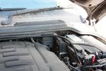
111 viewsBattery to battery cable in main battery box
|
|
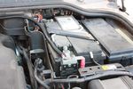
113 viewsBattery to battery cable attached to main battery
|
|

28 viewspdc main plug?
|
|
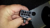
Connector from Main Loom to Heated Rear Seat Harness20 views
|
|

Thread upload9 viewsImage uploaded in thread 189350
|
|
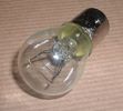
Land Rover Stop Tail Light dual filament bulb nominal 12 volt 21 / 5 watt filaments1427 viewsThis is the Land Rover part number 264590 dual filament bulb, (P21/5), that inserts into the upper two tail lamp receptacles. In the upper one, both filaments function, in the lower one, only the 5 watt tail light filament functions.
I regard it as not a good practice to routinely switch bulbs when the tail light filament, (5 watt), burns out on the lower bulb. The broken filament can jiggle over onto the brake light filament, (21 watt), and short the circuit to ground or something else not predicable.
There are also arguments to say that quality control is better on the Land Rover marketed bulbs than say far east sourced bulbs. Filament construction, and hence resistance can vary and mislead the current sensing circuits monitoring the signal light systems. Also when the bulbs are properly installed, all filaments should be standing vertically and not at any slope.
These are the sort of obscure circumstances that can lead to false trouble messages on the display, dropping to the stops, and subsequent concerns - all over a tail/signal light bulb.
For example, the filament life of both the tail light and the brake light filaments in the P21/5 bulb is significantly less than the USA common 1157 dual filament bulb, (1000/250 vs 5000/1200 hours); brightness in the P21/5 is a bit more, (3cp/35cp vs 3cp/32cp where cp is candle power), but current consumption is oddly less, (0.44a/1.86a vs 0.59a/2.10a where a is amps). It is the quest for efficiency vs maintenance trade off.
|
|
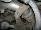
Charge Air Pipe - turbo end.101 viewsThe maint manual identifies releasing the pipe hose clip in the center of the photo. Pity who ever built this engine Put the hose in such a position that access to it was near impossible. I released the other clip at the turbo end of the flexi hose. Easy to get to but a right git to release the hose of the turbo.
|
|

Thread upload9 viewsImage uploaded in thread 189350
|
|

2 Maintenance Schedules - Gasoline Engines17 views2 Maintenance Schedules - Gasoline Engines
|
|

3 Maintenance Schedules - Diesel Engines12 views3 Maintenance Schedules - Diesel Engines
|
|
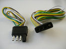
4 pin NAS flat connector from NAS small trailer382 viewsThe connector with the three exposed pins is the end that would commonly be located at the trailer hitch end, (front), of a small NAS lightweight trailer that has no electric brakes. This plug would connect into the flat 4 pin connector at the rear of the 3.
Note the order of the pin functions and wire colours: White is ground; the next pin is for tail/marker lights using the Brown wire; the Yellow conductor is for the left turn signal, and the far pin uses the Green conductor for the right turn signal.
There is no separate brake light conductor as NAS spec vehicles most often combine the brake and signal light functions to the same bulb filament rather separate filaments in different bulbs. The LR factory harness resolves that design difference.
Fortunately, the Land Rover NAS assembly pin order for the 4 pin flat plug maintains the above described conventions.
|
|

C2243R80 viewsDescription: Main harness to engine compartment harness Location: Behind passenger compartment fusebox
|
|

24 views
|
|

Thread upload36 viewsImage uploaded in thread 92518
|
|
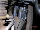
60 viewsOne bolt is visible at the front, but the other two are down the left hand side and best accessed by removing the small plastic guard behind the bumper. I also removed the small metal radiator guard between the bumper and the main sump guard (but that was mostly to retrieve the spanner I dropped!). The only issue with removing the plastic guard is the stupid plastic clips that hold it on may need to be replaced.
|
|
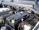
BCI Group 40R Deka 640RMF battery showing vent hose run forward to windshield washer reservoir area 1430 viewsRecessed post "Euro profile" battery to "match" OEM and stock Land Rover bracket; note that the Traxide SC80-LR module is mounted at an angle to allow for the main cable to sit under the cover so cover still closes.
The battery is a nominal 7", (180mm), high, but sits on a 1" battery spacer set under to raise the bottom front end of the battery such that the approx 11", (290 mm), length of the BCI 40R battery rises above the angled plastic nibs at the forward end bottom of the case front; hence sufficient space, (1/4", 5mm) remains at the brake reservoir end.
Also the 40R battery does not have hold down "flanges" on each end; on the sides yes, but not the ends so no additional length is required.
When I had to replace the 40R, this time I installed the shorter, (9.625"), taller, (7.5") Interstate BCI 47 / DIN H5 battery which eliminated the spacer on the bottom and better fit the stock LR tie down bolt lengths. Deka also has a BCI 47 / DIN H5 that would work fine as well.
|
|

Thread upload13 viewsImage uploaded in thread 138228
|
|
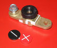
Battery Disconnect side post with + & - caps, top view617 viewsThis disconnect is designed for side post batteries. It can be used on either the + or - terminals. It can also be installed at the "other" end of the battery cable as well. In my install of the Aux battery, I installed this on the negative ground cable where the cable attaches to the body sheet metal. I have never used it but it seemed like a good idea at the time. The main battery hookup is pure stock.
For the hot side of the Aux battery, an Anderson PowerPole was used inline for the cable between the Aux and connecting to the spare bolt hole at the + post of the Main battery cable.
|
|
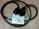
Box Closed with 7 Blade NAS connectors586 viewsBox closed up and ready for use. The box and cable connectors are reasonably weather tight and hence can be submerged for a bit while doing a creek crossing but as with the 3, do not use the creek bed as a parking stall. Similarly, the connector recessed into the bumper will probably remain somewhat dry as long as you keep moving but if you get stopped, well that is another story.
As such, I put a vial of desiccant in the metal box prior to closing it up to reduce corrosion due to moisture build up.
|
|

Brake Light Switch, Find, Remove, and Install Instructions 7853 viewsThis is a two page doc outlining where to find the brake light switch, how to remove it, and then install the new one.
Note, do not move the brake pedal when removing or installing the switch. Let the brake pedal hang where it wants to. The switch design is actually cunning, and as such is supposed to make the removal and install fool proof. Hence if you think too much about it, you can wreck the new switch.
If you want to inspect the interior of the switch, wait until you have removed the old switch. You can then just unsnap the blue from the white to get it apart. Inside, the switch is quite simple, (no circuit boards), but it will probably show black dust from failing contacts.
I think the reason the switch fails is that the Normally Open, (NO), contacts of the brake light contacts were made too light to carry the current load for make and break of the tail light filaments. I also think the black dust created then fouls the Normally Closed, (NC), second set of contacts for the ABS circuit. As such, the Normally Closed contacts become intermittent in operation and display as a fluctuating open and closed circuit condition to the ABS system when the ABS should be seeing a steady closed circuit. Hopefully the replacement switch contacts are more robust and may be as I recently replaced my switch again just as a matter of maintenance. While in a redesign, ideally the NC contacts should be sealed or at least separated from the NO contacts, when I inspected the removed switch, this time there was no black dust present.
Probably the removed switch will have a Land Rover oval logo moulded into it, the new one, FOMOCO.
|
|

Thread upload0 viewsImage uploaded in thread 183644
|
|
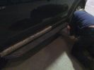
D3 Side Step Repairs150 viewsI then punched out the remaining rivets from the step edge. I used a small hammer and a small punch.
|
|
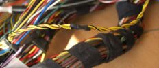
Can Pair After73 viewsThe can pair repaired with twist maintained
|
|
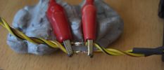
Can Pair Repair84 viewsThis is the high speed CAN bus Pair. By over twisting and keeping the repair short i will maintain the very important twist. Good soldering is a must it looks ropey in this shot but it is not, note the heat shrink pre placed on the wires to the right.
|
|

Central Door Locking Operation Description1458 viewsThis 17 page pdf explains how the door locks are supposed to operate. Note that on page 9/17, the explanation of the operation of the hood ajar switch is wrong. It operates similar to the door and tailgate ajar switches; that is when a "door" is closed, the switch is closed to maintain a ground back to the CJB. Opening the hood, door, or tailgate removes the ground breaking the circuit and hence allows for an alarm condition.
|
|
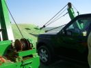
All at sea in an LR3105 viewsThe ferry from the mainland to Mazira Island was packed to the gunnels with vehicles. My LR3 was last on and they left the bow doors partially open for 14 lonnnnng sea miles across the Arabian Gulf!
|
|

Campsite on Mazirah208 viewsA fabulous deserted sandy beach that runs for miles on the east coast of Mazirah Island, off the Omani mainland , views across the Arabian Gulf, and turtles and hatched terrapins.
|
|
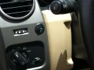
Long Ranger auxilairy fuel tank pump switch and tank gauge308 viewsFitted to the right of the air vent thumbwheel, the neat combination switch and gauge take sup no room at all. Switch locks on or off, but no pump running warning lamp! Contents of the tank are indicated by 5 LEDS, 4 green and 1 red for full, 3/4, 1/2, 1/4 and empty. Pump transfer rate of just 2 litres p/min is disappointing. I transfer on the move when main tank is at 1/4.
|
|

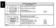
Main Bearing Journal Clearance10 views
|
|

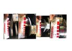
84 views
|
|

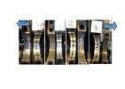
76 views
|
|

Main Navigation Menu showing 4x4 info and timed Climate173 views
|
|
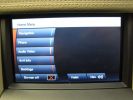
Main Navigation Menu showing 4x4 info 143 views
|
|

Maintenance Check Sheet Arduous 3.0 TDV6 Models to 11MY Discovery 4 / LR424 viewsMaintenance Check Sheet Arduous 3.0 TDV6 Models to 11MY Discovery 4 / LR4
|
|

Maintenance Check Sheet Rest of World 3.0 TDV6 Models to 11MY Discovery 4 / LR418 viewsMaintenance Check Sheet Rest of World 3.0 TDV6 Models to 11MY Discovery 4 / LR4
|
|

Maintenance Check Sheet All Models UK & EU to 11MY Discovery 4 / LR412 viewsMaintenance Check Sheet All Models UK & EU to 11MY Discovery 4 / LR4
|
|

Maintenance Check Sheet All Models UK & EU Discovery 415 viewsMaintenance Check Sheet All Models UK & EU Discovery 4
|
|
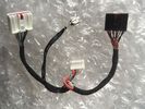
Thread upload9 viewsImage uploaded in new thread
|
|
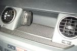
Mitac Mio Cradle448 viewsMitac Cradle adapted to fit to L shaped bracket (remainder sits under rubber mat) Allows PDA to be quickly removed when leaving the car unattended.
|
|

Main Picture45 views1 Pic
|
|
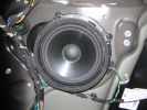
main speaker405 views
|
|
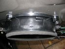
main speaker adapter plate360 views
|
|
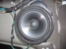
main speaker 2361 views
|
|

Main secondary gear repair bush492 viewsPDF file of engineering drawing of bush turned up to repair the main secondary gear in the EPB gearbox.
Old gear has to be drilled out accurately to the external diameter of the bushing shaft.
|
|

D3 Maintenance Schedule - Kilometre version130 views
|
|

170 views
|
|

Italian Maintenance Check Sheet251 viewsLRE008ITA (2)
DISCOVERY 3 SCHEDA DI CONTROLLO MANUTENZIONE (TUTTI I MODELLI INGHILTERRA & EUROPA)
|
|

Italian Maintenance Check Sheet228 viewsLRE011ITA (2)
DISCOVERY 3 SCHEDA DI CONTROLLO MANUTENZIONE (TUTTI I MODELLI PER CONDIZIONI GRAVOSE)
|
|

Italian Maintenance Check Sheet138 viewsJLR 11 81 14_7E (7)
DISCOVERY 3 SCHEDA DI CONTROLLO MANUTENZIONE (TUTTI I MODELLI RESTO DEL MONDO)
|
|

service183 views
|
|

Disco3 Maintenance Checklist26 views
|
|

Thread upload28 viewsImage uploaded in thread 132681
|
|
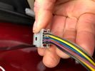
Thread upload14 viewsImage uploaded in thread 177861
|
|
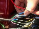
Thread upload12 viewsImage uploaded in thread 177861
|
|

Maintenance check list281 views
|
|
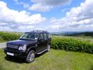
Disco 4 in mid Wales306 viewsDisco 4 (MY11) in Bournville. Taken in the sun as otherwise it mainly looks black!
|
|
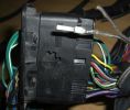
New Speaker Cables.111 viewsThis is the door connector, Main loom to Right, Door side to the left. to the top of the connectors you can see green and Green white wires which are the speaker ones. The door wiring is premium and has two pairs, the main loom was a 1 pair high line, so i am adding the pair you see (one already pinned up) to upgrade the loom to premium.
|
|

Some of the damage remaining from Hurricane Gonu - this was caused by flash flooding in the wadi86 views
|
|
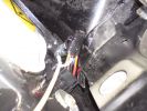
Again just another pic of the wiring into the main175 views
|
|
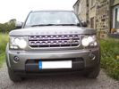
HID Dip, Halogen main50 views
|
|

CALENDAR ENTRY - Christmas Eve at Calke Abbey497 viewsSlightly photoshopped to remove the colour in the background. Have the original if you prefer!
|
|

Remains of a troop carrier next to the road. On the way to Ondjiva. Worst road in the world!162 views
|
|
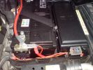
Main battery and accessory fuse box216 views
|
|
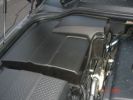
Main Battery Cover170 views
|
|
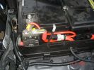
Aux to Main Battery201 views
|
|

disco at finore76 viewsfound a little patch that strayed from the main road near finore, co clare.
|
|
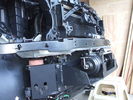
Front-right view (looking forward) of partially installed winch and mount124 viewsThe closest bracket, with three rubber grommets, is the air bag sensor. Before beginning any of this work, be sure to disconnect battery and discharge any remaining electrical power. I didn't want to accidently drop this assembly and cause the airbags to deploy.
|
|
100 views
|
|

LR4 2012 MY Maintenance Schedule18 viewsLR4 2012 MY Maintenance Schedule
|
|

Remainers Cry Babies21 views
|
|

Fluid, Filter/Pan Combo removal and install5980 viewsThese are the LR instructions re removal and install of the plastic pan/filter combo for the ZF 6HP26X transmission on the 4.4L petrol V8 LR3.
The instructions tend to ignore the reason you have to lift the right hand side of the engine about 40 mm. This is because of a frame cross member that interferes with dropping down of the plastic pan. The real problem is a vertical "oil filter spout" that rises out of the filter/pan combo up into the transmission. The spout is the suction pipe for filtered transmission oil back up into the tranny.
On the metal pan versions, the filter is separate from the pan, hence the filter remains with the tranny when the metal pan is dropped. The filter is then removed or installed independent of the metal pan, hence with the metal pan, there is no need to lift the engine.
If one is removing the plastic pan so as to install the metal pan, then some do not lift the engine but just drop the plastic pan enough to gain access to saw off the vertical plastic spout - it is a one time procedure.
Be aware however that the metal pan uses a flat gasket and the plastic pan uses a O ring like perimeter gasket that sits in a half round groove in the tranny casing. Also the metal pan uses 21 shorter torx M6x22.5 metric cap screws for the perimeter bolts. The plastic pan uses longer M6x28.5 torx metric cap screws.
|
|

15 views
|
|
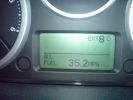
35.2MPG - after a 10 mile drive on back and main roads210 views
|
|

High Beams Main Beams Wiring Diagram76 viewsThis is the wire colors and connections for Dipped, Main, and Side Marker lights
|
|

Main Beam - Xenons (non adaptive)103 views
|
|

Back of main beam25 views
|
|

Main Liner with Rear Plus6 views
|
|

Spots + main beam110 views
|
|

Night All On Spots + Main beam136 views
|
|

No Spots Main Beam only110 views
|
|

secret shrine21 viewslocated in a secret place tgis old shrine is all that remains of an old buddist temple
|
|

Over the sands97 viewsInitially tried the car with all up weight - full auxiliary (115L)and main (85L) fuel tanks, dual spare wheels, and roof rack. Car had a marked tendency to tail end slide when on side slopes, especially in soft - really soft sand.
|
|

Two 109\'s on the main road between Dubai and Sharjah64 views
|
|

Two 109\'s on the main road between Dubai and Sharjah63 views
|
|

Nexus 7 main screen7 views
|
|

FBH Main Modules27 views
|
|
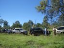
Rest stop after our first hill descent.191 viewsMode: TR Rock Crawl with HDC turned off as I found that the ABS kicked in too much. As we were in convoy I maintained a safe distance from car in front and just "feathered the brakes" as suggested by an instructor.
|
|
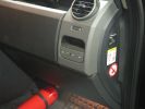
463 viewsFirst step in the journey, installed USB ports.
At the time I installed these, the goal was to use them in combination with the car-computer that resided in the back.
In the meanwhile, I dismantled the car-computer and nearly everything that was connected to it (touchscreen front, Wifi, DVB-T ...).
I kept the USB outlets in the front and turned them into charger for the appliances missus brings with her when we're on holiday. Mainly her iPod and smartphone ...
|
|

H7 Upgrade ABD vs philips standard main beam only HIDS4U85 views
|
|

Placement of mains plug39 views
|
|

Mains plug glued in place29 views
|
|

Placement of mains plug26 views
|
|

Discovery 4 DRL 117 viewsThe photo shows the Land Rover Discovery 4 fitted with the Land Rover Daytime Running Lights. These were fitted by Land Rover when I got the car. The are on when the lights are not. As soon as the main lights come on the DRL's switch off.
|
|
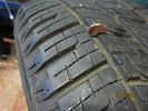
Almost 'full as new' tread remaining across all tyres24 views
|
|

Partial remains of battery terminal bolt - Oops20 views
|
|
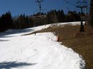
Main run in Kelchsau134 views
|
|

Engine 21 viewsThe remains of my 3.0ltr
|
|

11 January 2009 - 3107 viewsLevel of ice remaining on tracks
|
|
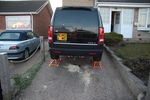
D3_ Maintenance21 views
|
|

Interstate Battery Dimension sheet641 viewsThis sheet is hard to find - the sheet is not on the Interstate corporate web site but some dealer web sites display it. The pdf shows most of their available batteries including the H7 and H8 sizes that are the LR North America replacement batteries for the main starting battery. These batteries are of the Land Rover desired "shallow" cycle high discharge current Maintenance Free, (Ca Ca), internal construction, (not AGM, but instead, Wet Flooded Lead Acid with battery "caps" and Ca grid separators).
For the AUX battery , the H6, (BCI Group 48), is probably similar in dimensions to the Varta E12V75N that is popular in Australia. For that battery to fit in the second battery compartment, you must grind out the angled nibs on the inside front bottom of the LR black plastic surround, something I did wish to do and hence installed a Group 40R on a spacer. Alternately, one can choose an Interstate BCI Group 47 which is similar to a DIN H5 for the AUX location. I did this when I had to replace my 40R. No vertical spacer is required and the stock battery tie down bolts and clamp work well.
|
|

Discovery 3 Maintenance Check Sheet (All Models Rest of World) - miles182 viewsDiscovery 3 Maintenance Check Sheet (All Models Rest of World) - miles
JLR 11 81 10_7E
|
|

Discovery 3 Maintenance Check Sheet (All Models UK & EU) - miles214 viewsDiscovery 3 Maintenance Check Sheet (All Models UK & EU) - miles
JLR 11 82 10_6E
|
|

Discovery 3 Maintenance Check Sheet (All Models Arduous) - miles154 viewsDiscovery 3 Maintenance Check Sheet (All Models Arduous) - miles
JLR 12 05 10_6E
|
|

126 views
|
|

L319_Discovery_4_MY2010-2011EU_Maintenance_Check_Sheet_-_all_Models_-_km34 views L319_Discovery_4_MY2010-2011EU_Maintenance_Check_Sheet_-_all_Models_-_km
|
|
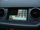
Main screen, currently searching1253 views
|
|
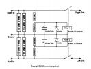
LED tamer circuit1007 viewsThis circuit is and will remain my property unauthorized commercial exploitation is forbidden.
|
|
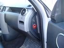
Air Suspension ECU Fuse 35P Shut Off Switch2635 viewsA more distant view of the shut off rocker switch in the ON position which is the normal position for when all is working as Land Rover intended.
Ideally, (but not totally necessary), the F35P circuit should be powered or de-energized after the various computers have gone to "sleep".
Similarly, removal of the F26E or F3E fuses is preferable after the computers have all gone to sleep but it appears that no real damage will be done if the fuses are removed while the system is energized. Pulling F26E is the main full time fuse that powers the air suspension computer. As such, once F26E is removed, pulling F3E is not really required.
Power for the compressor goes thru the 60 amp fusible link and relay, however control of the relay is via the air suspension computer so depowering the air suspension computer effectively depowers the air compressor and the internal exhaust valve relay/port.
|
|

Battery Maintainer pigtail sticking out of Grill728 viewsThis is all you see when everything is put back together - just the pigtail and Weather Pack blanking plug. Most often, I have it all tucked back behind the grill.
In winter, there may be a second cord hanging out as well - the 120 VAC power cord for the engine block heater, a tea kettle like element inserted in the engine block. NAS petrol V8's do not have the Fuel Burning Heater, (FBH), installed, but instead in cold area markets have the block heater element assembly available as a dealer installed option. There is an argument to say that the heating element is factory installed in all cold climate V8 gasoline engines, however the appropriate power cord is not. If true, this means that all one needs to purchase is the area specific power cord and plugging in / attachment to the engine block located block heater.
As such, you will often see a conventional 120VAC three prong power plug hanging loose out of the grill of most vehicles here in the wintertime. In summer, most drivers tuck the plug back behind the grill as it is no beauty mark.
|
|
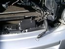
Battery Maintainer switch box and connector 723 viewsThe Hammond box contains a DPDT toggle switch with centre off. The Positive and Negative from each battery feeds to the switch. Depending on the setting of the toggle, (full left, full right,or centre off),the respective batteries connect into the pigtail that can stick out thru the grill when one wishes to connect the charger.
This allows one to charge each battery independently via a suitable battery maintainer. I use a CTEK unit that feeds a maximum of 3.3 amps at 14.4 or 14.7 VDC, depending upon setting. The wiring therefore allows for a slow recharge of either of the batteries separately if either one requires such.
|
|
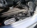
Battery Maintainer switching box plug and CTEK Multi US 3300 charger. 706 viewsThe CTEK Multi US 3300 maintainer is just sitting there for the picture. In addition to topping up both batteries, the CTEK can provide power such that if the batteries were completely dead, there would be power to the door locks and hence, one could most likely still gain access via the remote once the starting battery charged up a bit.
The Land Rover recommended method is via the hidden key hole which is mechanical, however that presumes the mechanism is not frozen from lack of use. As such, the manual lock should be exercised at least once a year to ensure that it still functions.
The blanking plug sitting on top of the plastic box is of the GM Weather Pack series. That is what I like to use for vehicle wiring that is subject to moisture, (or not).
|
|
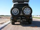
kaymay rear bumper/tire carrier493 viewsthis is on delivery to me.... ;) . it went on easily but i will have it modified to place right wheel more toward middle like disco II. i will only ever use the laft side for jerry can or something, not another tire. i don't like how right tire totally blocks main lamp.
|
|
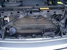
Plastic cover and Box back on in Front of Radiator 637 viewsThe wiring loom is below the cover - nothing is crushed or distorted and all fits back together OK. The black plastic box with the DPDT, (centre OFF), toggle switch is to tie the battery maintainer to each of the two batteries per the Traxide Dual battery install. I can also get power to the power door locks if all fails.
|
|
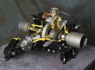
Rear Differential cutaway with E-Locker 1210 viewsThis jpg is from the link below.
There are another ten or so cutaways plus a whole file group showing a 2005 LR3 sectioned for the 2005 Chicago Auto show. Each jpg has an enlarge function to the bottom right of a main picture.
On one jpg you can see right into the stepper motor.
http://www.cutawaycreations.com/cutaways.php?project=land-rover-electronic-rear-differential#/IMAGES/car4/images/image1.jpg
Both the front and rear differentials are manufactured by Dana Spicer in the UK. Dana calls them a Clamshell design.
|
|

Smooth off road ride!399 viewsThis was the first time I took my LR3 off-road. I traded my Jeep Wrangler for this vehicle so I was used to heading into the rugged mountains. I was very amazed (as were my friends in their Jeeps) just how level the LR3 remained as I navigated over various dips and mounds. You can see the Cherokee behind me couldn't say the same.
|
|

D4 non-3L arduous maintenance checklist29 views
|
|

Maintenance Check Sheet Non 3.0 TDV6 Models To 11MY Arduous Discovery 4 / LR412 viewsMaintenance Check Sheet Non 3.0 TDV6 Models To 11MY Arduous Discovery 4 / LR4
|
|

Maintenance Check Sheet Non 3.0 TDV6 Models To 11MY Rest Of World Discovery 4 / LR417 viewsMaintenance Check Sheet Non 3.0 TDV6 Models To 11MY Rest Of World Discovery 4 / LR4
|
|

D4 non-3L maintenance checklist (rest of world)29 views
|
|

Thread upload6 viewsImage uploaded in thread 155707
|
|

Maintenance Check Sheet66 viewsMaintenance Check Sheet
|
|

Maintanance Disco 357 views
|
|

LTB00004 - Technical Bulletin - Crankshaft Main Bearing Carrier Leak - Repair Procedure65 views
|
|
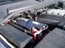
Main starting battery showing 1/2" hole drilled for power cable egress910 viewsView of OEM battery in Left Hand Drive LR3. This is supposed to be a Battery Group BCI 49 or H8 sized battery but in reality is the slightly shorter BCI 94R or H7 battery that fits easier lengthwise, (12 3/8" vs 14").
Note the 10mm hole drilled in plastic of surround to allow for entry of main power cable that runs between batteries. The cable bolts to a spare 6mm threaded hole in the OEM battery cable end; the light gauge wire runs to the front of vehicle to a connector for the CTEK MULTI US 3300 charger. Coloured felts, (red and green), are a material treated to reduce battery post corrosion. The OEM battery ground cable is only about a foot long and runs to an 8mm stud located on the inner fender just to the rear of the fuse case.
|
|
Main Battery showing aux cable feed running off positive battery post.776 viewsThe black wiring loom around the battery cable to the aux battery was a part provided with the Traxide kit. My goal was to run the cable low enough such that the battery box cover would go back on as previous.
Note the hole drilled in the side of the battery box such that the new cable could thread thru to allow the battery box top to still fit the same as prior to the addition of the cable to the auxiliary battery.
|
|

Thread upload14 viewsImage uploaded in thread 162047
|
|

Thread upload13 viewsImage uploaded in thread 162047
|
|

Thread upload1 viewsImage uploaded in thread 183482
|
|

Thread upload7 viewsImage uploaded in thread 166942
|
|

Thread upload7 viewsImage uploaded in thread 146481
|
|

131 views
|
|

38 views
|
|

1973 Triumph TR617 views
|
|

Thread upload13 viewsImage uploaded in thread 163793
|
|

Thread upload0 viewsImage uploaded in new thread
|
|

Thread upload1 viewsImage uploaded in thread 197728
|
|

126 views
|
|
Thread upload14 viewsImage uploaded in thread 74474
|
|
Thread upload20 viewsImage uploaded in new thread
|
|

30 views
|
|

Maintenance Fluid Specifications for Legacy LR Vehicles175 viewsMaintenance Fluid Specifications for Legacy LR Vehicles1
|
|

Thread upload5 viewsImage uploaded in thread 157943
|
|

Thread upload5 viewsImage uploaded in thread 157943
|
|

Thread upload6 viewsImage uploaded in thread 157943
|
|

Thread upload7 viewsImage uploaded in thread 157943
|
|

Thread upload7 viewsImage uploaded in thread 157943
|
|

Thread upload7 viewsImage uploaded in thread 157943
|
|

LR3 maint schedule - original13 viewsSchedule is at launch in mid 2000s. May have been revised since. This is the LR shop scheulde.
|
|

121 views
|
|

Thread upload1 viewsImage uploaded in new thread
|
|

Thread upload10 viewsImage uploaded in thread 171634
|
|
Thread upload54 viewsImage uploaded in thread 52879
|
|
Thread upload6 viewsImage uploaded in thread 147295
|
|
Thread upload6 viewsImage uploaded in thread 189350
|
|
Thread upload8 viewsImage uploaded in thread 189350
|
|
Thread upload10 viewsImage uploaded in thread 128829
|
|
Thread upload20 viewsImage uploaded in thread 157551
|
|
Thread upload1 viewsImage uploaded in new thread
|
|

Thread upload1 viewsImage uploaded in new thread
|
|
6 views
|
|
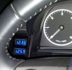
Battery meters26 viewsBattery meters - top for Main and bottom for Optima Yellow-top
|
|
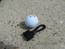
MOST fiber optic loop tool469 viewsThe looping tool in the jpg uses the Land Rover type plastic fiber optic cable with both ends feeding back into a female fiber optic connector that mates with the male fiber optic connectors on the Land Rover system.
The purpose of the loop is to allow one to disconnect MOST connected items such the BlueTooth module or the HK amplifier but allow the MOST system to still transmit signal from the head unit as the circuit would remain closed and hence complete. Of course with the Bluetooth module disconnected, there would be no Bluetooth available, however the radio and NAV would still function.
The looping tool allows one to troubleshoot the system by removing one component at at time from the MOST loop. In other words, what might appear to be a radio problem could be a Bluetooth problem - that sort of thing.
|
|
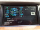
chinese satnav36 viewsthis screen shows sts (very useful....not) and speed which used to be on main display but after upgrade is not
|
|

Thread upload9 viewsImage uploaded in new thread
|
|

Maintenance Check Sheet214 views
|
|
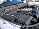
Overview of engine compartment from Main Battery side, (Passenger, LHD), looking across to Aux Battery753 viewsNote labels on main battery cover. The one you cannot read says that an auxiliary battery is installed on the other side. This is to warn service people should they wish to shut off all battery power.
The main starting battery is supposed to be of CaCa separator construction and DIN H8 or BCI Group 49 size. This means Calcium separators Wet Flooded Lead Acid, 13.9" long, 7.5" high and 6.9" wide.
On the Aux battery cover is a label saying to disconnect the blue Anderson single pole connector located under the cover by the brake reservoir. BCI Group 40R battery is small enough that the cover goes back on.
|
|
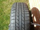
discovery s alloys23 viewstyre wear and tread remaining
|
|
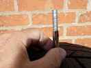
discovery s alloys14 viewsremaining tread depth
|
|

Yamba - Main Beach94 views
|
|
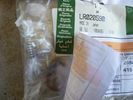
LR020590 KIT - COMPRESSOR 1481 viewsThere are 4 main parts you can get besides a whole compressor. This is the one with only a spring, o-ring and rubber valve.
YWB500220 electrical, fuse & relay, relay ENGINE COMPARTMENT, 70 amp 1
LR020590 KIT - COMPRESSOR 1
JPO500010 KIT - COMPRESSOR 1
VUB504700 - Dehydrator PARTS
|
|
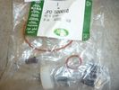
JPO500010 KIT - COMPRESSOR 1437 viewsThere are 4 main parts you can get besides a whole compressor. This is the one with more bits.
YWB500220 electrical, fuse & relay, relay ENGINE COMPARTMENT, 70 amp 1
LR020590 KIT - COMPRESSOR 1
JPO500010 KIT - COMPRESSOR 1
VUB504700 - Dehydrator PARTS
|
|

Unknown bird at sand pumping station near mouth of the Tweed River124 viewsNoisy little bugger who remained under walkway but eventually came out and then flew away flying low over water towards Tweed Heads.
|
|
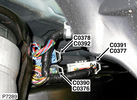
C0390 Chassis harness to main harness228 viewsPart No.: YPC909600
Colour: BLACK
Cavities: 18WY
Harness: CHASSIS HARNESS
Location: Below LH rear wheelarch
|
|

4x4 info Android1 views4x4 info provided by Android unit AC8667L
https://es.aliexpress.com/item/1005003703556182.html?spm=a2g0o.order_list.order_list_main.16.5949194ddA7E9L&gatewayAdapt=glo2esp
|
|

May the force of gravity remain with you......70 views
|
|
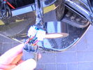
i took power for camera and the reversing signal from the main loom with scotch locked365 viewstape them up otherwise they will corrode. this area gets wet and dirty
|
|
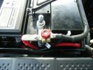
352 viewsThis is how the battery isolator is connected with the main battery.
|
|
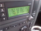
Voltage Display Page Radio Head Unit 118 14.2840 viewsThis shows the voltage/temperature/timer display page within the 6CD-465 radio head. There is a second file within this album, a doc file, that outlines the procedure to access the diagnostics.
The 14.1 volts number was the approximate vehicle system voltage with the engine running; the 118 number infers 11.8 volts which is the low power infotainment system shutdown cutoff voltage. The factory default setting is 135 or about 13.5 volts. By holding the keypad 1 button down, the 3 digit volts numbers will decrease 001 at a time until the keypad 1 button is released. Decreasing the number from 135 to some lower number should increase the time the system will remain on with the engine off.
The TEMP numbers refer to Fuel Burning Heater, (FBH), temperature values. 85 is apparently a high limit and 46 was the number when the jpg was taken. This number varies and given that there is no diesel fueled FBH in our NAS petrol engine vehicles, what the value refers to is unclear. The TIMER numbers also relate to the diesel fuel burning engine heater and perhaps make more sense being 00.
|
|
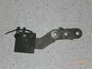
Radio Noise Suppression Capacitor NNW502820699 viewsThis is the radio noise suppression capacitor, part number LR020488 (previous NNW502820), that is mounted underneath and near the transmission. It is powered by fuse 10 amp F30E in the engine compartment. If F30E blows, (the fuse that also powers the transmission ECU), the problem is probably caused by the failed capacitor, not the ECU. A quick fix is just to disconnect the capacitor and replace the fuse as nothing bad seems to immediately result.
The above radio noise capacitor is not to be confused with LR004160, the ignition noise capacitor which is located under the black plastic engine cover on the right hand side above the air intake towards the rear of the engine.
The ignition capacitor is held on with a single 8mm bolt and a three wire electrical connector. Replacing the ignition capacitor as a routine maintenance prevention action at 100,000 miles, 160,000 km), has merit. It is a do it yourself kind of thing and easier to get at than the radio capacitor underneath.
|
|

Thread upload18 viewsImage uploaded in thread 121178
|
|

Transpo Regulator IN6349 Pin Assignment716 viewsThis pdf shows the Land Rover and Ford pin naming for the 3 pins in the receptacle of the Transpo IN6349 regulator that accepts PWM signals. This jpg is as if you are looking into the receptacle located on the alternator.
Also provided are the Transpo pin names that are in common use and that some may be more familiar with plus some comments re testing.
The IN6349 regulator is used in the newer LR part # YLE500390 alternator. For the older YLE500190 alternator, the regulator is a Regitar VRH2005-142 unit that is shaped a bit different than the newer IN6349 regulator. Externally, the main difference is that no shiny fins are visible on the rear of the newer YLE500390 alternator. The pin naming and numbering is the same for both and both alternators are interchangeable.
|
|

Thread upload5 viewsImage uploaded in thread 141729
|
|

Thread upload3 viewsImage uploaded in thread 174456
|
|

Thread upload2 viewsImage uploaded in thread 195246
|
|

Thread upload2 viewsImage uploaded in thread 195246
|
|

2009 - Rig Road - The main storm front87 viewsVisibility dropped to less than 100 metres.
|
|
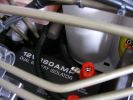
12v Isolator876 viewsEnsures that aux ery won\'t charge until the main batt is topped up and won\'t drain the main batt. I used the biggest I could find to take the load with no stress - especially the higher voltage on the landy. Came as a compete kit and works well.
|
|
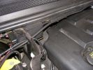
Main Feed799 viewsHere\'s the shielded positive feed from the main battery. Runs accross the fireall with lockties to support.
|
|

Frozen Satnav51 viewsThe left hand screen continues to update, as does the text in the detail view, but the map in the detail view is frozen at the first of the series of junctions - location circled in the main view
|
|

Italian Maintenance Check Sheet135 viewsJLR 11 82 14_6E (6)
SCHEDA DI MANUTENZIONE (TUTTI I MODELLI REGNO UNITO ED EUROPA)
|
|

Italian Maintenance Check Sheet145 viewsJLR 12 05 14_6E (6)
SCHEDA DI MANUTENZIONE
|
|

Thread upload2 viewsImage uploaded in thread 140528
|
|
Thread upload6 viewsImage uploaded in new thread
|
|

Taking letters off124 viewsUse Garden twine doesn\'t damage the paint, the remaining 3M tape can be removed easily without any chemicals, just scrape it off with your finger nails, a little polish and you can\'t tell anything was ever there.
|
|

Thread upload0 viewsImage uploaded in thread 186251
|
|

Vehicle Maintenance Log for LR3/4 D3/4 or other1135 viewsThis is a Excel file that you can download and then modify to suit. It is very simple, but allows me to keep track of most maintenance and fixes etc on my LR3. All columns and rows and boxes can be edited.
I did not erase any data in the various boxes so you could see how I am using it - again not very fancy but it works for me. Under the brakes column, one will see f6 r5 which is how I keep track of the condition of the brake pads. The dealer records the pad thickness at each oil change so that is where the numbers come from.
f is for Front Pads, 6 is for 6mm; r is for Rear pads, 5 is for 5 mm. New pads are about 10 mm; replacement is at 3 mm or less. The amber coloured brake wear dash warning light should come on at about 2 mm.
|
|

2009 - WAA Corner - Sand Storm Building97 viewsEarly on the day, a couple of hours before the main storm front arrived.
|
|

Wadi Bani Auf, Oman160 viewsLoose river-borne gravel as the main surface routes from Al Rustaq into the Grand Canyon separating Jebal Achter and Jebel Shams
|
|
254 views
|
|

266 views
|
|

Almost there121 viewsAlmost at the top and still scrambling to keep momentum to reach the top of this awkward dune. The tussock grass mounds can be seen in the foreground and on the plain below and almost always made it difficult to maintain all 4 wheels in contact with the ground at the same time as keeping sufficient momentum to reach the top. Challenging all the way!
|
|

Flat out!79 viewsThis ascent was really soft and required full out power of the V8 to get up. At one stage the car was sliding sideways towards the camera nose directly up the slope with 4 sizeable rooster tails of flying sand. Not what the books tell you, but momentum has to be gained and maintained from the bottom all the way up.
|
|

Thread upload2 viewsImage uploaded in thread 186251
|
|

ZF LifeguardFluid6 transmission oil.1397 viewsThis is an interesting pdf in that under the ZF 6HP26 six speed section, it provides the various automobile manufacturer part numbers for their version of the appropriate tranny oil, all of which seems to be the LifeguardFluid6 oil, ZF part number S671 090 255. Note the fine print and do not confuse it with the LifeguardFluid6 Plus oil for vehicles with the Torsen AWD setup such as the Audi Quattro, VW 4Motion vehicles and I think the BMW FF Range Rovers of an earlier time.
Also of interest at the bottom of the pdf is the recommendation for replacing the transmission oil "between 80,000 km and 120,000 km or 8 years, depending on the load." I also do not see any reference to "sealed for life" but almost as optimistic, "maintenance free" but with the proviso "intended for normal operating conditions". This would most typically be the Sandringham Castle Grounds in the UK rather than Cape York, QLD.
|
|

ZF 6HP26 and 6HP28 Comparison plus oil pan and filter replacement options963 viewsThis is a 66 page ZF produced pdf that provides comparisons between the various ZF transmissions; also instructions regarding maintenance of the Mechatronic unit, the round seal; the various metal and plastic pans available as well as tips regarding changing the oil.
This ZF pdf has a number of colour pictures and part numbers within as well.
|
|
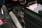
Main loom passes through bulkhead behind the engine bay fuse box next to the battery140 views
|
|
|
|
|
|