| Search results - "lr3" |
my lr3106 views
|
|

Lining Up Before the Event375 views10 trucks in all - 2 Heavily modded D2s, modded 03 D2, 90' RRC, lifted P38 on ATs, my LR3, modded D1, an older CJ, a Rubi that joined, and a Series III!
|
|

1979 views
|
|
2899 views
|
|

2426 views
|
|

I love the wet elements..., )528 views
|
|
2334 views
|
|

2843 views
|
|

2550 views
|
|

2156 views
|
|
On the test track496 views
|
|

2304 views
|
|

Vroom on snow534 views
|
|

2465 views
|
|

idea139 views
|
|

2320 views
|
|

2413 views
|
|
2530 views
|
|
2407 views
|
|
2593 views
|
|
2639 views
|
|

2672 views
|
|

2227 views
|
|

Picture by \'X\' for calendar222 views
|
|

2356 views
|
|

2209 views
|
|

2080 views
|
|

2256 views
|
|

2359 views
|
|

1914 views
|
|
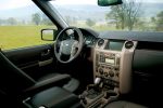
5156 views
|
|

4891 views
|
|
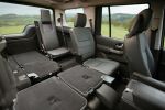
5211 views
|
|
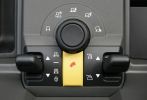
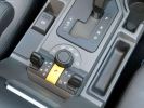
Terrain Response Switchgear2378 views
|
|
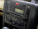
5657 views
|
|
4519 views
|
|
4480 views
|
|

09 D3 headrest DVD78 views
|
|
167 views
|
|

Dettaglio LR329 views
|
|
132 views
|
|

Muddy LR3 at US SUV of the Year Awards3659 views
|
|
157 views
|
|
159 views
|
|

super extended mode166 views
|
|
198 views
|
|
166 views
|
|

147 views
|
|
Thread upload9 viewsImage uploaded in new thread
|
|
Thread upload12 viewsImage uploaded in thread 79090
|
|
Thread upload15 viewsImage uploaded in new thread
|
|
Thread upload15 viewsImage uploaded in thread 79090
|
|
LR3 V8 SE785 views
|
|
Thread upload2 viewsImage uploaded in thread 5
|
|
Thread upload1 viewsImage uploaded in thread 5
|
|
Thread upload7 viewsImage uploaded in thread 137258
|
|

Thread upload7 viewsImage uploaded in thread 137258
|
|
Thread upload8 viewsImage uploaded in thread 137258
|
|
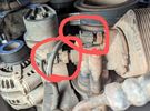
Thread upload2 viewsImage uploaded in new thread
|
|

89 views
|
|

114 views
|
|
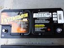
Deka 9A49 AGM Intimidator327 viewsThe Deka 9A49 AGM Intimidator makes an excellent primary battery alternative to the factory or Interstate. Made in US of premium quality. This is an excellent match with the Traxide system w/another Deka or Yellow Top optima.
This will behave properly in your D3/4 LR3 with slightly less wear and tear on your alternator.
|
|
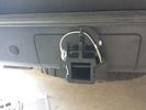
Rhino Hitch429 viewsCover fitted over the 75A Anderson plug with Rhino Hitch fitted which is a Class IV hitch. https://www.facebook.com/DifferentialPartsUS
Fits the Disco 3, Disco 4 and Range Rover Sport
|
|
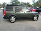
Tonga Green LR347 views
|
|
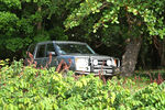
283 viewsCALENDAR 2011 ENTRY
This is in Puerto Rico. LR3 parked in the shade while we hang-out at a secluded beach that can only be accessed in 4x4.
|
|

179 views
|
|
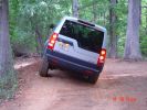
180 views
|
|
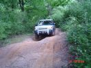
175 views
|
|

Rosen A7 \'alternative\' install459 views
|
|

24 views
|
|

Land Rover Aerial Fin images for both Glass and Metal Roof Disco3 / LR3863 viewsAs well as the two different fins, this pdf also shows the plastic blanking plate for glass roof vehicles where no fin is installed.
The glass roof fin is secured by two security screws from the top into a plastic frangible glue on gasket. The hope is that when struck, the fin will shear off and not crack the glass roof. Re the metal roof design, the fin is secured from underneath via two nuts.
The pdf also shows the various electrical bits related to the antennas. In the UK, the fin would house not only a cell phone antenna but the TV and satellite radio antenna electronics as well; in the States, the Sirius sat radio antenna and a G type cell phone antenna if the phone kit was installed would reside within the fin. The SAT NAV GPS antenna is located within the High Mount Brake Light plastic mounted to the upper rear hatch.
|
|
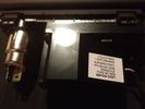
LR Aux Panel (rear)61 viewsBack of LR rear aux input panel
|
|
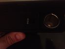
LR Aux Panel (front)68 viewsLR rear aux panel
|
|
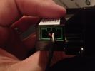
Aux Input Wiring Harness69 viewsUsed a modified PC CD interface cable to connect to stock female harness. Pins 3(R), 4(L), 5(G)
|
|
Avatar182 views
|
|
Thread upload6 viewsImage uploaded in thread 162372
|
|
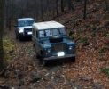
One of the trails at George Washington National Forest - Harrisonburg, VA139 views
|
|
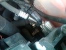
Breather Cap Installed2006 viewsThe black L shaped tube is is the Gore manufactured, (the Gore-Tex people), LR4 Breather Valve installed in an LR3. Naturally the installation looks similar to what one sees on an LR4 or RRS as the Gore breather valve is now OEM for new production.
The part number of this upgraded front differential breather valve is LR019450 and costs about thirty dollars.
|
|
Thread upload1 viewsImage uploaded in new thread
|
|
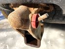
Thread upload1 viewsImage uploaded in new thread
|
|
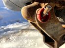
Thread upload3 viewsImage uploaded in new thread
|
|
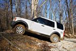
Climbed right up the hill with no hesitation whatsoever, I was shocked, because it took my Dad\'s F150 three tries and a lot of speed to get up it...103 views
|
|
84 views
|
|
76 views
|
|

75 views
|
|

75 views
|
|
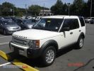
LR3102 viewsC6169014_1.jpg
|
|

LR3106 viewsC6169014_3.jpg
|
|

Thread upload3 viewsImage uploaded in thread 184519
|
|
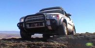
LR3 crests Carinya Flinders Ranges399 views
|
|

LR3 gets its first dust bath405 views
|
|
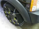
Snow Chains Installed - Land Rover LR3HSE94 viewsSnow Chains that seem to fit a Land Rover LR3HSE
|
|
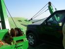
All at sea in an LR3105 viewsThe ferry from the mainland to Mazira Island was packed to the gunnels with vehicles. My LR3 was last on and they left the bow doors partially open for 14 lonnnnng sea miles across the Arabian Gulf!
|
|
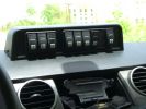
Mud UK switch binnacle453 viewsToo many switches for the roof mounted console, so this binnacle from Mud UK (desigend for the Defender) is an almost perfect match for the leather finished dash in the LR3. Switches, connectors etc bought from them too. From L - R switch functions are:
LH side mounted rack lamps
Driving lamps rack mounted
Spot lamps rack mounted
Bumper mounted driving lamps
RH side mounted rack lamps
Warn winch isolator
Rear mounted rack lamps (reversing)
Telescopic work lamp (fitted behind RH spare wheel)
|
|

194 views
|
|

Discovery 3 TDV8101 viewsSaw this on the UK Land Rover site on 23 oct 2007.
|
|

LR358 views
|
|

LR349 views
|
|
70 views
|
|

73 views
|
|

241 views
|
|
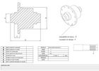
Differential size122 views
|
|
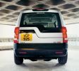
Mocked up LR3 with web site sticker708 views
|
|
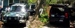
2004 D2, 1996 D1, 2007 D3260 views- possibly last reunion of all 3 as D2 goes to Minnesota, D1 stays in NC, LR3 goes to Seattle.
|
|
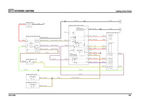
Lighting Wiring jpg58 views
|
|
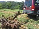
LR3 to plow your garden297 viewsI found this jpg where a current LR owner is using his LR3 for a similar purpose as the original Series units were designed to do - that is serve as a tractor for plowing a field or I suppose a garden.
In this case, I note the hitch is one of those that attach to the factory tow loop, (Rhino Hitch), rather than the factory product that inserts from the bottom and hangs down - (like a plow), but all the time. One of the other jpg's in this album shows the two factory variations plus a third jpg shows a closeup of the Rhino Hitch.
|
|
Thread upload5 viewsImage uploaded in thread 157786
|
|

Thread upload6 viewsImage uploaded in new thread
|
|
Thread upload6 viewsImage uploaded in new thread
|
|

Thread upload5 viewsImage uploaded in new thread
|
|
My LR3 taking a shower230 views
|
|
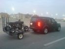
My LR3 & Modified ATV288 views
|
|
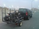
My LR3 & Modified ATV230 views
|
|
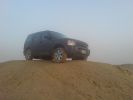
Muddy LR3255 views
|
|
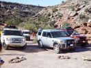
Goup of LR3\'s on Klondike Bluffs209 views
|
|
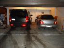
The garage. Land Rover LR3, Subaru Impreza 2.5RS and Honda VFR800 VTEC63 views
|
|

LR3 4.4 V8128 viewsDSC02863.JPG
|
|
LR3 4.4 V8124 viewsDSC02865.JPG
|
|
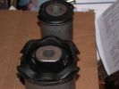
Lower Control Arm Bushings LR3 USA104 viewsLower Control Arm Bushings LR3 USA
|
|

First Discovey 3 off the line (US Spec LR3)424 views
|
|

First Discovey 3 off the line (US Spec LR3)382 views
|
|
First Discovey 3 off the line (US Spec LR3)450 views
|
|
First Discovey 3 off the line (US Spec LR3)621 views
|
|
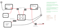
20 views
|
|

Fluid, Filter/Pan Combo removal and install5979 viewsThese are the LR instructions re removal and install of the plastic pan/filter combo for the ZF 6HP26X transmission on the 4.4L petrol V8 LR3.
The instructions tend to ignore the reason you have to lift the right hand side of the engine about 40 mm. This is because of a frame cross member that interferes with dropping down of the plastic pan. The real problem is a vertical "oil filter spout" that rises out of the filter/pan combo up into the transmission. The spout is the suction pipe for filtered transmission oil back up into the tranny.
On the metal pan versions, the filter is separate from the pan, hence the filter remains with the tranny when the metal pan is dropped. The filter is then removed or installed independent of the metal pan, hence with the metal pan, there is no need to lift the engine.
If one is removing the plastic pan so as to install the metal pan, then some do not lift the engine but just drop the plastic pan enough to gain access to saw off the vertical plastic spout - it is a one time procedure.
Be aware however that the metal pan uses a flat gasket and the plastic pan uses a O ring like perimeter gasket that sits in a half round groove in the tranny casing. Also the metal pan uses 21 shorter torx M6x22.5 metric cap screws for the perimeter bolts. The plastic pan uses longer M6x28.5 torx metric cap screws.
|
|

Exploded Parts view calling up 6R60/80 and 6HP26/28 variations3113 viewsThis single page jpg exploded parts view indicates some commonality between the Ford and ZF versions of the early and later six speed units. Technically this sheet is for the RWD units as there are variations between plain RWD units, 4WD, and AWD. The transmission in the LR3 is called by ZF to be a 6HP26X and by LR in some publications, the 6HP26
|
|
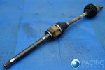
Thread upload34 viewsImage uploaded in thread 163443
|
|
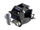
Thread upload16 viewsImage uploaded in new thread
|
|

Thread upload1 viewsImage uploaded in new thread
|
|

Thread upload12 viewsImage uploaded in new thread
|
|
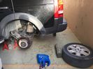
Thread upload9 viewsImage uploaded in new thread
|
|

Thread upload8 viewsImage uploaded in new thread
|
|
Thread upload11 viewsImage uploaded in new thread
|
|

LR390 viewsGetAttachment.aspx4.jpg
|
|
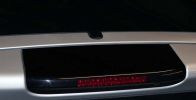
GPS receiver on the US DS/LR3390 views
|
|
Thread upload11 viewsImage uploaded in new thread
|
|
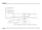
Horn Wiring Image58 views
|
|

Horn Wiring71 views
|
|

Rear Spoiler Fitting Instructions LR131 views.
|
|

Tailgate Spoiler170 views
|
|
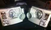
Finished project75 viewsScary start but the end result is AWESOME!!
|
|
LAKs LR3428 views
|
|

Headlight mod82 viewsQuick preview of painted reflectors behind the lens
|
|

Headlight mod77 viewsNo turning back now..
|
|

Headlight mod79 viewsAlot of hours for alil prep work..
|
|

Headlight mod88 viewsAmber lens was quick to dissappear..
|
|

Headlight mod266 viewsHeadlight mod to my07 land rover discovery 3
|
|
LR364 views
|
|
Nieuwe LR3 maart 200883 views
|
|
Brand new blinking Discovery359 viewsDad is very happy with his new car, but mine daughter is more than proud and wil make a blinking picture. This is the first and only day to have a blinking Discoevery3.
Rene@LR3.nl
|
|
My-LR349 views
|
|
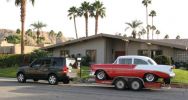
Towing my 56 Chevy264 viewsI towed my Classic Chevy about 650 miles from Palm Springs to Reno, including over the Sierra Nevada mountain pass (7,085 feet (2160 meters)) and the LR3 pulled very well.
|
|
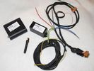
LR3 Bundle & cable harness70 views
|
|
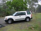
MY TDV6 LR3 at Patterson154 views
|
|
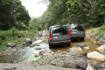
Twins283 viewsCALENDAR 2011
After comming down a nasty rock trail, we found the place we were looking for... This is in Puerto Rico. My LR3 was 3 weeks old! (got permission form the other owner to publish foto), feel free to edit foto.
|
|
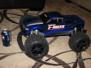
32 viewsNew Christmas toy to try to learn the finer points of speed control over obstacles... Now I just need an LR3 body that will fit this monster...
|
|

Proud new owner of my LR3356 views
|
|
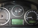
incredible65 viewsonly 8,7 lt/100km
|
|

Replacement switch from RRS installed on LR3864 viewsThe switch shown is LR part number YUZ500020, the upper rear hatch release switch that is found on the Range Rover Sport.
The switch body is the same switch as on the LR3 except that there is no wiring disconnect on the LR3. Hence when the switch corrodes and requires replacement, the LR solution is to purchase a new handle and license plate light assembly. I instead cut off the old switch and installed a JAE mating connector to the existing wiring and hence just plugged the RRS switch in.
The replacement RRS switch snaps into the same rectangular space in the same manner as the removed LR3 switch, the difference is the JAE male wiring connector.
|
|

85 views
|
|
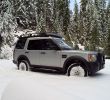
A trip in the snow606 views20 mile round trip in fresh snow - no problem!
|
|
45 views
|
|

54 views
|
|
65 views
|
|

Thread upload9 viewsImage uploaded in thread 140629
|
|

Thread upload7 viewsImage uploaded in thread 140629
|
|

Thread upload7 viewsImage uploaded in thread 140629
|
|

Thread upload14 viewsImage uploaded in thread 55010
|
|
My LR3134 views
|
|

Thermostat Housing LR005631538 viewsWhen the time comes to install a new thermostat, consider installing the whole housing instead.
Advantages are the thermostat is correctly installed, (not as simple as it should be); you get all new plastic and that is important, plus a new coolant temperature sensor and also a new heater coolant bypass valve, the secret part no one realizes is also within.
The cost of the whole assembly is not much more than the cost of a factory thermostat and the effort to replace all is not as difficult as it might seem.
|
|
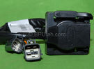
Harness section that runs behind the rear bumper.410 viewsThis is the harness section that clips up inside the rear bumper and includes the circular 7 pin, (6 flat +1 round), NAS socket, and also the 4 pin NAS flat connector.
The two small plug ends connect under the rear left tail light to the harness section that exits from the interior.
The Land Rover part number for the NAS trailer tow kit, (both cables), is YWJ500220.
|
|

Harness that connects inside left rear compartment.445 viewsThis is the harness section that connects behind the left rear interior access panel and exits thru the large grommeted hole to below/behind the left rear tail light.
Note the two rubber grommets on the harness as there is both an interior metal skin and an exterior metal skin behind the left tail light assembly.
The two light grey connectors plug into two existing connectors near the top of the rear left interior access panel. The two darker connectors plug into the second piece of harness.
There is no little separate fuse box either with the NAS spec harness. The fuse box is included with the UK 13 pin dual plug units. If there was a fuse box, it would be on this portion of the harness.
|
|

Land Rover LR006482 replacement sounder10 viewsThis is the official Land Rover replacement sounder, part number LR006482 and costs about double the Ford part number sounder. I used the Ford sounder and it sounds the same as the original factory sounder in my 2005 LR3.
|
|

LED trailer lights adapter for LR3843 viewsThis doc includes a partial list of materials and the instructions/links required to construct an adapter to prevent LED trailer lights from pulsing due to the 3's diagnostic circuits interrogating the signal light circuit.
Using the adapter also facilitates the green flashing of the dash located trailer indicator when the signal lights operate plus inhibits operation of various systems such as the backup sensors, etc.
|
|
lr3 needs bigger tires20 views
|
|

LR Electric Trailer Brake C2590 Female Connector606 viewsThis female connector, C2590, located up above and near the brake pedal is for the Trailer Electric Brake Controller hookup.
The Black wire in the bottom right is pin #3, the ground. The Blue wire to the left is pin #6, the Trailer Brake Controller output going to the rear trailer socket.
The White #4 wire is the 30 amp fusible link, (Link 6E in the engine compartment junction box), for the Brake Controller 12VDC power feed from the battery. Note that this would make a pretty good power source for CB radios and the like if no electric trailer brakes were required.
Pin #5 is a Green wire from the stop lamp switch, (the control input for the Brake Controller).
This plug is standard on all NAS (LR3) vehicles, but unlikely to be found on the D3 spec units.
|
|
Day of delivery - Mon 30 Jan 2006389 views
|
|
Gold Mountain Trail52 views
|
|
Gold Mountain Trail43 views
|
|
Gold Mountain Trail46 views
|
|
Gold Mountain Trail53 views
|
|
184 views
|
|
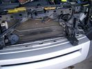
19mm wiring loom in trough behind bumper and in front of rad792 viewsThe 19mm wiring loom is large enough that a maximum of six 6mm air lines can be fished thru as required. The loom runs from the FASKIT panel located in the engine compartment behind the left front headlight, down and across in front of the rad and then down to the front axle valve block located behind and below the right fog light.
|
|
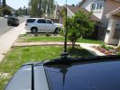
348 viewsAntenna Mount
|
|
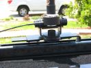
327 viewsAntenna mount.
|
|
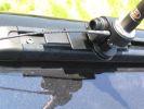
335 viewsHere is the antenna mount on the roof rack. The black aluminum bar is custom made to hold the antenna mount.
|
|
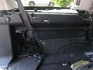
372 viewsHere is the left rear trim panel removed. GTR proved useful in the removal process! The cubby box snaps on to the top of the panel.
|
|
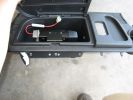
414 viewsHere is the left rear cubby box with the TM-D700A bolted inside. I also drilled a hole in the bottom of the cubby for antenna, GPS, and power wiring, and a hole in the front for control, microphone, data, and audio cabling.
|
|
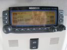
461 viewsCompleted install of control panel.
|
|
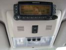
388 viewsCompleted Install of Control Panel. Wiring goes up into headliner, over curtain airbag on left hand side, and down the B pillar.
|
|

LR3 Air Conditioner Drain Tubes behind centre console2131 viewsThis shows the two air conditioner drain tubes located left and right under the radio stack.
The tube on the left side, (steering wheel side, LHD), disattached itself and the carpet on the floor under the gas pedal etc became soaked. I think rain water from outside that comes in the outside cowl vents also exits via the tubes as I first noticed the carpet was wet after parking outside during a big rain storm.
It was relatively easy to slide up and reattach the rubber hose that runs from the rectangular shaped plastic discharge hole(s) of the heater "pan" down along the transmission hump area and thru the floor pan. There is a hose on each side of the transmission hump, but only one hose had let go on my 3. The rubber hoses just slide over the rectangular plastic openings of the two heater housing drain outlets.
To get at each drain hose, remove the vertical sort of triangle carpeted piece below each side of the radio stack. The triangles of carpet will just pull away as each is held on with those metal U clips Land Rover so likes. Dislodge each triangle at least sufficiently to get ones hand in to slide the rubber hose back on.
You will rarely see AC water on the ground as the front drains pour onto a metal underside protection skid plate and the rear drain onto the top of the left rear muffler.
|
|
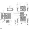
Block Diagram of Disco 3 / LR3 Air Suspension System.1552 views
|
|

Air System Schematic with parts identified.1374 viewsAir system block diagram with components numbered and identified.
|
|
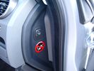
Air Suspension ECU Fuse 35P cut off switch.3820 viewsThis shows the SPST rocker switch mounted in the blank plate installed in lieu of a manual passenger side air bag shut down switch - now automatic via passenger seat pressure switch. Fuse 35P (5 amps) is located in the interior fuse box behind the lower glove box and protects the ignition power supply to the Air Suspension ECU. When the SPST switch is moved to the OFF position, the RAISE /LOWER switch on the centre console is not powered, and hence does not function. As such, some signals from the wheel height sensors and CPU are ignored. By itself however, removing F35P will probably not stop the 3 from self dropping, particularly after the engine is turned off.
Fuse F3E, (5 amps), located in the engine bay fuse box by the starting battery protects the circuit that provides feedback to the Air System ECU indicating that the Compressor Relay has successfully operated and that the Air Compressor is or should be operational, can also be removed, (but is probably not totally necessary), as it gets its power thru F26E. Hence Fuse F26E, (20 amp), also located in the engine compartment fuse box is the fuse that must be removed. This fuse protects the circuit that provides full time battery power to the Air System ECU. When in place, current thru the fuse powers the periodic re-levelling action, (usually lowering a bit with that brief air release noise), that often occurs when the vehicle is parked and the engine is off.
Removing F26E fuse will stop the auto levelling action and also inhibit any other down to the stops signals, (engine running or not). When F26E is removed, no power can flow thru to F3E, hence removing F3E is more for insurance than an absolute requirement. The same with F35P, removing F26E removes primary full time power from the Air Suspension ECU, and hence removing the F35P fuse should not really be required either as long as F26E has been removed.
|
|
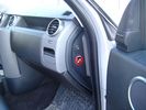
Air Suspension ECU Fuse 35P Shut Off Switch2635 viewsA more distant view of the shut off rocker switch in the ON position which is the normal position for when all is working as Land Rover intended.
Ideally, (but not totally necessary), the F35P circuit should be powered or de-energized after the various computers have gone to "sleep".
Similarly, removal of the F26E or F3E fuses is preferable after the computers have all gone to sleep but it appears that no real damage will be done if the fuses are removed while the system is energized. Pulling F26E is the main full time fuse that powers the air suspension computer. As such, once F26E is removed, pulling F3E is not really required.
Power for the compressor goes thru the 60 amp fusible link and relay, however control of the relay is via the air suspension computer so depowering the air suspension computer effectively depowers the air compressor and the internal exhaust valve relay/port.
|
|

LR3 Antennas PDF122 views
|
|

Battery Maintainer pigtail sticking out of Grill726 viewsThis is all you see when everything is put back together - just the pigtail and Weather Pack blanking plug. Most often, I have it all tucked back behind the grill.
In winter, there may be a second cord hanging out as well - the 120 VAC power cord for the engine block heater, a tea kettle like element inserted in the engine block. NAS petrol V8's do not have the Fuel Burning Heater, (FBH), installed, but instead in cold area markets have the block heater element assembly available as a dealer installed option. There is an argument to say that the heating element is factory installed in all cold climate V8 gasoline engines, however the appropriate power cord is not. If true, this means that all one needs to purchase is the area specific power cord and plugging in / attachment to the engine block located block heater.
As such, you will often see a conventional 120VAC three prong power plug hanging loose out of the grill of most vehicles here in the wintertime. In summer, most drivers tuck the plug back behind the grill as it is no beauty mark.
|
|
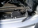
Battery Maintainer switch box and connector 722 viewsThe Hammond box contains a DPDT toggle switch with centre off. The Positive and Negative from each battery feeds to the switch. Depending on the setting of the toggle, (full left, full right,or centre off),the respective batteries connect into the pigtail that can stick out thru the grill when one wishes to connect the charger.
This allows one to charge each battery independently via a suitable battery maintainer. I use a CTEK unit that feeds a maximum of 3.3 amps at 14.4 or 14.7 VDC, depending upon setting. The wiring therefore allows for a slow recharge of either of the batteries separately if either one requires such.
|
|
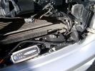
Battery Maintainer switching box plug and CTEK Multi US 3300 charger. 706 viewsThe CTEK Multi US 3300 maintainer is just sitting there for the picture. In addition to topping up both batteries, the CTEK can provide power such that if the batteries were completely dead, there would be power to the door locks and hence, one could most likely still gain access via the remote once the starting battery charged up a bit.
The Land Rover recommended method is via the hidden key hole which is mechanical, however that presumes the mechanism is not frozen from lack of use. As such, the manual lock should be exercised at least once a year to ensure that it still functions.
The blanking plug sitting on top of the plastic box is of the GM Weather Pack series. That is what I like to use for vehicle wiring that is subject to moisture, (or not).
|
|

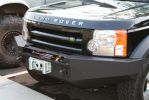
ARB bull bar example403 views
|
|
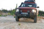
front of lr3 with ARB bar337 views
|
|
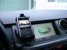
BlackBerry Tour 9630 mounted on air vent265 viewsThe antenna amplifier is mounted lower near the steering column. The amplifier box is painted black but looks sort of gold coloured due to the lighting in the other jpg showing the amp located under/near the steering column.
|
|
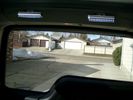
Boot lighting, looking to rear - hatch closed 542 viewsView shows the lights mounted in the rear on an early spring day.
In operation, the lights are tilted so that they shine downwards. The lights are mounted high enough up that one cannot see the LEDs from the front thru the rear view mirror; also the LEDs are so directional, that no light is thrown on the side glass.
Each assembly contains 15 LEDs, however the reflector is such that the LEDs appear to double.
|
|
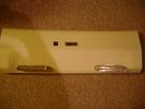
Boot lighting panel, finish side up 309 viewsThe above jpg shows the two 15 LED light assemblies as well as the SPST rocker switch mounted beside the W5W Land Rover supplied light.
The reality is that with the recent development of LED lighting that can replace a W5W T10 bulb, one can almost achieve the same results just by installing a LED bulb within the factory light.
|
|
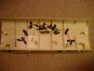
Boot lighting panel, wiring side up 281 viewsThis shows the back side of the plastic cover panel on which the two LED lights are mounted.
Also of note is the SPST rocker switch to switch the new lights off independent of the the Land Rover W5W light.
The new light pair will only power up if the Land Rover light is powered and hence dims and automatically goes off along with the Land Rover light.
The Black wire is ground, the Purple wire is +12VDC.
|
|
334 views
|
|
253 views
|
|
271 views
|
|
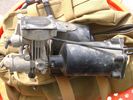
Compressor Air Drier 2044 viewsA view of the air drier - the black round thing to the right of the actual compressor cylinder head.
The general feeling is that the air dryer is responsible for most of the compressor problems now and that replacement of either the assembly or just the beads inside will probably revive one's compressor. In reality, the beads may have for the most part broken down and turned to dust plugging the internal filters. Hence replacement of the complete dryer unit has some merit.
The part number for the dryer assemble complete with the desiccant is VUB504700.
|
|
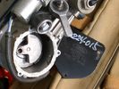
Compressor Con Rod Broken 1752 viewsThe model number of this compressor is RQG500060; the model number of my replacement compressor was LR015303, the unit that was apparently being installed on the D4 vehicles as of Spring 2010. As of Fall 2011, the new replacement part number is LR023964, the same as in the 4's.
Note the number hand written on the black plate. All the compressors seem to have some number hand written on them - hand built I presume, and every unit perhaps evolving a bit differently as LR struggles to build a compressor that will last. I guess Hitachi, (the manufacturer), should be given credit for that.
|
|
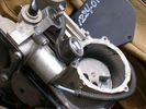
Compressor Con Rod Stud 1342 viewsVisible in the expanded view of this picture is the worn rounded threaded screw that tied the con rod bearing to the electric motor eccentric. I think the stud unscrewed itself and pulled out; then the piston jammed and the con rod broke.
|
|
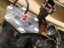
Compressor Electrical Plugs 1406 viewsThis shows the two electrical connectors; the two pronger is the power to the compressor, and the multi-pin connector carries control signals. Also the temporary red plug is where the 6 mm tubing from the centre valve block connects. This line carries both the compressor and exhaust air to and from the springs.
|
|
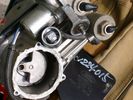
Compressor Exhaust and Inlet 1534 viewsThe two temporary black plugs cover off the 8mm and 10mm push fit lines to the air inlet and exhaust lines. Also visible is the worn threaded stud that I think was the initial failure mode.
|
|
offroad 98 views
|
|
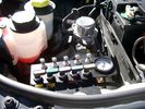
View of mounted panel from front left side877 viewsNote that all valve handles are shown in the OFF position, (the trouble position). In this case, the air that is in the air springs, (if any), is trapped in there - that is the valve blocks cannot vent whatever air is already in the air springs as the air lines between the springs and respective valve blocks are closed off by the FASKIT valves. In operation, there may be only trouble with one air spring, (perhaps a wheel height sensor), and as such, only one valve would need to be closed. If there was complete air compressor failure, then all valves would be closed and then as required, each spring could be manually filled from an outside clean dry oil free air source.
|
|
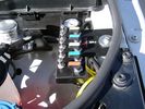
View of mounted panel from front left corner737 viewsI drilled a hole for the supplied 6 mm tie down toggle bolt in a flat portion of the wing on which the panel sits. I inserted a 50 mm flat rubber washer between the wing metal surface and the underside of the black painted panel plate; also a 40 mm flat rubber washer between the supplied fender washer and the metal plate - just seemed like a good idea so surfaces mate well even if wing metal not completely flat.
|
|
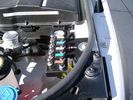
View from front left side looking towards rear aux battery compartment under cover 646 viewsAs there is no Fuel Burning Heater in the NAS V8 petrol vehicles, there is space available to install the FASKIT panel here. The piping is such that each air spring can be isolated from the air system and then filled one at a time manually via the Schrader valve. There are five Schrader valves and five shutoff valves. The fifth valve nearest the gauge controls air from the compressor, and can provide fill up air via a jumper fill line assuming the compressor is still operational.
|
|

Frazier Park54 views
|
|

Frazier Park50 views
|
|
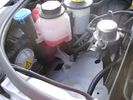
Empty space in NAS LR3 for location of FASKIT panel599 viewsThe empty space is available as the North America Spec gasoline engine LR3's do not have the Fuel Burning Heater installed. The air lines from the four air springs and the air tank will appear to rise up from under the headlight assembly. The lines to the front block valve assembly located behind the front right fog light will sort of run within the bumper across the front of the radiator down into behind the righthand fog light. The rear lines somewhat follow the path of the existing air feed line from the front valve assembly to compressor. Rather than be located between the left front fender liner and left metal wing however, the four lines will feed thru the empty wing space inside and above the wheel well arch and exit down by the left front mud flap. From there, the lines run along the left frame member above the air tank and then parallel the frame over top the compressor to the top of the rear left air spring where the rear air block valve assembly is located.
|
|

169 views
|
|
Holy Jim Trail82 views
|
|

Still Picture - grab from video to show full length interior rear sunroof198 views
|
|

225 views
|
|

Interior Video Showing Full Length Rear Sunrood inside rear165 views
|
|

Video Showing Full Length Interior Rear Alpine Roof323 views
|
|
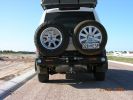
kaymay rear bumper/tire carrier493 viewsthis is on delivery to me.... ;) . it went on easily but i will have it modified to place right wheel more toward middle like disco II. i will only ever use the laft side for jerry can or something, not another tire. i don't like how right tire totally blocks main lamp.
|
|

Rear lamp guard fitting instructions406 views
|
|
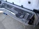
Dust Seal duct taped back together 2281 viewsThis shows the dust seal duct taped back together; also the surplus wire rope exiting from the actuator area prior to being cut to length.
I do not think the sticky plastic membrane is a dust seal, but more of a cable protector to cover up the wiring bundle that is effectively sticking to the underside of the flexible membrane.
|
|
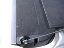
Flexible wire rope fishing leader 0.032" diameter exiting carpet 1948 viewsThis is all you see of the completed mod.
The short little angled "line" about an inch long that looks like a piece of debris and is located a few inches "above" the support cable is actually the wire rope release cable exiting from under the carpeted lift gate cover.
I drilled a very small hole in the carpet and pushed the 0.032" diameter release wire thru and then slipped the loose end under the black plastic.
To release with the lift gate etc closed, from the inside, just pull the loose end free from under the black plastic and gently pull wire about 5mm, (1/4"), and the upper door catch should release. You will have to manually push the upper door out wards to actually effect opening, but you will already be inside the rear cargo area so that part is easy to do.
The assumption is that the lower door latch still works electrically and hence, the lower lift gate half will open as normal by pressing the usual button on the top left of the lower door half.
|
|

Carpet Panel Removed showing Bass Speaker and Dust Shield 1733 viewsSomething is wrong with the orientation, however this shows what you see when the carpet is removed.
The dust shield, (under which the actuator is located), in the picture is as yet uncut. The white bit is the underside of the plastic lower lift gate carpeted cover panel.
The round thing is the woofer speaker for the Harmon Kardon radio. When the radio is working, one can see the speaker moving, but not much bass sound actually seems to emanate from the speaker.
|
|
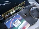
0.032" OD metal fishing leader and lead fishing weight clamped to existing wire rope 2120 viewsI used a size #0 lead fishing weight as a clamp to attach the 0.032" diameter flexible wire rope fishing leader to the release cable.
The pictured weight is the smaller #00 weight, however it did not work very well so reinstalled with the larger #0 size. I clamped to the cable as what breaks is the L retainer that is hidden in the actuator and holds the cable. When the L breaks, it lets go of the cable so you hear the clicking but there is no opening action.
Clamping on to the cable is an attempt to resolve that reality; also if the actuator electrically fails, the release mod should still do the task. Note in the picture the two Torx T15 screws that hold the gold plate to the plastic case and also the two 8mm cap screws that have to be loosened to remove the actuator from inside the door.
|
|
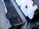
Carpeted cover removed showing uncut dust seal and underside of carpeted cover. 1628 viewsNote that there are all sorts of electrical wires sticking to the underside of the dust shield - so be very careful when you cut thru the shield.
I used a box knife very slowly and was surprised at how many conductors there were running just under the shield membrane.
|
|
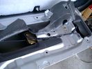
Dust seal cut; note electrical conductors right under dust seal 1627 viewsShows what is underneath when the dust seal is cut. Note the electrical conductors.
I used a box knife to cut the plastic and it was at first easy; then I seemed to hit something and fortunately I stopped - it was the wires - lots of them stuck right to underside of the sticky seal material.
Also shown are the two 8mm nuts in slots that you only have to loosen to release the gold actuator assembly.
|
|
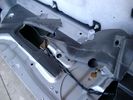
Dust seal rolled back showing electrical conductors 1658 viewsNote power conductors just under the dust seal which makes cutting the seal more interesting.
Also shown are the two 8mm nuts located in slots. One must loosen each nut to effect removal of the actuator. This will then reveal two T15 Torx screws that one must completely un-thread to remove the top gold plate from the actuator assembly.
|
|

NAS 7 Blade Round plus NAS 4 Pin Flat Vehicle end Socket527 viewsThis shows the function of each blade when looking into the connector at the vehicle end for the 7 pin NAS plug. The layout is the pin order for most new North American pickup trucks and the LR3/4.
The colour and gauge of the wires feeding into the back of the plug varies even within manufacturer model lines.
Also detailed is the flat 4 pin layout common on smaller trailers not having electric brakes. This includes most U-Haul rental trailers.
|
|

NAS 7 Pin Round Socket + 4 Pin Flat Socket oriented as installed.752 viewsThis is the layout you see when you look into the NAS Land Rover sockets as installed at the rear of the LR3/4. The flat 4 pin socket is located under the round socket.
Wiring order is relative to the slot on the round socket, and hence the same as the other jpg where the slot is shown at the top.
The CJB monitors the front and rear turn signal lamps and can detect if more than four lamps are fitted, (the side turn signal lamps are not monitored). This is another reason for using genuine LR bulbs as off shore bulbs can have varied and out of spec resistance values.
When a trailer is detected, the trailer warning indicator in the instrument cluster is supposed to flash green in synchronization with the turn signal indicators.
If one or more of the turn signal lamps on the vehicle or the trailer are defective, the trailer warning indicator will cease to flash any longer. This is to alert the driver to probably bulb failure.
If the trailer has LED lamps installed, and no LED adapter circuitry is used, most likely the trailer will not be sensed and systems such as the backup sensors will not be disabled.
|
|
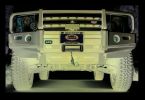
275/70R17 MTR teaser429 views
|
|

LR3 Parking Space80 viewsMy car was pooping mud all night long from my countryside escapade. :)
|
|
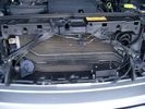
Plastic cover and Box back on in Front of Radiator 637 viewsThe wiring loom is below the cover - nothing is crushed or distorted and all fits back together OK. The black plastic box with the DPDT, (centre OFF), toggle switch is to tie the battery maintainer to each of the two batteries per the Traxide Dual battery install. I can also get power to the power door locks if all fails.
|
|
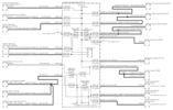
Power Window Circuit centered on Central Junction Box (behind glove box fuse panel)733 viewsRelay 143, the power window relay, and most other relays and FET's as well are built into the back of the passenger side behind the lower glove box fuse panel.
As such, the relays etc are not removable, jump-able, or serviceable.
|
|
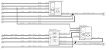
Power Window Circuit Sheet 2 Central Junction Box to Passenger Front Switch365 views
|
|

Power Window Circuit Sheet 3 Central Junction Box to Rear Switches391 views
|
|

Component Names related to Power Window Wiring Diagram283 views
|
|

Power Window Components474 views
|
|
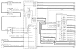
Power Window Circuit Sheet 1 from Battery to Central Junction Box (fuse box behind glove box)352 views
|
|

LR3 Production Line 171 views
|
|

LR3 Production Line 263 views
|
|

LR3 Production Line 362 views
|
|

LR3 Production Line 458 views
|
|

LR3 Production Line 360 views
|
|

LR3 Production Line 657 views
|
|

352 viewsarticle from Quatroruotte June 2005 - 5 golden stars for offroad
|
|

193 views
|
|

339 viewsQuatroruotte June 2005 - some results from the tests
|
|

208 views
|
|

245 views
|
|

221 views
|
|

328 viewsvarious road tests
|
|

202 views
|
|
LR3 00135 viewsmy lr3
|
|
In the water on Baby Lions Back302 views
|
|
The Crack on Klondike Bluffs407 views
|
|

Possesed on Hells Revenge264 views
|
|
Hells Revenge294 views
|
|

The Bath Tub on Hell\'s Revenge245 views
|
|
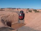
Into the Bath Tub on Hell\'s Revenge377 views
|
|
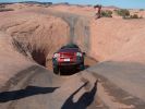
Out of the Bath Tub on Hell\'s Revenge378 views
|
|
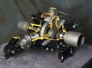
Rear Differential cutaway with E-Locker 1210 viewsThis jpg is from the link below.
There are another ten or so cutaways plus a whole file group showing a 2005 LR3 sectioned for the 2005 Chicago Auto show. Each jpg has an enlarge function to the bottom right of a main picture.
On one jpg you can see right into the stepper motor.
http://www.cutawaycreations.com/cutaways.php?project=land-rover-electronic-rear-differential#/IMAGES/car4/images/image1.jpg
Both the front and rear differentials are manufactured by Dana Spicer in the UK. Dana calls them a Clamshell design.
|
|

LR3 Electrochromatic Interior Rear View Mirror wiring diagram.852 viewsIt seems that there are two fuses, F69P and F5P that provide power for the interior rear view mirror. Ten amp F5P is a feed off the reverse gear relay and inhibits auto dimming when reverse is selected. Five amp F69P provides power to the auto dimming circuits and the garage door opener function if optioned.
The pdf can be downloaded and printed out. For on screen viewing, right click on the pdf and select the Rotate Clockwise button.
|
|
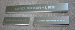
LR3 sill plates279 viewsLand Rover - LR3 sill plates for US market
|
|
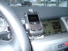
Blackberry Tour mounted on air vent showing default analogue clock 213 viewsA characteristic of the Blackberry is that when charging, the display can default to an analogue clock. Hence when the unit sits in the holder, the phone is being charged and the analogue clock displays. When the phone rings, the clock disappears and the call id displays.
|
|

LR3 Sparkle Silver 6 spoke Wheel Cromodora of Italy 19 inch x 8 ALY72191U1108 viewsThese are the standard equipment 19" wheels on the 2005 LR3 HSE. The wheels are Made in Italy by the Cromodora company. Each are rated at 940 kg (2,072 pounds) and have an offset of 53 mm positive, (53P or +53).
I mention the 940 kg load rating as that is about the heaviest rating of any Land Rover product. The RRS and RRHSE both have lower ratings. What this means is that while a wheel from a Range Rover may physically fit, it probably does not have the brute strength of the factory spec Land Rover 3 wheel. There is no Land Rover product heavier than the 3, hence the 3 wheel design spec is the heaviest of the bunch.
|
|

LR3 Sparkle Silver 10 spoke Wheel Cromodora of Italy 18 inch x 8 ALY72190U727 viewsThese wheels are factory standard on the 2005 LR3 SE and Made in Italy by the Cromodora company. Each wheel is rated at 940 kg (2,072 pounds) and has an offset of 53 mm positive, (53P or +53).
I mention the 940 kg load rating as that is about the heaviest rating of any Land Rover product. The RRS and RRHSE both have lower ratings. What this means is that while a wheel from a Range Rover may physically fit, it probably does not have the brute strength of the factory spec Land Rover 3 wheel. There is no Land Rover product heavier than the 3, hence the 3 wheel design spec is the heaviest of the bunch.
|
|

Wheel cut thru definitions and specs898 viewsNote the location of REAR SPACING and also OFFSET; probably two of the most important dimensions and not always understood as related to wheel size and relationship to the brake components.
For the 3, Rear Spacing is approximately 6.5 inches or 165 mm for a nominal 8" rim. Offset is 53P or 53mm Positive, which means the distance from the machined hub flat mounting surface to the rim's true centreline is 53 mm in the outboard direction. (The rim illustrated has a negative offset.)
As Positive offset increases, this means the wheel wraps around the disc brake mechanism more deeply, and hence the more the wheel would cover the brake parts. This is why most 18" wheels will not fit with the larger Brembo "supercharged engine" brake calipers.
Pitch circle diameter is 120mm; Pattern is 5 lug, and the tyre load rating is 112 with a recommended tyre speed rating of H or higher along with the XL load rating. For the 3, the stock tyre diameter is about 30 inches. The 255/60/18 or 255/55/19 OEM tyre outside diameter is 30.04 inches; Wheel lug torque is from 130 to 150 Nm or 96 to 110 lbf-ft and the lug nut hex socket size is 22mm.
Max Load High Speed Driving Tyre pressures are Front, 33 psig, (230 Kpa) and Rear, 42 psig, (290 Kpa).
The OEM rims are rated at 940 kgs, the highest that LR makes, hence while rims from other Land Rover products may physically fit, the odds are they are under rated in a weight sense.
|
|

Underhood Fuse and Relay Box drawing 3054 viewsShows the various fuse and relay locations. Fuse 3E, (5 amp), and Fuse 26E, (20 amp), as well as upgraded 70 amp Relay 7, part number YWB500220, locations are displayed. Relay 7 sends battery power to the compressor from the 60 amp fusible link called up as 10E. Fuse 26E is what provides full time always on battery power to the air suspension ECU and hence powers the auto level wakeup when the vehicle is shut down and say parked for the night. Removing F26E is the primary method to disable the air suspension system; Removing F35P is more if you want to experiment with it from inside.
I found it useful when I had a suspension problem, (actually a wheel alignment problem picked up by the steering wheel angle sensor), that only showed itself on the highway but allowed for no trouble light driving in the city. This was because in the city, the steering wheel was always in motion and rarely was the vehicle driven in a near straight line for very much distance.
|
|

61 views
|
|

Brits and their tea!106 viewsWhenever there's a problem to solve - put the kettle on. After running out of fuel, 18km from the nearest balcktop and fuel station, 3 of the team's cars waited for the return of the other two with fuel. What does one do at times like these? Have a nice tidy up inside, dust off the sand and put the kettle on for a cuppa tea.
|
|
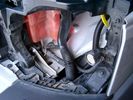
19 mm wire, (tubing), loom rising from below at left headlight656 viewsFrom the FASKIT panel, five air lines fit in the 3/4" (19mm) wiring loom and feed to the front air valve block located behind and under the right front fog light.
|
|
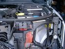
Wiring (tubing) loom at left headlight showing FASKIT panel 584 viewsThis shows the wiring (tubing) loom and FASKIT panel mounted to left wing. The loom moves a a couple of inches (50mm) towards the bottle once the headlight is put back in as there is not enough free space for the loom as located. The FASKIT panel is just visible at the top left corner of the picture.
|
|
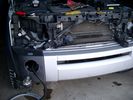
Wiring, (tubing), loom exiting temporarily from the front right fog light.569 viewsThe front axle air valve block is located just behind and below the fog light. Access to the valve block is by removing the right front fender liner, (or the bumper). The FASKIT lines are attached to the left and right front air spring lines at this location; also compressor air is taken from this location as well. Cutting the lines at as few different locations makes it easier to find leaks at a later date. As above, five 6mm air lines run from the FASKIT panel to the front axle air valve assembly and run within the loom. Two pair of the lines are for control of the air springs, and the fifth line taps the air supply at the valve block assembly off the compressor. This will be the air source line rather than tapping in directly to the high pressure air tank.
|
|
Wire (tubing) loom on right to down into bumper 464 viewsThis shows the 19mm loom in the trough between the bumper and the rad as it drops down into the right fog light area.
|
|
Thread upload13 viewsImage uploaded in thread 140430
|
|

LR3 At Home Day 1115 viewsDay 1 of LR3 ownership
|
|
In the Showroom104 viewsDelivery Day
|
|
My first expedition and already an expert.111 views
|
|

Thread upload3 viewsImage uploaded in new thread
|
|

arbbumper359 viewsHere I used the ARB bumper to protect the side of the LR. Had I gone in straight it would have damaged the sides (did it later on the trail :-( )
|
|
Thread upload7 viewsImage uploaded in new thread
|
|

55degiphone323 viewsHere is the proof... I had calibrated it before the event started...
|
|
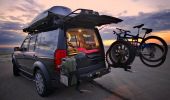
Badlands-SD, bike/tire carrier is kind of cool actually.429 views
|
|

Thread upload21 viewsImage uploaded in thread 119437
|
|

Thread upload20 viewsImage uploaded in thread 129655
|
|

Chassis mod594 views
|
|

Dirty LR3387 views
|
|

PTI Bluetooth HTC HD2 combo60 views
|
|
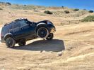
Thread upload2 viewsImage uploaded in new thread
|
|

Thread upload1 viewsImage uploaded in thread 160307
|
|
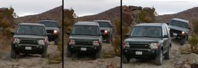
Smooth off road ride!399 viewsThis was the first time I took my LR3 off-road. I traded my Jeep Wrangler for this vehicle so I was used to heading into the rugged mountains. I was very amazed (as were my friends in their Jeeps) just how level the LR3 remained as I navigated over various dips and mounds. You can see the Cherokee behind me couldn't say the same.
|
|

lr3-kaymar-closed with 20"405 viewsthe kaymar carrier, designed to allow two tires, sets them both a bit outboard, thus blocking the lamp. that\'s when I realized why they put the fully functional lamps in the bumper (functions: running, brakes, signals, hazard)
I plan to re-weld the locating section more towards the middle of the rear similar to Disco II orrientation.
|
|
Reach Dam-front right328 views
|
|
Reach Dam-left side342 views
|
|
Reach Dam356 views
|
|

Tires holding up but wasn\'t planning to use these on trails anyway479 views
|
|

Reach Dam trail-WA303 views
|
|
Reach Dam trail-on the way out418 views
|
|
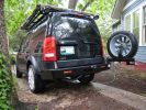
lr3-kaymar-open with 20"405 views
|
|

Thread upload1 viewsImage uploaded in thread 127470
|
|

Thread upload3 viewsImage uploaded in thread 127470
|
|

Thread upload2 viewsImage uploaded in thread 127470
|
|

Thread upload4 viewsImage uploaded in thread 127470
|
|
Thread upload3 viewsImage uploaded in thread 112864
|
|
Thread upload1 viewsImage uploaded in thread 112864
|
|

LR3-Wiring_exterior_lighting72 views
|
|

relocation of stuff to allow gigantic battery installation. The hood/bonnet barely closes wihout trouble.382 views
|
|
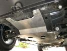
Rasta underbody protection plates448 views
|
|
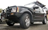
ARB bar and bfg tires430 views
|
|
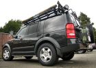
finally with more appropriate 18" BFG AT ko tires547 views
|
|

we put the fuses in the rear panel as well as the air tank gauge, air switch, and battery switch.417 views
|
|

avatar103 views
|
|

24 views
|
|
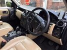
Thread upload13 viewsImage uploaded in new thread
|
|
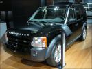
LR3 displayed prior to launch271 views
|
|

152 views
|
|

First Land143 views
|
|
141 views
|
|

Current Motor150 views08 Land Rover Discovery 3 TDV6 2.7L 5 Seater Base Spec
|
|

LR3 demo141 views
|
|

On a trail42 views
|
|

107 views
|
|

70 views
|
|
49 views
|
|

26 views
|
|
Thread upload11 viewsImage uploaded in thread 118635
|
|

Thread upload3 viewsImage uploaded in new thread
|
|

Thread upload5 viewsImage uploaded in thread 107148
|
|

Thread upload21 viewsImage uploaded in thread 112951
|
|

G4 Challenge90 viewsSpotted in Chelmsford Meadows Carpark 29th July
|
|

Thread upload7 viewsImage uploaded in thread 159778
|
|

25 views
|
|

Thread upload11 viewsImage uploaded in new thread
|
|

Thread upload3 viewsImage uploaded in new thread
|
|

Thread upload1 viewsImage uploaded in new thread
|
|

Thread upload5 viewsImage uploaded in new thread
|
|

8 views
|
|

Thread upload2 viewsImage uploaded in thread 5
|
|

Thread upload5 viewsImage uploaded in thread 147246
|
|

Thread upload2 viewsImage uploaded in new thread
|
|

Thread upload8 viewsImage uploaded in new thread
|
|

Thread upload2 viewsImage uploaded in new thread
|
|

Thread upload8 viewsImage uploaded in new thread
|
|

Thread upload1 viewsImage uploaded in thread 68618
|
|

Thread upload3 viewsImage uploaded in thread 180141
|
|

5 views
|
|

Thread upload2 viewsImage uploaded in thread 186441
|
|

Thread upload0 viewsImage uploaded in new thread
|
|

Thread upload0 viewsImage uploaded in thread 208886
|
|

Thread upload2 viewsImage uploaded in new thread
|
|
292 views
|
|
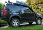
lifted with shortened "arms"289 views
|
|

275 views
|
|
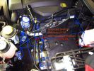
2nd battery fitting477 views
|
|
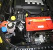
odyssey 2150 going in place467 views
|
|
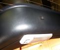
rear hatch light and door release switch390 viewswe\'ll ad a switch "guard" to protect from accidental gear shift popping button. light is slider 3 way so unlikely to be turned on by accident but will be nice down light when hatch is opened out.
|
|
a few items being built in behind cover panel.442 viewsred inverter will have fluch mount plugs, air outloet will be flush, guage with window in lower pop-panel and switches and fuses for all rear items behind popout panel.
12v sockets being added as well, high and low.
|
|
wiring progress423 viewslots torn out that somehow goes back together
|
|

solo steep gravel stop = park brake plus reverse on shifter333 viewsso our disco II\'s locked all 4 wheels with brake but now the modern lr3 slides away with only the park brake!!!! 1. put auto shifter in reverse (low gear) with foot on brake, 2. apply park brake, 3. get out and snap photo incase something fails and it slides away ;)
I reversed up the hill from this position, system decided to engage extended heigh mode for some reason trying to gain traction on loose surface.
|
|
sill up to my knees during extended mode.355 views
|
|
top of the hill338 views
|
|
293 views
|
|
284 views
|
|
153 views
|
|
120 views
|
|
118 views
|
|
Thread upload0 viewsImage uploaded in thread 5
|
|
Thread upload14 viewsImage uploaded in thread 1546
|
|

Thread upload0 viewsImage uploaded in new thread
|
|
Thread upload12 viewsImage uploaded in thread 1546
|
|

Thread upload4 viewsImage uploaded in thread 130551
|
|

Thread upload5 viewsImage uploaded in thread 130551
|
|
Thread upload19 viewsImage uploaded in new thread
|
|

fuel consumption43 views
|
|
Thread upload2 viewsImage uploaded in new thread
|
|
Thread upload8 viewsImage uploaded in thread 137017
|
|
Thread upload14 viewsImage uploaded in thread 1546
|
|

Thread upload3 viewsImage uploaded in thread 191038
|
|
Thread upload17 viewsImage uploaded in thread 1546
|
|
Thread upload1 viewsImage uploaded in thread 129636
|
|

Ashtray Slide6 viewsThis is a quick drawing describing how the ashtray stays in. There's a pin that rides through this channel, gets caught to stay closed, and pushing t in releases the catch.
|
|

Thread upload8 viewsImage uploaded in thread 142948
|
|
LAKs LR3527 views
|
|
Thread upload11 viewsImage uploaded in new thread
|
|
Thread upload2 viewsImage uploaded in new thread
|
|
Thread upload3 viewsImage uploaded in new thread
|
|
Thread upload3 viewsImage uploaded in new thread
|
|
Thread upload3 viewsImage uploaded in new thread
|
|

Thread upload4 viewsImage uploaded in new thread
|
|
Thread upload3 viewsImage uploaded in new thread
|
|
Thread upload3 viewsImage uploaded in new thread
|
|
Thread upload1 viewsImage uploaded in new thread
|
|
| 684 files on 2 page(s) |
 |
1 |  |
|