| Search results - "link" |

Put a link wire in these 2 holes (use a fairly thick wire ) - compressor will start ..you do not need the ignition on 926 views
|
|
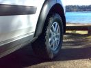
Rear / Standard Links / Standard Height233 views
|
|

Front / Standard Links / Standard Height.347 views
|
|

Clearance to top arm - approx 10mm. Standard Links / Standard Height.200 views
|
|

fuseable link 73 views
|
|
32 views
|
|

Avatar on the blink49 views
|
|

Tenuous link to Disco3!67 views
|
|
Thread upload11 viewsImage uploaded in new thread
|
|

14 views
|
|
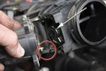
Removing the EGR Butterfly Valve Actuator1522 viewsRemove the 4 TORX screws to remove the actuator. The small black link (circled) connects the actuator drive arm with the butterfly valve spindle (arrowed). The spindle can now be very carefully levered out using a screwdriver inserted beneath the arrowed bit in the photo. A bit scary to do as it takes a fair bit of pressure before the spindle will free itself from the butterfly. Once it starts moving though, it gets easier to pull out.
|
|
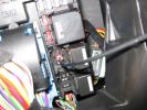
aux sockets relay - remove the relay and put in link wire 189 views
|
|
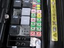
Fuseable link for rear windows 18e (50amp ) bottom right hand red square 135 views
|
|

9 views
|
|
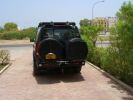
Rear end294 viewsLocally made wheel covers. LH is zipped from bottom to top to fit over registration plate with zip fasteners top and bottom. Rear IPF Reversing /camp lights on rack linked to reverse light circuit.
|
|
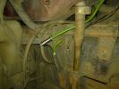
Cross link air pipe193 views
|
|
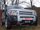
67 viewsHidden winch solution for D3 and D4.
Supplier: Taubenreuther in Germany.
Link: http://www.offroad24.de/shop/index.php?pli=1005055010&artnr=16-4950&view=detail
|
|
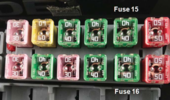
D3_link_fuse_14_and_1613 views
|
|

Blinky the D3 and the boys17 views
|
|

Thread upload0 viewsImage uploaded in thread 198243
|
|

Thread upload0 viewsImage uploaded in thread 198243
|
|

7 views
|
|
Thread upload8 viewsImage uploaded in new thread
|
|
Thread upload6 viewsImage uploaded in thread 134098
|
|
Thread upload8 viewsImage uploaded in thread 135945
|
|
Thread upload8 viewsImage uploaded in new thread
|
|
Thread upload8 viewsImage uploaded in thread 134098
|
|
Thread upload7 viewsImage uploaded in thread 135945
|
|
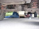
Rob removes Chris handbrake linkage after fire150 views
|
|
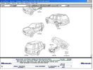
109 views
|
|

Gear Linkage22 views
|
|

Thread upload2 viewsImage uploaded in thread 198243
|
|

Thread upload2 viewsImage uploaded in thread 198243
|
|

Gore Tex Oleophobic Membrane Vents72 viewsThese is a link to a Gore website that explains how the Gore Tex material within the breather cap allow pressure to escape (but retains the oil) and allows moisture free air to come back in but excludes free water.
|
|

368 views
|
|
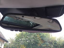
Homelink Rear View Mirror16 views
|
|
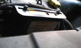
Solenoid not yet engaged12 viewsWith the engine running, the counter in the solenoid starts running and the green light blinks until the timer hits 5 minutes.
|
|

collecting wood27 viewslocals cant cut down trees (finally linked to landslides) so the wade into this fast flowwing river to collect drift wood. water is very fast flowing and muddy and has logs floating down
|
|
51 views
|
|
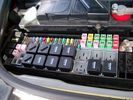
Picture of the engine compartment fuse panel5753 viewsEngine compartment fuse panel located near the battery. This is where F3E, (5 amp), F26E, (20 amp), Fuseable link 10E, (60 amp) and Relay 7E, the now upgraded 70 amp air compressor motor relay, part number YWB500220, (E is for Engine compartment fuse box), are all located. Fuse F35P, (5 amp), is inside the Passenger compartment behind the lower glove box door.
To keep the suspension from going down to the stops when driving, (or parked), it appears that it is only really necessary to remove F26E to depower the exhaust valve and generally keep all the valve block solenoid valves in a closed position trapping whatever air is within the air springs. F3E gets its power thru F26E, so when F26E is removed, the F3E circuit is automatically de-powered. F35P is more interesting in that battery power goes thru the ignition switch and F35P and then into the air suspension control unit. Apparently however, if F26E is removed, removing the F35P is not needed even when the engine is running.
With all fuses still in, if you have a problem, in practice, ideally, the compressor still works and will raise the 3 to an appropriate height. If so, one can then shut the engine off and allow the computers to go to sleep and then you remove the fuse(s). In actual practice, it seems that one need only pull the F26E fuse and can do so with the engine running. All the same, one might consider that the 3 is first a mobile computer, and secondly a 4x4. Computers prefer to go to sleep before the plug is pulled on them, however given that F26E circuit is always alive, then the computer never sleeps. With the fuse(s) pulled, and if you are still up, you can now be a 4x4 instead of a low rider. The whole purpose of the fuse pulling exercise is to depower the one and only system exhaust valve that is physically located within the compressor unit, (to keep it from opening), and secondarily to keep closed the four air spring solenoids within the block valves. This also shuts the air compressor down and stops the air compressor from making air even if the compressor is still good. That is why you initially need the fuse(s) in to allow the compressor to make air if it can.
|
|
Brand new blinking Discovery358 viewsDad is very happy with his new car, but mine daughter is more than proud and wil make a blinking picture. This is the first and only day to have a blinking Discoevery3.
Rene@LR3.nl
|
|
Blinking new Discovery3 just from the dealer, made by Sanne (10 years) , CALENDAR ENTRY 2009622 viewsHere the first picture from the brand new blining D3 made by sanne, 10 years old. CALENDAR ENTRY 2009
|
|
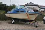
Slinky 313 viewsDolphin cabin cruiser and trailer
|
|
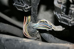
Cross-link valve broken wire115 views
|
|
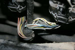
Cross-link valve broken wire106 views
|
|
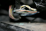
Cross-link valve broken wire97 views
|
|
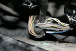
Cross-link valve broken wire98 views
|
|
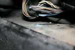
Cross-link valve broken wire105 viewsLeft front inner wheel arch
|
|
5 viewsD3 gearbox link
|
|
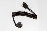
Genuine Discovery4 I-Pod Link Lead (LR031492)51 viewsGenuine Discovery4 I-Pod Link Lead (LR031492)
|
|
Weakest link, full screen is clear after 5 secs820 views
|
|

LED trailer lights adapter for LR3831 viewsThis doc includes a partial list of materials and the instructions/links required to construct an adapter to prevent LED trailer lights from pulsing due to the 3's diagnostic circuits interrogating the signal light circuit.
Using the adapter also facilitates the green flashing of the dash located trailer indicator when the signal lights operate plus inhibits operation of various systems such as the backup sensors, etc.
|
|

18 views
|
|
5 views
|
|

Thread upload1 viewsImage uploaded in thread 206434
|
|

57 views
|
|

Thread upload0 viewsImage uploaded in thread 206858
|
|

Thread upload0 viewsImage uploaded in thread 206858
|
|

Thread upload0 viewsImage uploaded in thread 174456
|
|

Vienna Green417 views
|
|
Thread upload1 viewsImage uploaded in thread 179272
|
|

Thread upload1 viewsImage uploaded in new thread
|
|

LR Electric Trailer Brake C2590 Female Connector599 viewsThis female connector, C2590, located up above and near the brake pedal is for the Trailer Electric Brake Controller hookup.
The Black wire in the bottom right is pin #3, the ground. The Blue wire to the left is pin #6, the Trailer Brake Controller output going to the rear trailer socket.
The White #4 wire is the 30 amp fusible link, (Link 6E in the engine compartment junction box), for the Brake Controller 12VDC power feed from the battery. Note that this would make a pretty good power source for CB radios and the like if no electric trailer brakes were required.
Pin #5 is a Green wire from the stop lamp switch, (the control input for the Brake Controller).
This plug is standard on all NAS (LR3) vehicles, but unlikely to be found on the D3 spec units.
|
|
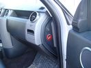
Air Suspension ECU Fuse 35P Shut Off Switch2623 viewsA more distant view of the shut off rocker switch in the ON position which is the normal position for when all is working as Land Rover intended.
Ideally, (but not totally necessary), the F35P circuit should be powered or de-energized after the various computers have gone to "sleep".
Similarly, removal of the F26E or F3E fuses is preferable after the computers have all gone to sleep but it appears that no real damage will be done if the fuses are removed while the system is energized. Pulling F26E is the main full time fuse that powers the air suspension computer. As such, once F26E is removed, pulling F3E is not really required.
Power for the compressor goes thru the 60 amp fusible link and relay, however control of the relay is via the air suspension computer so depowering the air suspension computer effectively depowers the air compressor and the internal exhaust valve relay/port.
|
|
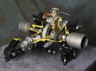
Rear Differential cutaway with E-Locker 1199 viewsThis jpg is from the link below.
There are another ten or so cutaways plus a whole file group showing a 2005 LR3 sectioned for the 2005 Chicago Auto show. Each jpg has an enlarge function to the bottom right of a main picture.
On one jpg you can see right into the stepper motor.
http://www.cutawaycreations.com/cutaways.php?project=land-rover-electronic-rear-differential#/IMAGES/car4/images/image1.jpg
Both the front and rear differentials are manufactured by Dana Spicer in the UK. Dana calls them a Clamshell design.
|
|

Underhood Fuse and Relay Box drawing 3041 viewsShows the various fuse and relay locations. Fuse 3E, (5 amp), and Fuse 26E, (20 amp), as well as upgraded 70 amp Relay 7, part number YWB500220, locations are displayed. Relay 7 sends battery power to the compressor from the 60 amp fusible link called up as 10E. Fuse 26E is what provides full time always on battery power to the air suspension ECU and hence powers the auto level wakeup when the vehicle is shut down and say parked for the night. Removing F26E is the primary method to disable the air suspension system; Removing F35P is more if you want to experiment with it from inside.
I found it useful when I had a suspension problem, (actually a wheel alignment problem picked up by the steering wheel angle sensor), that only showed itself on the highway but allowed for no trouble light driving in the city. This was because in the city, the steering wheel was always in motion and rarely was the vehicle driven in a near straight line for very much distance.
|
|

ARB link119 views
|
|

Thread upload0 viewsImage uploaded in thread 198910
|
|

Thread upload0 viewsImage uploaded in thread 198910
|
|

Homelink mirror connector21 views
|
|

340 views
|
|
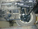
MGB GT V852 views5 Link rear suspension off-side.
|
|
Thread upload2 viewsImage uploaded in thread 144213
|
|
Sir Tiffy P G Pearce-Smith UK 201 viewsThe League of Venturers Search and Rescue is a charitable group from the UK that works with youth in the UK to give them rescue training, and life experiences. Read more or sponsor them at the link to their web site below.
They go on overseas expeditions, and practice daily breakdown training (grin). Spotted in Marble Falls Texas, USA.
http://www.vsar.org.uk/content/Activities/content/Overseas_Exhibitions.html
|
|
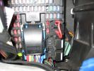
permenant aux sockets ..place link wire here 154 views
|
|

Pollen Filter Replacement in HVAC System500 viewsThe attached single page doc includes links to pictures of the procedure to replace the "air" filter behind the passenger side glove box related to the Heater AC system.
Part numbers are provided for both Land Rover and Mann filters, both the activated carbon type and the non charcoal filters.
|
|
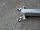
Hook links79 views
|
|
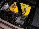
Installed and wired863 viewsShows the wiring loom to the isolator, the feeds (fused link) to the rear outlets and the other feeds are for the battery meter
|
|

slinky212 views
|
|
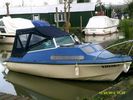
Slinky 211 views
|
|
![Filename=slinky2[1]~0.jpg
Filesize=82KB
Dimensions=800x600
Date added=25.Jun 2013 slinky2[1]~0.jpg](albums/userpics/28932/thumb_slinky2%5B1%5D~0.jpg)
Slinky 111 views17' Cabin Cruiser
|
|

Superinjunction85 viewsBefore Ryan Giggs was exposed as the two faced, nice as pie in public yet screwing any that moves behind closed doors hypocrite he is it was public knowledge that the woman in the story was some slapper from Big Brother but the footballer could not be named. Here we see TNT magazine's top story about her saying the footballer can't be named. Directly underneath is a link to a "related story" was a link to "Ryan Giggs, wife and kids celebrate Manchester United victory"
|
|

Toe link removal and installation124 views
|
|

Thread upload0 viewsImage uploaded in thread 207908
|
|

Disco on a sideways-slope134 viewsActually watching your own Disco tilted 30 degrees by a friend is not THAT funny... I got it so far that the back right wheel indicator in the 4x4-screen started blinking red. Pure adrenalin, won´t do it again though...
|
|

Thread upload10 viewsImage uploaded in thread 131610
|
|

Thread upload29 viewsImage uploaded in thread 108266
|
|

Thread upload25 viewsImage uploaded in thread 108266
|
|
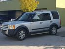
Thread upload10 viewsImage uploaded in thread 5
|
|

427 views
|
|

347 views
|
|
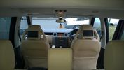
Screen's8 viewsScreen's linked to front DVD and rear PS2
|
|
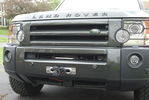
Hidden Winch Install10 viewsA front shot of my Front Runner Hidden Winch install with a Superwinch Talon 12.5 winch, D44 Hawse Fairlead, Factor 55 Flatlink Shackle, and Amsteel Blue synthetic line.
|
|
|
|
|
|
|