| Search results - "into" |
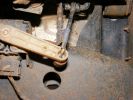
754 viewsNew control rod is carbonfibre/fibreglass hollow tube, with a rubber grommet fitted to one end (screwed and epoxy-ed) and steel rod bent into shape at the other (epoxy-ed).
|
|
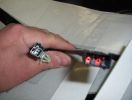
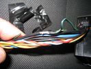
heated seat (base) wiring411 viewsThe Small connector takes the plug from the seat back pad, the larger connector (with red) is fitted into the multiplug casing uder the seat - the male side of this is already pre-wired.
|
|

And so it begins246 views
|
|
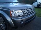
30 viewstransforming a discovery 3 into a 4.......
|
|
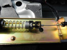
Cavo nel morsetto - Cable in clamp48 viewsHo inserito il terminale rotto nel morsetto: bisogna sforzarlo molto e ho praticato una cava attraverso il foro della vite con una punta in modo che il terminale non possa scivolare.
I entered the terminal broke into the clamp: you have to force it a lot, and I practiced a quarry through the screw hole with a bit so that the terminal can not slip.
|
|
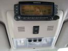
1 Dash SCREEN51 views
|
|
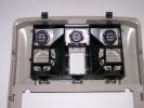
160 viewsThe switches fit into the new holes in the bracket
|
|
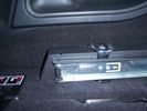
Close up of side runner, showing load hooks countersunk into runner .24 views50%
|
|
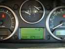
fuel range????????296 viewsfilled tank up and climbed the 21 hairpins into Alpe d\'Huez 1860m - as you can see the projected fuel range (due to the climb) suffered. The reality was different as it used virtually no fuel on the descent.
|
|

Decending into the clouds - 1860 going down187 views
|
|
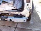
Bracket bolted into position257 views
|
|
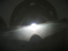
This is a H7R bulb fitted into the same headlight - look at cut off and no glare116 viewsPerfect like OEM what more can i say
|
|
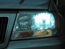
Standard hid bulb - light everywhere and glare caused by light in bottom of bowl96 viewsWhilst the beam pattern is ok the problm is that with 300% more light the spillage into the bottom of the reflector bowl is seen as glare by other motorists. it also is the reason the overhead motorway signs are lit up so well be bad retrofit xenons
|
|
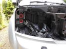
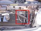
Remove Headlights and Grille using bulb replacement instructions in Manual - Push the fixings supplied into these holes circled in red152 views
|
|
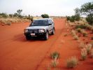
D3 in the Red Centre51 viewsOn the road into Rainbow Valley, on a cool desert morning in April.
|
|
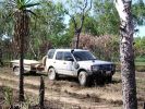
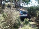
D3 in Kakadu National Park, on the track into the Alligator Billabong47 viewsThis whle area is down on the flood-plain, so in the Wet it is all under a few inches of water. In the dry it has a hard but brittle surface, which is then chewed up in many places by the feral animals with hard hoofs such as buffalo, pigs and horses. This then turns the track into a big dust bowl which is primarily bull-dust - a soft fine powder like talcum powder, which can be many feet deep, and gets into everything. The cover on the trailer is actually black.
|
|

Camp Draft - Winton QLD22 views
|
|

26 viewsFinally through the tube and into the car above the headlining
|
|
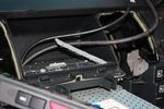
94 viewsCutting a trench in the dash pocket floor to wedge the bottom edge of the screen into
|
|
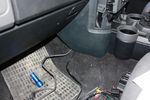
89 viewsCables out into passenger footwell
|
|

83 viewsReverse wire tapped into
|
|

78 viewsThrough the vents into the D-pillar
|
|

97 viewsOut at the C pillar. From here wires were threaded through the rear seatbelt anchor point into the commercial box, which is the hub of all the wiring and CarPC installation
|
|
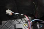
109 viewsThis is the plug for the accessory socket at the rear of the cubby box. On commercial D3 such as this one, there is no accessory socket so this plug is unused. I tapped into the 12V wire as an ignition feed. This will feed a relay coil which opens up power from the aux battery. Like this I can still retro fit and make use of the accessory socket later on.
|
|
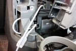
62 viewsCutout done, all that's left is to stuff the socket into the cutout
|
|
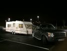
First foray into caravanning! 8 views
|
|
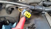
Test probe measure voltage18 viewsDo NOT insert the test probe into the connector as this can damage the terminal.
|
|
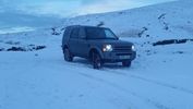
Gospel Pass Jan 2015146 viewsThe Gospel Pass (Welsh: Bwlch yr Efengyl) is the highest road pass in Wales. It is at the head of the Vale of Ewyas in the Black Mountains of southeast Wales.[1] The narrow mountain road climbs steeply from Hay-on-Wye to a height of 549 metres (1,801 ft) [2] above sea level, squeezing between the mountains of Twmpa to the west and Hay Bluff to the east, before dropping down into the valley to the south on its way to Llanthony Priory, Llanfihangel Crucorney and Abergavenny.
|
|

Steering Column detailing Steering Angle Sensor1496 viewsItem 2 in the picture on page 1 of the 9 page pdf shows the location of the steering wheel sensor. Page 5 of the pdf has a paragraph describing the operation of the sensor. When the steering wheel does not point the same direction as the real wheels, then the computers can put the 3 into safe mode and down goes the suspension. See also the 17 page pdf on the Anti Lock and Traction Control pdf.
|
|
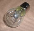
Land Rover Stop Tail Light dual filament bulb nominal 12 volt 21 / 5 watt filaments1427 viewsThis is the Land Rover part number 264590 dual filament bulb, (P21/5), that inserts into the upper two tail lamp receptacles. In the upper one, both filaments function, in the lower one, only the 5 watt tail light filament functions.
I regard it as not a good practice to routinely switch bulbs when the tail light filament, (5 watt), burns out on the lower bulb. The broken filament can jiggle over onto the brake light filament, (21 watt), and short the circuit to ground or something else not predicable.
There are also arguments to say that quality control is better on the Land Rover marketed bulbs than say far east sourced bulbs. Filament construction, and hence resistance can vary and mislead the current sensing circuits monitoring the signal light systems. Also when the bulbs are properly installed, all filaments should be standing vertically and not at any slope.
These are the sort of obscure circumstances that can lead to false trouble messages on the display, dropping to the stops, and subsequent concerns - all over a tail/signal light bulb.
For example, the filament life of both the tail light and the brake light filaments in the P21/5 bulb is significantly less than the USA common 1157 dual filament bulb, (1000/250 vs 5000/1200 hours); brightness in the P21/5 is a bit more, (3cp/35cp vs 3cp/32cp where cp is candle power), but current consumption is oddly less, (0.44a/1.86a vs 0.59a/2.10a where a is amps). It is the quest for efficiency vs maintenance trade off.
|
|
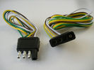
4 pin NAS flat connector from NAS small trailer382 viewsThe connector with the three exposed pins is the end that would commonly be located at the trailer hitch end, (front), of a small NAS lightweight trailer that has no electric brakes. This plug would connect into the flat 4 pin connector at the rear of the 3.
Note the order of the pin functions and wire colours: White is ground; the next pin is for tail/marker lights using the Brown wire; the Yellow conductor is for the left turn signal, and the far pin uses the Green conductor for the right turn signal.
There is no separate brake light conductor as NAS spec vehicles most often combine the brake and signal light functions to the same bulb filament rather separate filaments in different bulbs. The LR factory harness resolves that design difference.
Fortunately, the Land Rover NAS assembly pin order for the 4 pin flat plug maintains the above described conventions.
|
|
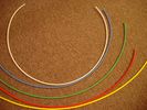
6mm Heat Shrink colours 362 viewsI decided to colour code the tubing so I used 6mm electrical heat shrink.
As there is no apparent colour coding re the 3, I tried to emulate the P38 coding; #1 LR red, #2 RR blue, #3 LF yellow, and #4 RF green. This was not doable as both left side air springs have green coloured tubing coming off the top of the front and rear air springs. I therefore arbitrarily chose the Left Rear to be red; Left Front green; Right Front yellow; Right Rear blue; and for the air compressor supply line, White coloured heat shrink. Since two new lines tie into each air spring line, I made the line between the air spring and the FASKIT, a single solid colour, and the line from the FASKIT to the valve block, White, plus the related appropriate solid colour.
|
|
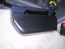
Ham Radio448 viewsThe remote head of an Icom IC706 was mounted on a piece of wood shaped to fit into the coin holder. This is quite a tight fit and does not shake loose. The radio is mounted under the driver seat.
|
|

Add A Circuit Littelfuse Data sheet2278 viewsThe switch connects to what Littelfuse brand calls an Add-A-Circuit model FMH200BP which is an adapter that plugs in place of a Mini fuse and then has space for two Mini fuses, (original and a second one). In this install, only the original 5 amp fuse was used - adapter was so as to route power from fuse box thru fuse, then rocker switch, and then back to fuse box.
Before you install the Add A Circuit for this application, take an ohm meter and trace out the circuit path of the four slots that fuses could insert into. The path is more complicated than one might first think. As such, the orientation of the fuse holder in the socket matters for this application - that is for a circuit diverter, rather than accessory adder.
|
|

Land Rover Aerial Fin images for both Glass and Metal Roof Disco3 / LR3864 viewsAs well as the two different fins, this pdf also shows the plastic blanking plate for glass roof vehicles where no fin is installed.
The glass roof fin is secured by two security screws from the top into a plastic frangible glue on gasket. The hope is that when struck, the fin will shear off and not crack the glass roof. Re the metal roof design, the fin is secured from underneath via two nuts.
The pdf also shows the various electrical bits related to the antennas. In the UK, the fin would house not only a cell phone antenna but the TV and satellite radio antenna electronics as well; in the States, the Sirius sat radio antenna and a G type cell phone antenna if the phone kit was installed would reside within the fin. The SAT NAV GPS antenna is located within the High Mount Brake Light plastic mounted to the upper rear hatch.
|
|

Alternator female plug looking down into top373 viewsThis shows the plug connected to the alternator wiring harness looking down into the top of the plug.
The cavity marked 1 is the AS or BATT SENSE and the wire colour most likely has Brown/Green on it.
The cavity marked 2 is the RC or ALT CON and the wire colour most likely has Red/White on it.
The cavity marked 3 is the L1 or ALT MON and the wire colour likely has Green/White on it.
I say "most likely" as the wire colours are not always the same on all vehicles.
Also the terminal 1 conductor destination is more likely C0570-175 rather than per the jpg.
The #3 pin is located closest to the big B+ terminal.
|
|
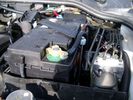
Aux Battery showing ground cable bolt "upside" down 1577 viewsIn order to obtain sufficient height clearance to get the plastic cover back on, I had to install the ground cable to the underside of the battery post connector.
Note the battery vent hose, (approx 5 ft required) is run down into where the windshield washer fluid container is located. There is not much electrical or metal in that area to be corroded by battery gas plus the open end of the vent hose tends to be protected from dirt and stays clean as well.
|
|
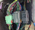
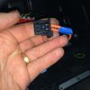
AUX wires?25 viewsIs this the AUX wires to tap into?
|
|
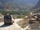
Bald Seet village164 viewsDescendign a steep concrete track over gravel into the villaeg of Ballad Seet. Curious in a dry, desert country to find verdent growth of palms, and agricultural produce on well watered terraces.
|
|

Bamford Bottom56 viewsBottom of the descent into Bamford
|
|

Bamford Top55 viewsStart of the decent into the lane at the top of Bamford
|
|

Thread upload3 viewsImage uploaded in thread 144213
|
|
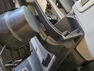
Bin Cover removed showing forward release clips that clip into the two rectangular slots.10 viewsOne has to pull up on the Bin Cover to unlatch the two metal clips, hence why release of the C pillar cover makes the bin cover removal and reinstall easier.
|
|
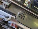
Buzzer located under black plastic cover.12 viewsThe white electrical connector clicks into the buzzer housing that is shown protruding from under the black plastic cover. There is a little tab on the white plastic that has to be squeezed to release the connector. In other words, do not pull on the two conductors.
|
|

LED light ON - looking into boot88 views
|
|

LED light OFF - looking into boot77 views
|
|
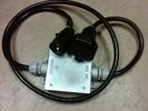
Box Closed with 7 Blade NAS connectors586 viewsBox closed up and ready for use. The box and cable connectors are reasonably weather tight and hence can be submerged for a bit while doing a creek crossing but as with the 3, do not use the creek bed as a parking stall. Similarly, the connector recessed into the bumper will probably remain somewhat dry as long as you keep moving but if you get stopped, well that is another story.
As such, I put a vial of desiccant in the metal box prior to closing it up to reduce corrosion due to moisture build up.
|
|

Brake Light Switch, Find, Remove, and Install Instructions 7853 viewsThis is a two page doc outlining where to find the brake light switch, how to remove it, and then install the new one.
Note, do not move the brake pedal when removing or installing the switch. Let the brake pedal hang where it wants to. The switch design is actually cunning, and as such is supposed to make the removal and install fool proof. Hence if you think too much about it, you can wreck the new switch.
If you want to inspect the interior of the switch, wait until you have removed the old switch. You can then just unsnap the blue from the white to get it apart. Inside, the switch is quite simple, (no circuit boards), but it will probably show black dust from failing contacts.
I think the reason the switch fails is that the Normally Open, (NO), contacts of the brake light contacts were made too light to carry the current load for make and break of the tail light filaments. I also think the black dust created then fouls the Normally Closed, (NC), second set of contacts for the ABS circuit. As such, the Normally Closed contacts become intermittent in operation and display as a fluctuating open and closed circuit condition to the ABS system when the ABS should be seeing a steady closed circuit. Hopefully the replacement switch contacts are more robust and may be as I recently replaced my switch again just as a matter of maintenance. While in a redesign, ideally the NC contacts should be sealed or at least separated from the NO contacts, when I inspected the removed switch, this time there was no black dust present.
Probably the removed switch will have a Land Rover oval logo moulded into it, the new one, FOMOCO.
|
|

Black Deposits on Brake Light Switch Plunger2758 viewsThis jpg I got off another forum and is typical of what one will see when one opens up the removed brake light switch. The black powder is residue from arcing of one of the pair of contacts within.
Hopefully the newer switches with the FOMOCO logo moulded into the plastic are improved from the Land Rover logo marked early units, however I doubt it.
The Ford part number is SW-6572 and/or 7E5Z-13480-A as used on the 2006 to 2009 Ford Fusion's and Mercury Milan's; the Land Rover part number is XKB500110. Cost of switch could be about twenty five dollars. A previous LR part number for the switch was XKB500030, so hopefully the newer LR part number, XKB500110, reflects some improvement in reliability.
It is possible that the new switches are better as I installed a replacement 72,000 km, (45,000 miles) later, at 195,000 km (121,000 miles). When I took the removed switch apart to inspect, it was clean inside. There was no black dust - the switch looked like new, hence they must be improved now.
|
|

Thread upload22 viewsImage uploaded in thread 92518
|
|

Thread upload26 viewsImage uploaded in thread 92518
|
|

100 views
|
|

83 views
|
|

90 views
|
|

81 views
|
|

79 views
|
|
Border crossing into Botswana from SA57 views
|
|

Thread upload3 viewsImage uploaded in new thread
|
|
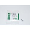
Clip Spring Metal FYC 500040 that holds LR together1747 viewsThe jpg is of the spring metal clip, Land Rover part number FYC 500040 that holds most of our 3 together - well at least most the interior trim parts.
If you are going to remove interior panels, you may as well stock up on a few for replacement as upon panel removal, the clips tend to spring away into deep never to be found voids within your 3.
|
|
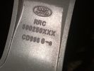
Part number moulded into spoke of 18" ten spoke. 322 viewsThis part number, RRC500250XXX is moulded into the backside of one of the spokes of the ten spoke 18" wheel. An alternate part number is ALY72190U or ALY72190U85 which relates to year and finish.
Another number is RRC500250MNH where MNH is also the finish, probably Sparkle Silver.
|
|

Finished - new seat base fitted back into D352 views
|
|

Thread upload1 viewsImage uploaded in thread 120453
|
|
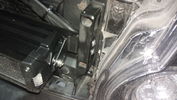
Lamp mounting details136 viewsTwo holes have to be drilled into the frame to fasten the brackets
|
|
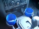
375 ml jam container372 viewsThese are the 375ml Danish Orchard brand jam containers. They fit fairly tightly into the original old style, (2005/6) Land Rover 3 factory cup holders. The extra height provided by the containers can be an advantage. I have a similar assortment of containers in some of the door panel located wine bottle holders to better hold containers of lesser valued products.
|
|
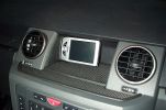
Mitac Mio 168 PDA403 viewsPDA with built in satellite reciever mounted into cradle mounted on "l" bracket to avoid drilling the side of recess.
|
|
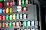
Tapa-Circuit Fuse Tap411 viewsTapa-circuit fuse tap fitted in existing fuseway provides extra fuseway which I have used to hard wire my Tomtom Sat Nav PDA. The fused output feeds into a female socket (Cigar lighter sized) into which the tomtom power adaptor is plugged. All hidden away behind the glove box.
|
|
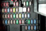
Tapa-circuit Fuse Tap435 viewsTapa-circuit fuse tap fitted in existing fuseway provides extra fuseway which I have used to hard wire my Tomtom Sat Nav PDA. The fused output feeds into a female socket (Cigar lighter sized) into which the tomtom power adaptor is plugged. All hidden away behind the glove box.
|
|
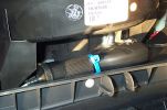
Hard wired tomtom498 viewsThe fused output from a tapa-circuit feeds into a female socket (Cigar lighter sized) into which the tomtom power adaptor is plugged. All hidden away behind the glove box.
|
|

Cooling System - Description and Operation 4.0L and 4.4L petrol engines 5 pages1028 viewsThis is a 5 page pdf that provides some insight into how the coolant flows thru all the hoses. Of interest is the paragraph,(page 3/5), that attempts to explain how and why the thermostat is designed to open at different engine operating temperatures - in brief, the reason for the spaghetti tangle of small hoses on the top of the engine.
There is also reference to an engine oil cooler that I gather cools something I think related to a supercharger, if fitted.
|
|

Ford at Great Alne - Warwickshire489 viewsGood long drive through here, a big drop into the start though and some deep water at the left on driving in, you can see me steer right to avoid!!
|
|

CALENDAR 2011402 viewsIn December 2009 we toured Botswana – first tour with the Disco, I had a yellow Defender previously. I rented a trailer, and the wheel bearing seized 1300km into the trip. This photo was taken while we waited for my friend to bring us a “fixed†hub. The elephant crossed the road less than 300 meters from us. Photo was taken 90Km from Nata
|
|
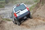
The decent into madness436 viewsDisco on its first day out, the 2nd day I owned it, access to quarry play ground is a little hairy, Ireland Event #8, calendar entry #1
|
|

59 views
|
|

51 views
|
|
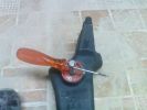
Put the screw driver into the hole then pull and turn to unlock160 views
|
|
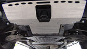
GOE Bash Plates119 viewsGreen Oval Experience Bash Plates. Front, Transmission and Compressor.
Might have to mod the front one a bit to let air into the trans cooler, it sits over the outside of the ARB bar which has vents for the cooler. If I cut slots in the Allow Plate to match those might do the trick.
I added a rear bolt to the Compressor Plate as it looked like it could get hooked on something and tear off. Two bolts onto the slider and two up onto the chassis now.
|
|
Picture of wire direct into headlight wiring181 views
|
|
Again just another pic of the wiring into the main175 views
|
|
Into ditch63 views
|
|
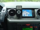
I-Pod installed into my Disco 3454 views I-pod video and Geosat2c installed. No visible damage to the deskboard, no holes etc.
|
|

Babu - great guy from Mozambique who joined Kingsley\'s core team.158 views"How the heck am I gonna fit all that in there?!"
Packing all the kit in Ondangwa. Amazing what you can get into a Defender!
|
|
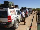
Crossing the bridge across the ruacana falls, just past the border post into Angola173 viewsWill - a chef of note, and a great companion. Kept us well fed, and well entertained
|
|
CALENDAR ENTRY - Christmas Eve at Calke Abbey497 viewsSlightly photoshopped to remove the colour in the background. Have the original if you prefer!
|
|
8 viewsWelded into a "replica race cat"
|
|
Smoked stripe on the windscreen442 views Installed 5 % foil into windscreen to hide the rear mirror tft lcd display a bit from the possible thiefs.
|
|
Dead engine135 viewsExhaust ports showing where leaked coolant has gone into the manifold and filled the turbo
|
|
Recovery hook113 viewsMakes it clear how the front recovery hook is mounted into the chassis
|
|
D3 Commercialisation622 viewsThis is the pic that was sent to me by the dealer to show what would be done to turn my SE into a van. (The car shown isnt mine)
|
|
211 viewsMike racing into pit 3 - as we were now both making it all the way through, the winner would be judged on time.
|
|
Installed winch electrical wires148 viewsWires which only power the solenoid are inside spiral wrap. They are also connected inside the wrap at the high point of the loop. Cable tied into place to prevent vibration rubbing.
|
|
Winch as installed177 viewsLicence plate is held on by winch cable and 4 metal pins which fit into modified bumper body. Winch rope is green
|
|
498 viewsRear iPod cabling solution. Notice the hole where the cables descend into the rear of the center console.
|
|
Neo heading into the axle-twister166 views
|
|
Gatcombe Park, 09/06 - Dropping into the stream156 views
|
|
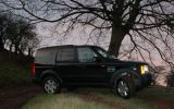
Off Roading in Wales506 viewsTrip into wales borders - church stretton green lane
|
|
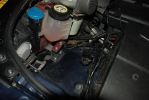
144 viewsbracket installed into existing mounting holes for coolant reservoir
|
|
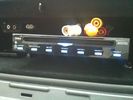
DVD Player63 viewsVeba DVD Player fitted into top glove box, AUX in for connection of Ipod, Games COnsoles etc. Remote control with sensor mounted by rear view mirror.
|
|
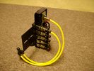
FASKIT on end view 864 viewsEnd and rear view of the FASKIT. Yellow lines are as shipped for hooking to the air supply; one line to valve/filler and other is to gauge. I will modify the arrangement to delete one of the yellow lines such that gauge line plugs into where the second yellow line is right now,(will be only one yellow tube), and then the air source line will plug into the port controlled by the valve, (hidden in this view but visible in other view). When white valve is in the ON position, gauge will read air source pressure, and be available to supply air to any of the selected four air springs. When valve is closed, the gauge will show individual air pressure in each of the air springs when a jumper is run between the gauge Schrader valve and the appropriate air spring Schrader valve.
|
|
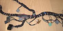
Finished Passenger Kick panel area131 viewsMissing connetor (left most grey) & wiring in, (plastic bracket was broke will use the one in the car) Airbag wires & connector to connector previously cut replaced (on top of grey one to right).
And you can even see the 2 new speaker wires going into the Pass door connector at the very bottom.
|
|
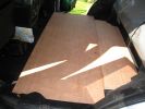
Front-section sloteed into rear to form a nice even floor147 views
|
|

Fluid, Filter/Pan Combo removal and install5980 viewsThese are the LR instructions re removal and install of the plastic pan/filter combo for the ZF 6HP26X transmission on the 4.4L petrol V8 LR3.
The instructions tend to ignore the reason you have to lift the right hand side of the engine about 40 mm. This is because of a frame cross member that interferes with dropping down of the plastic pan. The real problem is a vertical "oil filter spout" that rises out of the filter/pan combo up into the transmission. The spout is the suction pipe for filtered transmission oil back up into the tranny.
On the metal pan versions, the filter is separate from the pan, hence the filter remains with the tranny when the metal pan is dropped. The filter is then removed or installed independent of the metal pan, hence with the metal pan, there is no need to lift the engine.
If one is removing the plastic pan so as to install the metal pan, then some do not lift the engine but just drop the plastic pan enough to gain access to saw off the vertical plastic spout - it is a one time procedure.
Be aware however that the metal pan uses a flat gasket and the plastic pan uses a O ring like perimeter gasket that sits in a half round groove in the tranny casing. Also the metal pan uses 21 shorter torx M6x22.5 metric cap screws for the perimeter bolts. The plastic pan uses longer M6x28.5 torx metric cap screws.
|
|
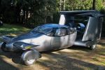
Is it a Car? is it a Plane?108 viewsA new car could prove the perfect way to beat rush hour traffic - because at the flick of a switch it turns into a plane. The AirCar will be able to cruise at speeds of 200mph - at a staggering 25,000 ft. It will cost around £250,000 and should be on sale by 2010
|
|
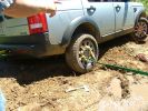
Furrow122 viewsThe rear tyre has descended into the furrow and the vehicle is now safer at last.
|
|
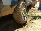
Rear wheel dig116 viewsYou can see here how much the right rear tyre has descended into the furrow we dug.
|
|

Fix stiff gear selector or jumping out of drive into neutral32 viewsThis is a document culled from a topic about a simple fix to teh gearbox selector lever that fixes a problem with jumping out of drive into neutral.
I made the document to give to my local independent and thought it might be useful for others.
Thanks to disco_mikey, EdF and Robbie from the original post whose information and photos made this possible (I take no credit for anything here apart from errors).
|
|

Fix stiff gear selector or jumping out of drive into neutral17 viewsUpdated 19 Dec 2012
This is a document culled from a topic about a simple fix to the gearbox selector lever that fixes a problem with jumping out of drive into neutral.
I made the document to give to my local independent and thought it might be useful for others.
Thanks to disco_mikey, EdF and Robbie from the original post whose information and photos made this possible (I take no credit for anything here apart from errors).
Updated after I did this fix on my own car.
|
|
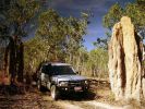
D3 in Kakadu National Park, on the track into Graveside Gorge51 viewsKakadu National Park is in a World Heritage area, with the entrance about 3 hours out of Darwin. It took another hour to get to the un-marked track into Graveside Gorge, which then took three hours to travel the 41km in. Not a tough track, but a series of big wash-outs with very deep and soft sand in the creek beds made driving fun. The most amazing thing, was that we had the whole place to ourselves. No marked tracks, so bushwalking involved blazing a trail using GPS and topo maps to find the way.
|
|
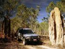
Calendar 2010 - D3 at Kakadu National Park283 viewsCalender 2010. D3 on the track into Graveside Gorge, Kakadu National Park.
|
|
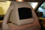
Headrests64 viewsNew screens built into headrests
|
|
Earth or -Ve connection required under Driver Seat. Cut the green and black and splice into the blac.134 views
|
|

Thread upload12 viewsImage uploaded in thread 136537
|
|
Bulgaria - HighestPointOnTheTrail20 views
|
|

Bulgaria - HighestPointOnTheTrailSmall21 views
|
|
Last leg into Inverness, via Aviemore (glow in the distance ) .. Starting to flag !140 views
|
|

iPod aux connection15 viewsPictures of installation of iPod into d3 cd player
|
|

collecting wood30 viewslocals cant cut down trees (finally linked to landslides) so the wade into this fast flowwing river to collect drift wood. water is very fast flowing and muddy and has logs floating down
|
|
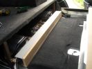
1492 viewsComputer and sub bass mounting board pusshed back into place
|
|
Picture of the engine compartment fuse panel5780 viewsEngine compartment fuse panel located near the battery. This is where F3E, (5 amp), F26E, (20 amp), Fuseable link 10E, (60 amp) and Relay 7E, the now upgraded 70 amp air compressor motor relay, part number YWB500220, (E is for Engine compartment fuse box), are all located. Fuse F35P, (5 amp), is inside the Passenger compartment behind the lower glove box door.
To keep the suspension from going down to the stops when driving, (or parked), it appears that it is only really necessary to remove F26E to depower the exhaust valve and generally keep all the valve block solenoid valves in a closed position trapping whatever air is within the air springs. F3E gets its power thru F26E, so when F26E is removed, the F3E circuit is automatically de-powered. F35P is more interesting in that battery power goes thru the ignition switch and F35P and then into the air suspension control unit. Apparently however, if F26E is removed, removing the F35P is not needed even when the engine is running.
With all fuses still in, if you have a problem, in practice, ideally, the compressor still works and will raise the 3 to an appropriate height. If so, one can then shut the engine off and allow the computers to go to sleep and then you remove the fuse(s). In actual practice, it seems that one need only pull the F26E fuse and can do so with the engine running. All the same, one might consider that the 3 is first a mobile computer, and secondly a 4x4. Computers prefer to go to sleep before the plug is pulled on them, however given that F26E circuit is always alive, then the computer never sleeps. With the fuse(s) pulled, and if you are still up, you can now be a 4x4 instead of a low rider. The whole purpose of the fuse pulling exercise is to depower the one and only system exhaust valve that is physically located within the compressor unit, (to keep it from opening), and secondarily to keep closed the four air spring solenoids within the block valves. This also shuts the air compressor down and stops the air compressor from making air even if the compressor is still good. That is why you initially need the fuse(s) in to allow the compressor to make air if it can.
|
|

Switch is blue colour thing thru the rectangular opening.3177 viewsThe blue coloured plastic bit thru the rectangular opening is the brake light switch. The fist time, I found it easier remove the switch by dropping the horizontal plastic panel, (two screws), and then slipping my hand in and rotating the switch clockwise 1/4 turn. The second time, I was able to remove the switch thru the rectangular opening and did not need to remove the horizontal lower panel. Obviously, I had to remove the sloping knee pad panel, (note sort of hinged at the bottom so pull back from the top.)
Regardless, do not touch the brake pedal - just let it sit where it wants to. One has to first remove the angled knee pad panel that sits under the steering wheel. It can be pulled from the top corner at the door side. Pulling releases a pair of those U shaped metal clips that LR loves so dearly. You have to pull quite hard. The bottom is held by a couple of plastic fingers in a couple of slots so you pull at the top till the two clips release and then rotate the panel and pull upwards a bit.
To remove the switch, you rotate it clockwise and pull outwards. Rotating the switch clockwise automatically retracts the plunger back into the switch body away from the brake pedal arm.
Similarly when you install the new switch, the required 1/4 turn anti clockwise rotation action releases the plunger so it lays up against the brake pedal arm and at the same time, secures the switch in place.
To remove the electrical wires, the switch will drop below the horizontal pad and hang from the wires so unclipping the electrical connector plug is fairly easy to do.
|
|

Camping trailer going into store38 views
|
|

drilling holes into cubby box for AV connection panel54 viewswork in progress
|
|
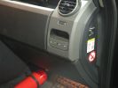
463 viewsFirst step in the journey, installed USB ports.
At the time I installed these, the goal was to use them in combination with the car-computer that resided in the back.
In the meanwhile, I dismantled the car-computer and nearly everything that was connected to it (touchscreen front, Wifi, DVB-T ...).
I kept the USB outlets in the front and turned them into charger for the appliances missus brings with her when we're on holiday. Mainly her iPod and smartphone ...
|
|
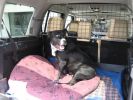
One happy customer - Artù322 viewsYes, whilst I was fitting everything, he was going mad as he loves to be in the car. He\'s actually had a failed entry into the Disco as it\'s too high for him!!
|
|
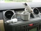
Full setup...563 viewsThis is a side view of that setup. As you can see, all the wiring can be hidden from view in the bottom of the car adapter (The part that goes into the cup holder...)
|
|

led boot space light upgrade96 viewsClose up showing how easy the led ultra bright modules fits into original housing
|
|
Day Light Driving lights211 viewsFit the lights into the holes cut and then secure. Left hand side.
|
|
208 views1st venture into the brown stuff, 36 hours after collecting her, all working fine...
|
|
391 viewsDisco3 - into the woods
(photo by Kai Uwe Richter)
|
|

Rosen DVD69 viewsMy overhead rosen dvd player with sony playstation 2 into aux.
|
|
Outside Winton, QLD, Australia163 views
|
|

VMS & HiICE integration81 viewsIntegration of VMS AVNC navigation system into D3 dash with HiICE stereo.
|
|

Dribbling into footwell here from closed door23 views
|
|

FFRR SC Grill into D3 Frame180 views
|
|
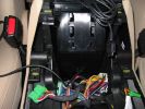
This is the hole that I drilled to get the iPod cable into the center storage area.467 viewsThe hole needed to be this large as both ends of the cable are large.
|
|
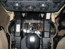
Here\'s a view of the Drive+Play "brain" which I mounted in the empty space in front of the gear selector.650 viewsI ran the power and audio cables to the rear of the center console in order to tap into the 12 volt power and "Aux" adapter. When you're sitting in the back seat, you don't see any cables whatsoever. My entire goal was to make it look as factory original as possible.
|
|

LED light - cable through boot into upper tailgate104 views
|
|
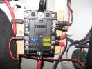
LED light - wired into power board114 views
|
|
Img 684 viewsBefore fitting the lights into the car. Grind down the small ridge. This insures for a better fitting.
|
|

Elephant at Etosha166 viewsI didn\'t have the guts to try get the D3 into the shot!
|
|

The good stuff going into the oil cooler11 views
|
|

Looking across the Cunene river into Namibia. The dunes are in the Skeleton Coast National Park, Namibia162 viewsPicture taken by Paulo Fernandes
|
|
MOST Connector16 viewsThis connector plugs into the back of the Screen (TSD)
|
|
View of tailgate actuator with cable going into it98 views
|
|

internet into house21 viewsinternet into house is small dish on top
|
|

Thread upload6 viewsImage uploaded in thread 194430
|
|

Thread upload3 viewsImage uploaded in thread 194430
|
|

Replacement switch from RRS installed on LR3864 viewsThe switch shown is LR part number YUZ500020, the upper rear hatch release switch that is found on the Range Rover Sport.
The switch body is the same switch as on the LR3 except that there is no wiring disconnect on the LR3. Hence when the switch corrodes and requires replacement, the LR solution is to purchase a new handle and license plate light assembly. I instead cut off the old switch and installed a JAE mating connector to the existing wiring and hence just plugged the RRS switch in.
The replacement RRS switch snaps into the same rectangular space in the same manner as the removed LR3 switch, the difference is the JAE male wiring connector.
|
|
Cruiser vs. Rover386 views Land Cruiser placed 2nd into my selection list
|
|

Harness that connects inside left rear compartment.445 viewsThis is the harness section that connects behind the left rear interior access panel and exits thru the large grommeted hole to below/behind the left rear tail light.
Note the two rubber grommets on the harness as there is both an interior metal skin and an exterior metal skin behind the left tail light assembly.
The two light grey connectors plug into two existing connectors near the top of the rear left interior access panel. The two darker connectors plug into the second piece of harness.
There is no little separate fuse box either with the NAS spec harness. The fuse box is included with the UK 13 pin dual plug units. If there was a fuse box, it would be on this portion of the harness.
|
|

Littelfuse Add-A-Circuit MINI and ATO style data sheet150 viewsPDF from Littelfuse showing both the MINI and ATO style of fuse holders. The 3 uses the MINI size of fuse. The MINI Add-A-Circuit can be inserted in place of one of the existing fuse panel MINI fuses. The removed fuse is then inserted into the lower slot of the Add-A-Circuit and a second fuse in the second slot to protect the device that you are adding. The Add-A-Circuit is designed for a max of 10 amps on the second load, and I guess maybe the original circuit as well.
|
|
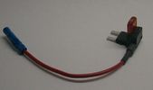
Littelfuse Mini Add-A-Circuit FMH200BP and OFH0200ZP1622 viewsFound this jpg somewhere on the forum - others are using them as it is a good way to tap the fuse box to add a fused circuit, or in this case, to modify a circuit to add a switch such that the fused circuit is switched. In my SmoothTalker gallery, there is a PDF from Littelfuse specifically related to this Add-A-Circuit device.
Before you install the Add A Circuit for any application, take an ohm meter and trace out the circuit path of the two pair of slots that fuses could insert into. The path is more complicated than one might first think. As such, the orientation of the fuse holder in the socket may matter depending upon the application. If the application is a circuit diverter, (as the F35 mode is), as opposed to a mere accessory adder, orientation matters.
|
|
388 viewsCompleted Install of Control Panel. Wiring goes up into headliner, over curtain airbag on left hand side, and down the B pillar.
|
|
Battery Maintainer switch box and connector 723 viewsThe Hammond box contains a DPDT toggle switch with centre off. The Positive and Negative from each battery feeds to the switch. Depending on the setting of the toggle, (full left, full right,or centre off),the respective batteries connect into the pigtail that can stick out thru the grill when one wishes to connect the charger.
This allows one to charge each battery independently via a suitable battery maintainer. I use a CTEK unit that feeds a maximum of 3.3 amps at 14.4 or 14.7 VDC, depending upon setting. The wiring therefore allows for a slow recharge of either of the batteries separately if either one requires such.
|
|
Empty space in NAS LR3 for location of FASKIT panel599 viewsThe empty space is available as the North America Spec gasoline engine LR3's do not have the Fuel Burning Heater installed. The air lines from the four air springs and the air tank will appear to rise up from under the headlight assembly. The lines to the front block valve assembly located behind the front right fog light will sort of run within the bumper across the front of the radiator down into behind the righthand fog light. The rear lines somewhat follow the path of the existing air feed line from the front valve assembly to compressor. Rather than be located between the left front fender liner and left metal wing however, the four lines will feed thru the empty wing space inside and above the wheel well arch and exit down by the left front mud flap. From there, the lines run along the left frame member above the air tank and then parallel the frame over top the compressor to the top of the rear left air spring where the rear air block valve assembly is located.
|
|

NAS 7 Blade Round plus NAS 4 Pin Flat Vehicle end Socket528 viewsThis shows the function of each blade when looking into the connector at the vehicle end for the 7 pin NAS plug. The layout is the pin order for most new North American pickup trucks and the LR3/4.
The colour and gauge of the wires feeding into the back of the plug varies even within manufacturer model lines.
Also detailed is the flat 4 pin layout common on smaller trailers not having electric brakes. This includes most U-Haul rental trailers.
|
|

NAS 7 Pin Round Socket + 4 Pin Flat Socket oriented as installed.752 viewsThis is the layout you see when you look into the NAS Land Rover sockets as installed at the rear of the LR3/4. The flat 4 pin socket is located under the round socket.
Wiring order is relative to the slot on the round socket, and hence the same as the other jpg where the slot is shown at the top.
The CJB monitors the front and rear turn signal lamps and can detect if more than four lamps are fitted, (the side turn signal lamps are not monitored). This is another reason for using genuine LR bulbs as off shore bulbs can have varied and out of spec resistance values.
When a trailer is detected, the trailer warning indicator in the instrument cluster is supposed to flash green in synchronization with the turn signal indicators.
If one or more of the turn signal lamps on the vehicle or the trailer are defective, the trailer warning indicator will cease to flash any longer. This is to alert the driver to probably bulb failure.
If the trailer has LED lamps installed, and no LED adapter circuitry is used, most likely the trailer will not be sensed and systems such as the backup sensors will not be disabled.
|
|
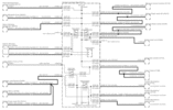
Power Window Circuit centered on Central Junction Box (behind glove box fuse panel)733 viewsRelay 143, the power window relay, and most other relays and FET's as well are built into the back of the passenger side behind the lower glove box fuse panel.
As such, the relays etc are not removable, jump-able, or serviceable.
|
|
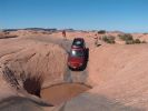
Into the Bath Tub on Hell\'s Revenge377 views
|
|
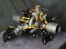
Rear Differential cutaway with E-Locker 1210 viewsThis jpg is from the link below.
There are another ten or so cutaways plus a whole file group showing a 2005 LR3 sectioned for the 2005 Chicago Auto show. Each jpg has an enlarge function to the bottom right of a main picture.
On one jpg you can see right into the stepper motor.
http://www.cutawaycreations.com/cutaways.php?project=land-rover-electronic-rear-differential#/IMAGES/car4/images/image1.jpg
Both the front and rear differentials are manufactured by Dana Spicer in the UK. Dana calls them a Clamshell design.
|
|
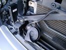
Wire (tubing) loom on right to down into bumper 465 viewsThis shows the 19mm loom in the trough between the bumper and the rad as it drops down into the right fog light area.
|
|
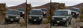
Smooth off road ride!399 viewsThis was the first time I took my LR3 off-road. I traded my Jeep Wrangler for this vehicle so I was used to heading into the rugged mountains. I was very amazed (as were my friends in their Jeeps) just how level the LR3 remained as I navigated over various dips and mounds. You can see the Cherokee behind me couldn't say the same.
|
|

LR3 Denso Alternator YLE500390 pulley view819 viewsNote the DENSO sticker on the side. Denso calls their nominal 150 amp 12 Volt alternator an SC2 design. SC means Segment Conductor which apparently increase the winding density of the stator coil, hence yielding a physically smaller lighter alternator for a given output. I presume the 2 means the second try at getting it right. A Denso part number is 4280003690 for the alternator, (there are others, as below).
Rotation is clockwise and the 54mm diameter pulley has 6 grooves (PV6x54). Count the pulley grooves on both the one you remove and your new one - some replacement alternators seem to ship with 5 or 7 grooves so you might be swapping pulleys.
A previous LR part number was YLE500190 for the older variation of the newer YLE500390 unit.
An additional part number for a factory rebuilt is Nippon Denso 210-0569 for the petrol V8 alternator. Other Nippon Denso numbers include 104210-3690 and 104210-3691. The Lester number is 11206 which relates to another Denso number of 290-5287. WAI uses 11206N.
From 2006 to 2009, the internal regulator is a Transpo IN6349 and of the B circuit type if it can be said that applies to PWM, (Pulse Width Modulated), regulators.
The "regulator" inside the alternator is therefore really not a regulator in the old sense of the term but instead an instruction receiver from the ECM that translates Pulse Width Modulated (PWM) signals into a form that the alternator understands – digital like signals from the Engine Control Module(ECM) into analogue like signals that the windings understand.
|
|

Land Rover Brake Light switch XKB5001102700 viewsThis is what the switch looks like when removed from the parts box. Note that the plunger is recessed back into the body and when installing, the process of rotating the switch body 1/4 turn anticlockwise releases the plunger so it pops longer and engages the brake pedal. If you look down on the plunger you can see curved slots where the rotation takes place.
Do not try to rotate the new one - play with the one you remove. Also do not press on the brake pedal when removing or installing as you will damage the plunger - this is one of the reasons the plunger is retracted into the body for installation. It is also for this reason that if you try to confirm the operation of the switch contacts with an ohm meter by pressing the plunger, the switch will appear not to function as one might anticipate. Have faith, the switch will however, once installed and the plunger is in full motion.
|
|

Horn Wiring Circuit LR3578 viewsThe is the wiring diagram for the dual horn circuit.
The Horn Relay, (R133), is not a big black thing hidden somewhere but instead what is called a FET, (and it is hidden)!
This is a Field Effect Transistor that is built into the circuit board that is mounted to the back of the fuse box that is located behind the lower glove box door on the passenger side of the 3. The related 15 amp fuse, 12P, is mounted in this fuse box and is often called F12P, where F is for fuse, and P is for Passenger compartment.
This is to help differentiate from another fuse and relay box, (the usual kind), that is located beside the starting battery in the Engine compartment. FxxE is often used in the naming of those fuses.
|
|
![Filename=LR3_Radio_Removal[1].pdf
Filesize=190KB
Dimensions=320x240
Date added=04.Feb 2014 LR3_Radio_Removal[1].pdf](images/thumb_pdf.jpg)
Radio Removal from Radio Stack571 viewsThis shows how to remove the radio from the stack. Basically you remove the H surround first and then at least loosen all the Torx 20 screws left and right sides from the top down starting at the narrow unit that the four way flasher/locking buttons are mounted on.
The units kind of interlock, hence some movement of each is required to remove the radio by itself. I find it best to take out the four way flasher/locking buttons assembly first as that allows access to the fibre optic cable connector into the back of the radio head without too much tugging.
|
|

Stop Light Lamp Circuit pdf2491 viewsThis pdf shows the brake light circuit for the NAS LR3.
Note that power for the brake light bulbs can come either thru the brake light switch power feed /contacts plus also from the Hill Decent Control, (HDC), system relay located within the Central Junction Box, (CJB) - yes two separate sources of power for the brake light bulbs. This would tend to explain how a brake light circuit concern shows up as a hill decent fault message; also why lesser vehicles without hill decent braking mechanisms, (HDC), never display this sort problem when a brake light bulb or switch acts up. You never have a problem related to a system that does not exist.
Additional evidence of the relationship of the HDC and the tail light circuit is demonstrated by when the HDC actually acts to slow the 3 down, the brake lights automatically illuminate even if the slowing action was merely retarding the engine speed or shifting to a lower gear, (in other words, no foot on the brake pedal).
There is also a tie in to the Cruise Control and hence a failing brake light switch can affect cruise operation or just create false Cruise Control messages. To further complicate the issue, while there are no messages generated, operation of the radiator electro viscous fan can also be negatively affected by the fouled set of secondary contacts within the brake light switch. This is all because the NC contacts within the brake switch send misleading messages to the ECU.
While the ground wire design is similar to other vehicles, note the grounds for the brake light filament and the reverse light filament are common on each side. That means that if one has a non functioning brake light on one side, the reverse light may not also work or that some problem with the reverse lights could back feed into the brake lights. This situation while unusual, can result when grounds are corroded probably due to swimming in rivers and creeks or just routine driving in a marine environment.
|
|

LTB00218 - Technical Bulletin - Water Leak into Footwell From Roof Opening Panel Drain Tube97 views
|
|

Way Finder Overlay Exporter example imported into Memory Map324 views
|
|

Nice Doggie Mr Clinton175 views
|
|
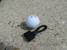
MOST fiber optic loop tool469 viewsThe looping tool in the jpg uses the Land Rover type plastic fiber optic cable with both ends feeding back into a female fiber optic connector that mates with the male fiber optic connectors on the Land Rover system.
The purpose of the loop is to allow one to disconnect MOST connected items such the BlueTooth module or the HK amplifier but allow the MOST system to still transmit signal from the head unit as the circuit would remain closed and hence complete. Of course with the Bluetooth module disconnected, there would be no Bluetooth available, however the radio and NAV would still function.
The looping tool allows one to troubleshoot the system by removing one component at at time from the MOST loop. In other words, what might appear to be a radio problem could be a Bluetooth problem - that sort of thing.
|
|

Mt Tamborine - panorama181 viewsPhotos taken on run into northern New South Wales - Hang gliders launch from here. Compiled from 5 images stitched with AutoStitch, a freeware application in development - superb application that requires little input other than reasonably good images.
|
|

94 viewsThe road turned into a trail at this point. A very muddy trail.
|
|

Thread upload1 viewsImage uploaded in thread 204017
|
|
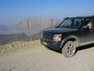
Day trip into the Wsetern Hajar mountains and wadis in Oman145 viewsSeries of pics taken en route - 80km all told and from sea level to 2300 metres above sea level.
|
|
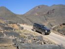
Over the hill to Balad Seet166 viewsAfter some 50km along dry river beds (wadis) and a climb of some 1500 metres in 3km you descend a gravel road into this charming mountain village.
|
|
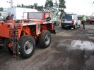
50t capacity trailer for D3 !!!80 viewsD3 comes in handy for splitting away 2 axles of a larger modular hydraulic heavy haulage trailer, just delivered an 80t transformer for me into Scotland, and we shortened the trailer for the journey back to Italy.
|
|

90 tonnes Transformer - Tooley Street84 viewsOur 300t Lift System with a 90 tonnes transformer hanging from it just before lowering 9 metres into a basement.
|
|
firewall plug run933 viewsThis is the engine side view, of where to poke the hole with a screwdriver to make a hole into the vehicle. You can barely see the edge of the hole. Note: The Rubber plug should be removed for this operation.
|
|
inside bumper view of lever476 viewsView into the bumper of the free spool lever.
|
|
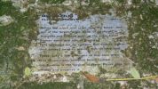
Plaque near Rocky Creek Dam129 viewsPlaque honouring Big Scrub Flora Reserve. A few kilometres along on Gibbergunyah Range Road that goes up to headwaters of creeks flowing into Rocky Creek Dam.
This reserve was part of one of the largest single tracts of rainforest in Australia.
|
|
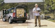
How many cases can you fit into a D3/LR3?228 viewsCurrent advert in Australian print media shows 30 cases packed in!
|
|
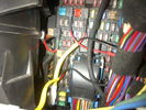
Fuse Panel showing F35P Add A Circuit installed1241 viewsFive amp fuse F35P is located towards the top left in this jpg. The other three Add A Circuit devices are for other items - powering my cell phone base etc.
Note the orientation of the Add A Circuit as this matters. Also one can just see a red tab sticking out from behind the device. The red is the conductor crimp end of a narrow 2.8mm male spade type connector that inserts into one of the "fuse" slots.
|
|
71 viewsRear cover off, slot dremeled into cover. I also had to cut off the entire bottom edge off the cover at a later stage for it to fit comfortably in the dash pocket.
|
|

parked or abandoned 15 viewsOnly just about fitted into this spot........
|
|
Astons disappearing into the night (should have taken the pix earlier)156 views
|
|
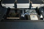
725 viewsMcintosh and Alpine amps. Crossovers for speakers
|
|
216 viewsThe start. I plan to place all the electronics into the lower glove box.
|
|
278 viewsA mess of cables. You can see the HD Radio antenna adapter coming out into the slot for the IHU. You can also see, if you look very closely, the original diversity antenna connector plugged into another adapter to go down to the HD radio unit.
|
|
329 viewsInstallation slowly proceeding. You can see the controller cables inserted into the notch I made with a dremel.
|
|
Thread upload19 viewsImage uploaded in thread 174038
|
|

Transpo Regulator IN6349 Pin Assignment716 viewsThis pdf shows the Land Rover and Ford pin naming for the 3 pins in the receptacle of the Transpo IN6349 regulator that accepts PWM signals. This jpg is as if you are looking into the receptacle located on the alternator.
Also provided are the Transpo pin names that are in common use and that some may be more familiar with plus some comments re testing.
The IN6349 regulator is used in the newer LR part # YLE500390 alternator. For the older YLE500190 alternator, the regulator is a Regitar VRH2005-142 unit that is shaped a bit different than the newer IN6349 regulator. Externally, the main difference is that no shiny fins are visible on the rear of the newer YLE500390 alternator. The pin naming and numbering is the same for both and both alternators are interchangeable.
|
|
Reservoir Air In fitting installed 1661 viewsSchrader valve installed. Shop air can now be introduced into the tank to facilitate the raising of the 3 when there has just been a failure of the onboard air compressor rather than the electronics or valve block wiring etc.
Air could also be sourced from this point, however the purpose of the modification is air in, not air out as the air pressure normally runs above 200 psig, too high to be safe for routine use unless a pressure reducing regulator is added per the Mitchell Bros kit.
|
|

Pacific Northwest222 viewsfollow the leader into the clouds
|
|
Roych158 viewsTechnical descent into Roych Clough
|
|
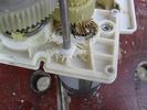
Gear box casing showing wear from screaming friction...409 views...once the circlip has bust through the inadequate retaining land, the spring presses on the (other) gearbox casing, forcing the secondary gear to wear on the gear box casing where shown, there being no adequate provision for end-thrust (even though helical gearing would mandate that, to cope with the NORMAL axial vector forces produced) resulting from spring pressure on the other gearbox casing face pushing the gear into this face.
|
|
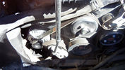
67 viewsThis is easy to remove. You will notice the tensioner at the bottom left near the alternator. There is a sqaure slot on the tensioner into which fits a 3/8" square drive. Just turn anti-clockwise and the tensioner is moved away to slacken the belt and off it comes.
|
|
85 viewsMuddy LR3, and a grand view all the way into Nevada
|
|
120 viewsThe signal wire then drops into the aux battery box and through the bulkhead grommet
|
|
Splash-ette137 viewsNot quite extreme fording. Note the way the LR\'s dissapear into the background like camouflage.
|
|
Stuck D454 viewsCrack Recovery Team Jumps into action
|
|
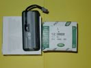
Upper Hatch Release Switch LR Part Number YUZ500020676 viewsThis is the Range Rover Sport switch, Land Rover part number YUZ500020, as it comes out of the box. Note the JAE, (Japanese Aviation Electronics), male wiring connector installed on the end of the power lead.
The rubber cover of the switch is sealed to the plastic body of the switch whereas in the previous switch design, there was no sealing. Also the replaced switch was hard wired into the same harness as the license plate lights - no JAE connector in other words.
|
|

Thread upload29 viewsImage uploaded in thread 136445
|
|
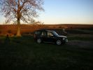
The \'Serengeti\' of The North York Moors891 viewsPicture was taken on a late sunny winters afternoon in the North York Moors National Park. The low light captures the Sky, Tree, and the D3\'s light interior along with the silver exterior detail. Whilst the dark D3 body blends into the foreground. Gives a feel of the South African plains. Think would make a good October or November page??
|
|
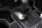
Small Kensinton trackball used to move the mousepointer while driving116 viewsUnfortunately the touchscreen does not work while connected to the PDA. A small bluetooth trackball solves this. All functions of the pda can be used doing this. Windows mobile has an onscreen keyboard which can be operated with the trackball as well.
|
|

A keyboard can be used100 viewsThis little bluetooth keyboard can be used to enter text into the pda. It also has a tiny touchpad so the mousepointer can be used as well
|
|

Airbag removal tool249 viewsMake something like this out of welding rod or coathanger
Picture courtesy of Alinton ( hope you dont mind ..if you do just say and i will remove )
|
|
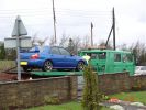
Good Old Jap Cr@p!!340 viewsSuspension threw a woddler and nearly popped me into a tree at xxxmph!! My luckiest day in motoring ....ever!!
|
|

Thread upload3 viewsImage uploaded in thread 121845
|
|
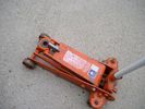
Trolley Jack Adapter824 viewsThis shows my 2.5 long ton, (2,540 kg, 5,600 pounds), trolley jack with the pin adapter that slots up into the round holes on the underside of the frame.
Use of the adapter when lifting by the left rear wheel ensures that I will not be jacking on the air compressor support; on the other three corners, it is much safer than merely jacking directly on the nearly flat narrow underside of the frame rail.
|
|
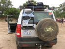
Botswana244 viewsYou never know what you can bump into in the Motloutse river bed.
|
|

Heading out into the Desert after the Oasis146 views
|
|
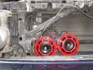
Hella Twin Tone horns in place of existing228 views
|
|

Typhoon into C130224 views
|
|

51 views
|
|
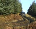
RRS disappears into the distance86 views
|
|
Voss System 203 connector 6 mm for valve blocks 905 viewsThis is Land Rover part number RQC000030, the Voss fitting for the axle valve blocks. I think it is a Voss System 203 6mm fitting, Voss part number 5 2 03 11 01 00.
The parts bag comes with the white plug inserted in the brass threaded bit with what is called the brass cutting ring placed on the tip of the white plastic plug. The idea is that one screws, (M10 x 1 thread), the brass insert into the appropriate hole with the white plug still in the brass insert. Once the brass is tight, (12 mm wrench), then the white plug is pulled from the assembly leaving the cutting ring down inside and under. One then pushes in the 6 mm tube end about 20 mm or so and the tube slides down thru the brass cutting ring, (2 internal sloped one way cutting ridges). When the tube is in far enough, one pulls upwards a bit and the ring cuts into the plastic such that the tube will not pull out. To remove tube, one unscrews the brass nut and all comes out, sort of like I have shown with the short piece of 6mm tubing. The white plug is a throwaway item upon install of the tubing.
|
|

Voss System 203 Connector cut thru, (similar to in valve block).678 viewsThis is a cut thru of a Voss System 203 connector. The top third of it is similar to the connector that holds the three 6mm plastic tubing lines into each of the front and rear valve blocks.
I say top third, as per the other pictures, the 3 has a Voss assembly that threads into the plastic of the valve block, whereas in the cut thru above, the Voss brass assembly is threading into the brass body of a metric threaded adapter for threading into a standard type metric threaded hole. Note also the two one way sloping ridges of the cutting ring, and the two interal O ring seals that mate with the plastic tubing. There is additionally the small squashed O ring to provide a seal related to the external thread of the Voss cutting ring assembly; (similar to the larger O ring for the brass body external thread).
|
|

Wadi Bani Auf, Oman160 viewsLoose river-borne gravel as the main surface routes from Al Rustaq into the Grand Canyon separating Jebal Achter and Jebel Shams
|
|
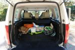
117 viewsrear view shows that Tundra colour does not extend into cargo area.
|
|
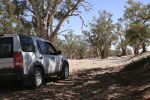
Willochra Creek849 viewsCALENDAR 2008 ENTRY
parking in the shade for some tea and lunch in Willochra Creek bed which drains into lake Torrens in South Australia. Three weeks prior, this creek was 300m wide with recent flooding rainfalls.
|
|

Overlaid wires95 viewsOverlaid wires draped to floor ready to be inserted into loom.
|
|
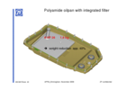
ZF_6HP26_Plastic_Filter_Pan_ combo.png1103 viewsThis is the plastic oil pan on the bottom of our ZF 6HP26X transmissions. Note the two round magnets at the right end of the pan; the drain plug is between them. The filter is the grey part and the vertical oil suction pipe is to draw oil up to the transmission from the filter element. There are 21 Torx screws around the perimeter and the pan gasket is O ring like in design where a half round channel is moulded into the plastic of the pan. The metal pan uses a more conventional flat gasket and in both cases, the metal mating surface of the transmission case is a flat machined metal surface.
|
|

Mechatronic Replacement Hints plus drains for steel and plastic pans1111 viewsThis 22 page pdf shows colour views of the Mechatronic unit as well as good illustrations of the drain and fill ports in both the plastic, page 17, and steel pans, page 18.
Page 8 details the replacement of the sealing sleeve where the electric wire feed thru the case into the Mechatronic unit. The seal is normally replaced when a new pan is installed as the seal is a known leakage point.
|
|
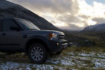
Glenshee - Scotland.507 viewsA quick trip up to Glenshee for some hill walking and were luck enough to spot the first snow of the season. Stunning views all around. Even bumped into a guy who had lost his trained Peregrine Falcon that hadn't come back. I don't blame the Falcon to flying off in scenery like this!!.....
|
|
|
|