| Search results - "instructions" |

0000 LR Bluetooth dealer Kit install instructions1608 viewsThis 17 page pdf is mostly a series of pictures showing how to install the original Land Rover dealer installed Bluetooth kit for circa 2005 / 2006 three's. Also included are three wiring diagrams sheets related to the pairing code 0000 Bluetooth install.
This pdf is useful if you are now removing the 0000 kit to install the optical 2121 MOST D4 module, an easier install than the 0000 kit ever was.
|
|

Handsfree tele-mute lead 06-124B instructions128 views
|
|

13 Pin Socket Towing Electrics Fitting Instructions224 views
|
|

load retention rails fitting instructions38 views
|
|

Load retention system fitting instructions47 views
|
|
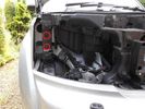
Remove Headlights and Grille using bulb replacement instructions in Manual - Push the fixings supplied into these holes circled in red152 views
|
|

repair instructions159 views
|
|

LR Dog Guard Fitting Instructions80 views
|
|

Alternator and Regulator Wiring Diagrams, TDV6 and petrol V8 and V61989 viewsThis is a three page pdf that shows the alternator and regulator wiring for the petrol V6, petrol V8 and TDV6. The pdf can be either printed or by right clicking on the displayed pdf, rotated as required for viewing.
Of interest is that the regulator gets its instructions primarily from the Engine Control Module (ECM) and only secondarily from the vehicles electrical buss. The conductor from the battery thru the 5 amp fuse F20E is to provide initial power to excite the alternator at startup and then secondarily, to instruct it if the PWM signals were not available. Primary instructions to and from the ECM are thru the two other conductors via a digital like Pulse Width Modulated (PWM) signal.
If F20E, the 5 amp engine compartment fuse box fuse is blown, the red alternator light on the dash will be illuminated. This means that the alternator could be OK, but if the F20E fuse is blown, no electricity will be generated. Hence check the F20E fuse if you get a red ALT light or some indication of the alternator not working.
Regarding operation of the red ALT light on the dash, it is not the regulator within the alternator that tells the red light to illuminate, or not, but instead the ECM. This is the reason the red light does not function in the same manner as with older vehicles. With the 3, sometimes you have illumination and sometimes not depending upon what the ECM is thinking. What this means is that you can have an alternator that is failing but the red light does not illuminate as the ECM is compensating for reduced alternator output - maybe by draining the battery and or cutting back on vehicle electrical loads such as shutting off or cycling the radio amplifier or heated seats.
|
|

501-12-cool-box install instructions / german language66 viewsCool Box Discovery 4 installation instructions - german version
|
|

D4/LR4 501-12-floor console upper panel install instructions / german language72 viewsD4/LR4 501-12-floor console upper panel install instructions / german language
|
|

Rear light guards fitting instructions56 views
|
|

Twin 7 Pin Socket Towing Electrics Fitting Instructions264 views
|
|

Audio Connectivity Module fitting instructions748 views
|
|
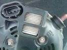
Alternator Plug and B+ terminal918 viewsPictured is the rear of the older Land Rover part # YLE500190 alternator showing the shiny cooling fin of the Regitar VRH2005-142 regulator under.
The first pin in the far left side of the connector is numbered #1 in the LR electrical wiring diagrams and is Battery Voltage Sensing (BVS); the middle pin, #2 receives a Pulse Width Modulated (PWM) signal from the Engine Control Module (ECM), and the right pin, #3 carries a PWM signal back to the ECM. Terminal Pin #2 on the LR wiring diagrams is called Alternator Control or ALT CON; Pin #3 per LR is called Alternator Monitoring or ALT MON.
Pin #1 is similar to what in older designs used to be called A or Batt, but is now called by Denso, S, AS, or Alternator Sensing for this design. Pin #1 also provides power to excite the alternator at startup until the PWM instructions over ride the battery voltage info. Land Rover calls the electronics under the pins a Smart Regulator, ironic, as it has to follow orders from the ECM rather than give the orders - new age thinking I guess. This is different from older design internal regulators that look at just the battery or the electrical buss voltage and then decides itself what to do.
It is almost like we are back to the external regulator designs of old, except that the ECM may decide that instead of telling the alternator to make more power, to load shed, and hence shut down the heated windscreen, seats, or whatever other electrical loads it decides are appropriate. My view is that the "smarts" are in the ECM and that the "regulator" should be regarded if not dumb, then as being a slave to the ECM.
|
|

205 viewsInstallation Instructions for ACM
|
|

OLD VERSION - Bodsy's Brake Bible v 1.611170 viewsUSE Version 1.6a
Clarified EPB shoe instructions & corrected references to other sections. Added paypal donations information (requested by users of the guide.) Internationalised wheel location references by removing UK based reference to OS/NS, replaced with physical Front Left or Front Right descriptions.
|
|

Brake Light Switch, Find, Remove, and Install Instructions 7851 viewsThis is a two page doc outlining where to find the brake light switch, how to remove it, and then install the new one.
Note, do not move the brake pedal when removing or installing the switch. Let the brake pedal hang where it wants to. The switch design is actually cunning, and as such is supposed to make the removal and install fool proof. Hence if you think too much about it, you can wreck the new switch.
If you want to inspect the interior of the switch, wait until you have removed the old switch. You can then just unsnap the blue from the white to get it apart. Inside, the switch is quite simple, (no circuit boards), but it will probably show black dust from failing contacts.
I think the reason the switch fails is that the Normally Open, (NO), contacts of the brake light contacts were made too light to carry the current load for make and break of the tail light filaments. I also think the black dust created then fouls the Normally Closed, (NC), second set of contacts for the ABS circuit. As such, the Normally Closed contacts become intermittent in operation and display as a fluctuating open and closed circuit condition to the ABS system when the ABS should be seeing a steady closed circuit. Hopefully the replacement switch contacts are more robust and may be as I recently replaced my switch again just as a matter of maintenance. While in a redesign, ideally the NC contacts should be sealed or at least separated from the NO contacts, when I inspected the removed switch, this time there was no black dust present.
Probably the removed switch will have a Land Rover oval logo moulded into it, the new one, FOMOCO.
|
|

Build your own Drawer unit115 viewsStep by Step guide to build your own set of drawers.
Instructions by ~Rich~
|
|

15 views
|
|

7 views
|
|
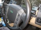
Steering wheel audio controls and iPod dock120 viewsFollowing the instructions I found on Disco3.com.uk it was a breeze the fit the steering wheel audio controls. The iPod dock was a bit more fiddly (took me several hours). Works a treat!
|
|

Instructions on the NEW black badge bits in PDF format397 views
|
|

Fuel Burning Heater Install Instructions (not mine, sorry)575 views
|
|

Collection of EPB instructions & PDF\'s of Brake Posts659 viewsAll you need to change your brake pads or Brake Disks as well as adjuusting the Electronic Parking Brake. Includes the bedding in process for EPB pads
|
|

D3 Kaymar Rear Bar Fitting Sharing20 views
|
|

Thread upload17 viewsImage uploaded in new thread
|
|
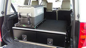
Ironman Drawers and Fridge Slide111 viewsI hate kitsets, over 100 bolts to assemble this unit and lost gallons of sweat, must have read the instructions a hundred times or more but final product does not look so bad. A few bolts hanging out the sides of both slide and drawers that may catch things so time will tell if I made the correct purchase.
Maybe one day I will make some side wings to cover the sides properly.
|
|
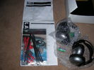
Instructions / parts etc (Un-opened)58 views
|
|

DVB-LR Installation Instructions Pages 1-440 views
|
|

DVB-LR Installation Instructions Pages 5-837 views
|
|

DVB-LR Installation Instructions Pages 9-1356 views
|
|

Pictorial instructions on EPB bedding in mode524 viewsDriving and reading LRs instructions is not easy - I tried this in graphic mode - MIGHT help
|
|

Wynns EGR3 Spray Instructions91 views
|
|
Thread upload22 viewsImage uploaded in new thread
|
|

Fluid, Filter/Pan Combo removal and install5979 viewsThese are the LR instructions re removal and install of the plastic pan/filter combo for the ZF 6HP26X transmission on the 4.4L petrol V8 LR3.
The instructions tend to ignore the reason you have to lift the right hand side of the engine about 40 mm. This is because of a frame cross member that interferes with dropping down of the plastic pan. The real problem is a vertical "oil filter spout" that rises out of the filter/pan combo up into the transmission. The spout is the suction pipe for filtered transmission oil back up into the tranny.
On the metal pan versions, the filter is separate from the pan, hence the filter remains with the tranny when the metal pan is dropped. The filter is then removed or installed independent of the metal pan, hence with the metal pan, there is no need to lift the engine.
If one is removing the plastic pan so as to install the metal pan, then some do not lift the engine but just drop the plastic pan enough to gain access to saw off the vertical plastic spout - it is a one time procedure.
Be aware however that the metal pan uses a flat gasket and the plastic pan uses a O ring like perimeter gasket that sits in a half round groove in the tranny casing. Also the metal pan uses 21 shorter torx M6x22.5 metric cap screws for the perimeter bolts. The plastic pan uses longer M6x28.5 torx metric cap screws.
|
|

Foot Assembly Instructions260 views
|
|

Fitting Instructions251 views
|
|

182 viewsFoot assembly instructions (cont.)
|
|

Official instructions on how to remove the bumper908 viewsWhen removing the front bumper - you start with the front grill, then the headlamps, then the wheelarch trims, then the bumper...
|
|

disco3.co.uk instructions for removing wheelarches (with photos)644 viewsCourtesy of a senior member of the site - detailed instructs for removing the wheelarch trims and front bumper - use in conjunction with the other 2 documents
|
|

Official instructions on how to remove the wheel arch trims624 viewsWhen removing the front bumper - you start with the front grill, then the headlamps, then the wheelarch trims...
|
|

Land Rover TSB LTB00245 install instructions1939 viewsThis is the Land Rover Technical Service Bulletin showing how to install the new breather cap. The instructions are a bit vague re cutting the existing air vent tubing on a 45 degree angle with the cut facing to the rear.
|
|

GSM Receiver Instructions109 views
|
|

Reversing camera sat nav land rover instructions hids4u506 viewsReversing camera retrofit on land rover lexus jaguar and many other cars. Display image on the sat nav lcd screen
|
|

Curt Manufacturing Installation instructions Class III345 viewsThese are the instructions for installation of the Curt Hitch.
|
|

Stainless Steel Accessory Instructions356 views
|
|

Rear Spoiler Fitting Instructions LR131 views.
|
|

FL2 MOST Bluetooth Instalation Instructions97 views
|
|
Thread upload1 viewsImage uploaded in new thread
|
|

37 views
|
|
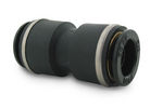
John Guest DOT all plastic fitting717 viewsThis is a picture of the John Guest DOT all plastic union. If you look closely, you can see the DOT imprinted in raised letters on the end of the fitting. This is of a 1/4" connector rather than the 6mm that the 3 requires.
The picture is similar to the air suspension pneumatic fitting union that Land Rover sells as replacement part # STC8580. This is for 6mm OD tubing size. The STC8580 comes with what are called "Collets" at each end that cover up the press to release feature underneath. See the John Guest web site www.johnguest.com under the Pneumatics section and also in Downloads for their catalog for install and remove instructions.
The actual "air brake spec" fitting that Land Rover provides has an interior 4mm OD ferrule that slips inside the 4mm ID of the nominal 6mm tubing. I have not yet been able to obtain the John Guest part number for the LR fitting, only the LR part number. This part number was generated for the RR Classic air systems.
|
|

John Guest (LR part # STC8580) push in straight 6mm tubing to tubing connector730 viewsThis picture is similar to the air suspension pneumatic fitting union that Land Rover sells as replacement part # STC8580. This is a 6mm OD tubing size push in to install straight tubing to tubing fitting. The STC8580 comes with what are called "Collets" at each end that cover up the press to release feature underneath. See the John Guest web site www.johnguest.com under the Pneumatics section and also in Downloads for their catalog for install and remove instructions.
The actual fitting that Land Rover provides has an interior 4mm OD ferrule that slips inside the 4mm ID of the nominal 6mm tubing. Hence the fitting depicted and part number are not actually correct. I have not yet been able to obtain the John Guest part number for the LR fitting.
The fittings that show in this doc are what I call food service fittings rather than transportation or Air Brake fittings. The part LR sells, (STC8580), is the Air Brake type for transportation.
|
|

KDB500010 D3 Fire Extinguisher3 viewsInstallation instructions for D3 fire extinguisher.
|
|

instructions for Webasto timer install203 views
|
|

LED trailer lights adapter for LR3843 viewsThis doc includes a partial list of materials and the instructions/links required to construct an adapter to prevent LED trailer lights from pulsing due to the 3's diagnostic circuits interrogating the signal light circuit.
Using the adapter also facilitates the green flashing of the dash located trailer indicator when the signal lights operate plus inhibits operation of various systems such as the backup sensors, etc.
|
|

Instructions for the connects2 interface215 views
|
|

Rear lamp guard fitting instructions406 views
|
|

LR3 TDV6 RRS TDV8 Engine Pre-heating Operating Instructions - Appendix343 viewsThis is the instructions you get with the LR original Webasto timer kit
|
|

SDARS Satellite radio operating instructions 352 viewsThis is a 14 page pdf portion from the Owners Handbook with regard to operation of the satellite radio system operating on the Sirius channels.
|
|

front runner spare wheel carrier instructions111 views
|
|

How to cable factory BT module (including MOST bus connector)85 viewsInstructions to install Factory BT module in a Disco 3 that has LR aftermarket or no BT module installed
|
|

Crop from LR Driving Liight fitting instructions showing Nudge Bar bracket410 views
|
|

74 views
|
|
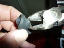
firewall plug run722 viewsThe rubber grommet from firewall plug, removed, with a hole cut in the middle. Instructions say to cut it to the center, but you can cut a hole out by bending it, and using a pair of diagonal pliers, removing excess material so you can fit the plug back in.
|
|
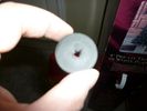
firewall plug run663 viewsThe rubber grommet from firewall plug, removed, with a hole cut in the middle. Instructions say to cut it to the center, but you can cut a hole out by bending it, and using a pair of diagonal pliers, removing excess material so you can fit the plug back in.
|
|

32 views
|
|

Instructions & advise on replacing the pollen filer275 views
|
|

RAI Instructions101 views
|
|

RAI instructions176 views
|
|

6 views
|
|

LR Read Mud Flap Fitting Instructions133 views
|
|

Rear Bumper Removal Instructions9 views
|
|

Rear Lamp Guards Fitting Instructions28 views
|
|

11 views
|
|

Roof Rack Fitting Instructions27 views
|
|

Rosen A10 Manufacturer Installation Manual763 viewsThis is a 30 page pdf from Rosen that explains how to install the A10 unit. It is Generic in nature and hence carries detail not found in the LR specific install instructions. It also uses words and pictures instead of just pictures, hence can be a bit easier to figure out, particularily if you wish to take advantages of some of the hidden features not described in the LR material.
One of these features is how to hook up to a headrest display or I suppose even to the NAV in front.
|
|

Thread upload14 viewsImage uploaded in new thread
|
|

CounterAct LT-2 Install Instructions173 viewsThese are the instructions for installing the CounterAct coupler pads (2) and the power supply.
|
|

ScanGauge II Manual 341 viewsThese are the setup instructions etc for the ScanGauge II version 5.1 There are newer versions that can be downloaded from the website www.scangauge.com as the software is subject to update; also the ScanGauge unit you purchase can later be sent in for updates as you might wish.
|
|

SideSteps Installation Instructions500 viewsLR Official fitting instrutions for LR SideSteps
|
|

23 views
|
|

STC8138AB Generic Land Rover Fire Exinguisher6 viewsInstallation instructions for generic Land Rover fire extinguisher.
|
|

16 views
|
|
![Filename=Technical Service Bulletin SB034 SB036 Vehicle Enhancement Program[1].pdf
Filesize=959KB
Dimensions=0x0
Date added=17.Jun 2010 Technical Service Bulletin SB034 SB036 Vehicle Enhancement Program[1].pdf](images/thumb_pdf.jpg)
Technical Service Bulletin SB034 SB036 Vehicle Enhancement Program2390 viewsOn page 6 and following are the Land Rover service bulletin instructions as to how to install delivery valve and exhaust valve repair kit JPO500010; also a list of previous compressor model numbers as related to the 3. The new delivery valve is easy to install, the exhaust, not so easy. Note that this in not the more recent TSB that reduced the operating pressure of the compressor via a software fix and also recommended replacement of the air compressor 70 amp relay. See the F35 album near the bottom for the relay material.
|
|
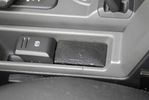
Little speaker to get nav instructions while listening to the radio131 viewsThe sound of the PDA is routed to the Aux input of the car. this way MP3 music and Nav instructions get to the car\'s audio system. But when you want to listen to the radio and also hear nav instructions, you can\'t hear them both through the car radio. For that I mounted a little speaker.
|
|

Tow Assist instructions227 views
|
|

D4 Rear Lamp Guards Fitting Instructions46 views
|
|

VPLAS0041 D4 Fire Extinguisher7 viewsInstallation instructions for D4 fire extinguisher.
|
|

webasto oval timer instructions.pdf363 views
|
|

webasto oval timer instructions115 views
|
|

Thread upload18 viewsImage uploaded in thread 135908
|
|
![Filename=webasto_oval_timer_instructions[1].pdf
Filesize=111KB
Dimensions=320x240
Date added=19.Oct 2011 webasto_oval_timer_instructions[1].pdf](images/thumb_pdf.jpg)
210 views
|
|

19 views
|
|

ZF Gearbox Servicing Instructions57 views
|
|

ZF 6HP26 and 6HP28 Comparison plus oil pan and filter replacement options962 viewsThis is a 66 page ZF produced pdf that provides comparisons between the various ZF transmissions; also instructions regarding maintenance of the Mechatronic unit, the round seal; the various metal and plastic pans available as well as tips regarding changing the oil.
This ZF pdf has a number of colour pictures and part numbers within as well.
|
|

Mechatronic Sleeve Removal and Install Instructions1057 viewsThis 3 page pdf with pictures shows how to remove and install the Mechatronic sleeve that tends to leak tranny oil after about ten years. Even if not leaking, replacement when doing a pan/filter change at the ten year mark is suggested.
Note the 3mm or less requirement when sleeve installation is completed; also that rotation of the sleeve during the install procedure can do damage to some internal pins - hence do not rotate the sleeve when trying to insert it or in getting it to lock in place - not so easy it seems.
|
|

ZF6HP26X fluid fill checking procedure2256 viewsThis are the single page ZF instructions for checking the fluid level in the 6HP26X six speed automatic that is in the LR3.
Included sketches show where the fill and drain plugs are located and that it requires a 8mm hex wrench for the filler plug and a 10mm for the drain for the plastic pan.
|
|
|
|
|
|