| Search results - "fuse" |

51 viewsD44 front winch bumper. Ali washer bottle. D44 rear h/d bumper. centre diff lock. 235x85x16 pirelli muds. OME +2" springs & shocks. front diff guard. side tree bars. wired for roof CB. Aux fuse block. safari snorkel. extended wading tubes. the list goes on...
|
|

find relay 7 in engine compartment fuse / relay box 802 views
|
|

fuseable link 79 views
|
|
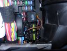
Permanent 12V supply271 viewsPhoto taken of TFC\'s D3 showing where you can take a permanent +12V supply, from the main fuse board behind the glove box.
|
|

Area of the new housing expansion south of Swindon.144 viewsFlood plains will be flood plains - insurance anyone? Oh sorry forgot; all top 8 insurance companies refused to insure a house in this area, so the developers are going ahead building anyway...
|
|
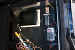
97 viewsDeciding on a layout for the electrical stuff. Bottom right of pic is a fusebox which will take the input power from the traxide kit, then relay box and 12V regulator, ignition busbar and homemade regulated 12V busbar. Big black box is the CarPC
|
|

2011 passenger fuse box layout50 views
|
|

mystery fuse33 views
|
|

Alternator and Regulator Wiring Diagrams, TDV6 and petrol V8 and V61989 viewsThis is a three page pdf that shows the alternator and regulator wiring for the petrol V6, petrol V8 and TDV6. The pdf can be either printed or by right clicking on the displayed pdf, rotated as required for viewing.
Of interest is that the regulator gets its instructions primarily from the Engine Control Module (ECM) and only secondarily from the vehicles electrical buss. The conductor from the battery thru the 5 amp fuse F20E is to provide initial power to excite the alternator at startup and then secondarily, to instruct it if the PWM signals were not available. Primary instructions to and from the ECM are thru the two other conductors via a digital like Pulse Width Modulated (PWM) signal.
If F20E, the 5 amp engine compartment fuse box fuse is blown, the red alternator light on the dash will be illuminated. This means that the alternator could be OK, but if the F20E fuse is blown, no electricity will be generated. Hence check the F20E fuse if you get a red ALT light or some indication of the alternator not working.
Regarding operation of the red ALT light on the dash, it is not the regulator within the alternator that tells the red light to illuminate, or not, but instead the ECM. This is the reason the red light does not function in the same manner as with older vehicles. With the 3, sometimes you have illumination and sometimes not depending upon what the ECM is thinking. What this means is that you can have an alternator that is failing but the red light does not illuminate as the ECM is compensating for reduced alternator output - maybe by draining the battery and or cutting back on vehicle electrical loads such as shutting off or cycling the radio amplifier or heated seats.
|
|

6 Way Fuse Box9 views
|
|
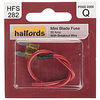
Mini Blade Fuse with Breakout Wire11 views
|
|

C2243R80 viewsDescription: Main harness to engine compartment harness Location: Behind passenger compartment fusebox
|
|

Add A Circuit Littelfuse Data sheet2278 viewsThe switch connects to what Littelfuse brand calls an Add-A-Circuit model FMH200BP which is an adapter that plugs in place of a Mini fuse and then has space for two Mini fuses, (original and a second one). In this install, only the original 5 amp fuse was used - adapter was so as to route power from fuse box thru fuse, then rocker switch, and then back to fuse box.
Before you install the Add A Circuit for this application, take an ohm meter and trace out the circuit path of the four slots that fuses could insert into. The path is more complicated than one might first think. As such, the orientation of the fuse holder in the socket matters for this application - that is for a circuit diverter, rather than accessory adder.
|
|
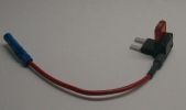
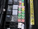
368 views
|
|
Fuseable link for rear windows 18e (50amp ) bottom right hand red square 144 views
|
|
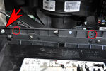
Fuse box earth17 views
|
|
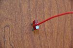
Fuse with cable71 views
|
|
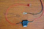
Loom with fuse72 views
|
|
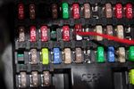
Power taken from fuse 2867 views
|
|

Blade Fuse Specs Ohms57 views
|
|

Black Deposits to interior of Brake Light Switch2862 viewsThere are two contacts, one on each side of the vertical plunger under the copper metal. The set of normally open contacts on the left side that carries the power for the brake light filaments, (15 amp fuse F15P), is apparently not heavy enough as the contacts deteriorate and generate the black residue.
The set of normally closed contacts on the other side appear to be sized OK. There is not as much current, (5 amp fuse F66P), flowing thru the contacts to the ABS module, however the contacts are likely adversely affected by the black residue produced by the other deteriorating set of contacts.
One presumes/hopes that the newer replacement switch now has contacts heavy enough to carry the brake light power. It would be ideal if the ABS set of contacts were sealed from the brake light contacts to prevent contamination of the normally closed set of contacts.
|
|

21 views
|
|
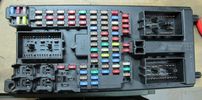
203 viewsfuse plane (this is what you see behind the glovebox)
|
|
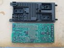
central junction box, without fuses.204 viewsthe print circuit board is easily dropped, after you pull out all the fuses.
|
|
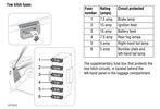
Thread upload27 viewsImage uploaded in thread 157372
|
|
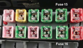
D3_link_fuse_14_and_1616 views
|
|
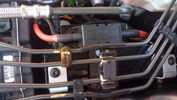
100A fuse mounted in secondary battery compartment15 views
|
|
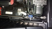
Fuse mounted in secondary battery box111 views
|
|
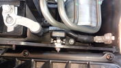
Fuse mounted in secondary battery box95 views
|
|
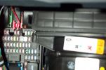
Tapa-circuit388 viewsTapa-circuit fitted to fuse box behind glove box. Red cable to top is the fused output cable leading to the PDA charger
|
|
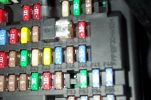
Tapa-Circuit Fuse Tap411 viewsTapa-circuit fuse tap fitted in existing fuseway provides extra fuseway which I have used to hard wire my Tomtom Sat Nav PDA. The fused output feeds into a female socket (Cigar lighter sized) into which the tomtom power adaptor is plugged. All hidden away behind the glove box.
|
|
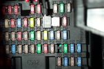
Tapa-circuit Fuse Tap435 viewsTapa-circuit fuse tap fitted in existing fuseway provides extra fuseway which I have used to hard wire my Tomtom Sat Nav PDA. The fused output feeds into a female socket (Cigar lighter sized) into which the tomtom power adaptor is plugged. All hidden away behind the glove box.
|
|
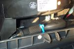
Hard wired tomtom498 viewsThe fused output from a tapa-circuit feeds into a female socket (Cigar lighter sized) into which the tomtom power adaptor is plugged. All hidden away behind the glove box.
|
|
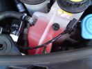
you can see the fuse on the L and the relay on the R174 views
|
|
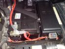
Main battery and accessory fuse box216 views
|
|
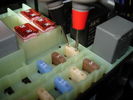
Voltage Drop on 25A36 views25 Amp Fuse = 2.36mOhm or 0.00236 Ohms
Measured @ 0.0235v or 23.5mV
= 9.95763A ~ 10A
|
|
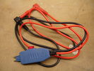
Fuse Buddy24 views
|
|
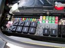
Eng compartment fuse box16 viewsEng compartment fuse box
|
|

56 viewsfbh fuse location in engine bay fuse box
|
|
16 views
|
|

FUSE SPECIFICATION CHART66 views
|
|
52 views
|
|
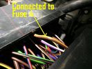
44 views
|
|
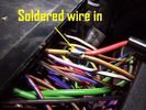
46 views
|
|
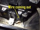
47 views
|
|
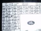
73 views
|
|
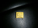
Fuse53 views
|
|

Thread upload9 viewsImage uploaded in thread 171808
|
|

Thread upload0 viewsImage uploaded in thread 141032
|
|

Thread upload0 viewsImage uploaded in new thread
|
|

Thread upload37 viewsImage uploaded in thread 112564
|
|

Thread upload22 viewsImage uploaded in thread 112564
|
|
Thread upload18 viewsImage uploaded in thread 112564
|
|

13 views
|
|

Thread upload15 viewsImage uploaded in new thread
|
|
Thread upload12 viewsImage uploaded in thread 174350
|
|
14 views
|
|
Thread upload4 viewsImage uploaded in new thread
|
|

Thread upload5 viewsImage uploaded in thread 40682
|
|
Thread upload13 viewsImage uploaded in new thread
|
|

412 viewsID of washer fuse and fuse "pincer" tool
|
|

47 views
|
|

27 views
|
|
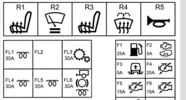
Thread upload13 viewsImage uploaded in new thread
|
|
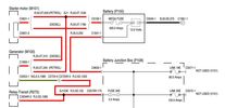
Thread upload21 viewsImage uploaded in thread 175669
|
|
Thread upload15 viewsImage uploaded in new thread
|
|

Thread upload21 viewsImage uploaded in thread 172761
|
|

Thread upload1 viewsImage uploaded in thread 43242
|
|
24 views
|
|

Thread upload2 viewsImage uploaded in new thread
|
|

File - Fuse_Voltage_Drop_Chart_-_Cartridge_Fuse29 views
|
|

Fuse Voltage Drop Cartridge40 views
|
|

File - Fuse_Voltage_Drop_Chart_-_Maxi_Fuse20 views
|
|

File - Fuse_Voltage_Drop_Chart_-_Mini_Fuse24 views
|
|

Fuse Voltage Drop Mini58 views
|
|

File - Fuse_Voltage_Drop_Chart_-_Standard_Fuse23 views
|
|

90 viewsRed FBH WBUS wire behind fusebox CJB
C2411 C2412
|
|
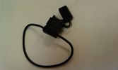
Waterproof fuse holder67 views
|
|
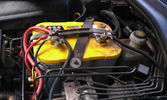
The auxiliary battery21 viewsThe auxiliary battery in the bay.
As the wiring diagram I made shows, there's a wire leading to the fuse box in the rear. (is going through the key-switch)
The second one is going to the fog lights. The smaller cables which should be connected to the head-lights, are connected to the battery.
The third one is going to the compressor (via a switch) (sits before the key-switch)
A fourth one is going to the CB and battery check display (sits before the key-switch)
|
|

Close up - key in place16 viewsThe key placed and turned in order to turn the switch on.
Everything connected to the fuse box in the rear and the fog lights on the roofrack will work now.
|
|

An extra 12V outlet16 viewsOn the passenger side, I added a 12V outlet which is fed through the fuse box in the rear and adds as such an outlet for whatever charger we don't want to have lingering around around the central console.
The USB charging outlets are visible as well :)
|
|
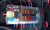
Fuse box in the rear15 viewsI installed the fuse box in the rear. Since I do have a 5-seater, there's plenty of space in the booth beneath the 2nd cover, which rests behind the second row seats.
|
|
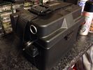
33Ah leisure battery in ABS case with Fused 12v socket48 views
|
|
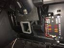
Aux battery fuse box18 viewsMy install of a fuse box.
|
|

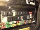
Aux battery fuse box19 viewsClose up of fuse box
|
|
Fuses25 views
|
|

Fuses28 views
|
|
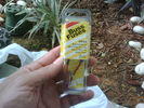
add a fuse19 views
|
|
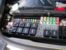
Picture of the engine compartment fuse panel5780 viewsEngine compartment fuse panel located near the battery. This is where F3E, (5 amp), F26E, (20 amp), Fuseable link 10E, (60 amp) and Relay 7E, the now upgraded 70 amp air compressor motor relay, part number YWB500220, (E is for Engine compartment fuse box), are all located. Fuse F35P, (5 amp), is inside the Passenger compartment behind the lower glove box door.
To keep the suspension from going down to the stops when driving, (or parked), it appears that it is only really necessary to remove F26E to depower the exhaust valve and generally keep all the valve block solenoid valves in a closed position trapping whatever air is within the air springs. F3E gets its power thru F26E, so when F26E is removed, the F3E circuit is automatically de-powered. F35P is more interesting in that battery power goes thru the ignition switch and F35P and then into the air suspension control unit. Apparently however, if F26E is removed, removing the F35P is not needed even when the engine is running.
With all fuses still in, if you have a problem, in practice, ideally, the compressor still works and will raise the 3 to an appropriate height. If so, one can then shut the engine off and allow the computers to go to sleep and then you remove the fuse(s). In actual practice, it seems that one need only pull the F26E fuse and can do so with the engine running. All the same, one might consider that the 3 is first a mobile computer, and secondly a 4x4. Computers prefer to go to sleep before the plug is pulled on them, however given that F26E circuit is always alive, then the computer never sleeps. With the fuse(s) pulled, and if you are still up, you can now be a 4x4 instead of a low rider. The whole purpose of the fuse pulling exercise is to depower the one and only system exhaust valve that is physically located within the compressor unit, (to keep it from opening), and secondarily to keep closed the four air spring solenoids within the block valves. This also shuts the air compressor down and stops the air compressor from making air even if the compressor is still good. That is why you initially need the fuse(s) in to allow the compressor to make air if it can.
|
|
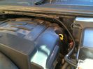
4GA Power Cable16 viewsFrom fuse box on aux battery - along channel.
|
|

PP002 12V135 views Brad Harris Socket
Hella Socket Cigarette
Lighter Socket
Battery Level Meter
External Terminals for Battery Charger or Solar Panel
ON/OFF isolator tie down strap excludes Battery
Built in fuses
https://www.facebook.com/snomasterusa
|
|

Connected to the Rear Seat Heat fuse39 views
|
|

Key in Ignition Electrical Wiring Diagram1051 viewsThis shows the key in ignition wiring, (LGW, 1.5D), running from the key lock cylinder to the Central Junction Box, (CJB), thru 5 amp fuse F40P, located in the fuse box behind the lower glove box door.
You can remove the 5 amp fuse and the good news is that the ignition chime will not sound any longer; the bad news is that a bunch of other circuits that rely on knowing if the key is in or out no longer work.
Also note the Transponder Coil D219 reference.
|
|

Air Suspension System Parts, Layout, and Operation7062 viewsThis 22 page pdf gives a pretty good description of how the system is supposed to work, plus shows the various parts and the electrical including fuses and relays etc. Of the files here, this is the most useful.
As with all the pdf's here, you can download and print it out.
|
|

Harness that connects inside left rear compartment.445 viewsThis is the harness section that connects behind the left rear interior access panel and exits thru the large grommeted hole to below/behind the left rear tail light.
Note the two rubber grommets on the harness as there is both an interior metal skin and an exterior metal skin behind the left tail light assembly.
The two light grey connectors plug into two existing connectors near the top of the rear left interior access panel. The two darker connectors plug into the second piece of harness.
There is no little separate fuse box either with the NAS spec harness. The fuse box is included with the UK 13 pin dual plug units. If there was a fuse box, it would be on this portion of the harness.
|
|

Littelfuse Add-A-Circuit MINI and ATO style data sheet150 viewsPDF from Littelfuse showing both the MINI and ATO style of fuse holders. The 3 uses the MINI size of fuse. The MINI Add-A-Circuit can be inserted in place of one of the existing fuse panel MINI fuses. The removed fuse is then inserted into the lower slot of the Add-A-Circuit and a second fuse in the second slot to protect the device that you are adding. The Add-A-Circuit is designed for a max of 10 amps on the second load, and I guess maybe the original circuit as well.
|
|
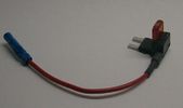
Littelfuse Mini Add-A-Circuit FMH200BP and OFH0200ZP1623 viewsFound this jpg somewhere on the forum - others are using them as it is a good way to tap the fuse box to add a fused circuit, or in this case, to modify a circuit to add a switch such that the fused circuit is switched. In my SmoothTalker gallery, there is a PDF from Littelfuse specifically related to this Add-A-Circuit device.
Before you install the Add A Circuit for any application, take an ohm meter and trace out the circuit path of the two pair of slots that fuses could insert into. The path is more complicated than one might first think. As such, the orientation of the fuse holder in the socket may matter depending upon the application. If the application is a circuit diverter, (as the F35 mode is), as opposed to a mere accessory adder, orientation matters.
|
|
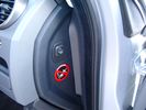
Air Suspension ECU Fuse 35P cut off switch.3821 viewsThis shows the SPST rocker switch mounted in the blank plate installed in lieu of a manual passenger side air bag shut down switch - now automatic via passenger seat pressure switch. Fuse 35P (5 amps) is located in the interior fuse box behind the lower glove box and protects the ignition power supply to the Air Suspension ECU. When the SPST switch is moved to the OFF position, the RAISE /LOWER switch on the centre console is not powered, and hence does not function. As such, some signals from the wheel height sensors and CPU are ignored. By itself however, removing F35P will probably not stop the 3 from self dropping, particularly after the engine is turned off.
Fuse F3E, (5 amps), located in the engine bay fuse box by the starting battery protects the circuit that provides feedback to the Air System ECU indicating that the Compressor Relay has successfully operated and that the Air Compressor is or should be operational, can also be removed, (but is probably not totally necessary), as it gets its power thru F26E. Hence Fuse F26E, (20 amp), also located in the engine compartment fuse box is the fuse that must be removed. This fuse protects the circuit that provides full time battery power to the Air System ECU. When in place, current thru the fuse powers the periodic re-levelling action, (usually lowering a bit with that brief air release noise), that often occurs when the vehicle is parked and the engine is off.
Removing F26E fuse will stop the auto levelling action and also inhibit any other down to the stops signals, (engine running or not). When F26E is removed, no power can flow thru to F3E, hence removing F3E is more for insurance than an absolute requirement. The same with F35P, removing F26E removes primary full time power from the Air Suspension ECU, and hence removing the F35P fuse should not really be required either as long as F26E has been removed.
|
|
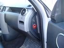
Air Suspension ECU Fuse 35P Shut Off Switch2635 viewsA more distant view of the shut off rocker switch in the ON position which is the normal position for when all is working as Land Rover intended.
Ideally, (but not totally necessary), the F35P circuit should be powered or de-energized after the various computers have gone to "sleep".
Similarly, removal of the F26E or F3E fuses is preferable after the computers have all gone to sleep but it appears that no real damage will be done if the fuses are removed while the system is energized. Pulling F26E is the main full time fuse that powers the air suspension computer. As such, once F26E is removed, pulling F3E is not really required.
Power for the compressor goes thru the 60 amp fusible link and relay, however control of the relay is via the air suspension computer so depowering the air suspension computer effectively depowers the air compressor and the internal exhaust valve relay/port.
|
|
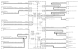
Power Window Circuit centered on Central Junction Box (behind glove box fuse panel)736 viewsRelay 143, the power window relay, and most other relays and FET's as well are built into the back of the passenger side behind the lower glove box fuse panel.
As such, the relays etc are not removable, jump-able, or serviceable.
|
|
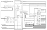
Power Window Circuit Sheet 1 from Battery to Central Junction Box (fuse box behind glove box)353 views
|
|

LR3 Electrochromatic Interior Rear View Mirror wiring diagram.854 viewsIt seems that there are two fuses, F69P and F5P that provide power for the interior rear view mirror. Ten amp F5P is a feed off the reverse gear relay and inhibits auto dimming when reverse is selected. Five amp F69P provides power to the auto dimming circuits and the garage door opener function if optioned.
The pdf can be downloaded and printed out. For on screen viewing, right click on the pdf and select the Rotate Clockwise button.
|
|

Underhood Fuse and Relay Box drawing 3055 viewsShows the various fuse and relay locations. Fuse 3E, (5 amp), and Fuse 26E, (20 amp), as well as upgraded 70 amp Relay 7, part number YWB500220, locations are displayed. Relay 7 sends battery power to the compressor from the 60 amp fusible link called up as 10E. Fuse 26E is what provides full time always on battery power to the air suspension ECU and hence powers the auto level wakeup when the vehicle is shut down and say parked for the night. Removing F26E is the primary method to disable the air suspension system; Removing F35P is more if you want to experiment with it from inside.
I found it useful when I had a suspension problem, (actually a wheel alignment problem picked up by the steering wheel angle sensor), that only showed itself on the highway but allowed for no trouble light driving in the city. This was because in the city, the steering wheel was always in motion and rarely was the vehicle driven in a near straight line for very much distance.
|
|

we put the fuses in the rear panel as well as the air tank gauge, air switch, and battery switch.417 views
|
|
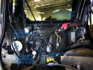
a few items being built in behind cover panel.443 viewsred inverter will have fluch mount plugs, air outloet will be flush, guage with window in lower pop-panel and switches and fuses for all rear items behind popout panel.
12v sockets being added as well, high and low.
|
|

Air Suspension Wiring Sheets3037 viewsThese two sheets show the wiring and fuses related to the operation of the air suspension system. Fuses F3E, F26E, and F35P are shown as well as the interior up down switch and the wheel height sensors.
As with all pdf's, you can rotate them to view plus download and or print out as you wish.
|
|

Power and Heated Seats Electrical Schematic979 viewsThis 6 page pdf shows the wiring for the power adjustment of the front seats and seat heating for all the seats.
Re seat movement or the lack of, not only are there four related fuses, two 30 amp and two 5 amp, (one of each per seat), there are are two separate ground wires, perhaps of more significance than the power, if all movement on either side quits.
|
|

Horn Wiring Circuit LR3578 viewsThe is the wiring diagram for the dual horn circuit.
The Horn Relay, (R133), is not a big black thing hidden somewhere but instead what is called a FET, (and it is hidden)!
This is a Field Effect Transistor that is built into the circuit board that is mounted to the back of the fuse box that is located behind the lower glove box door on the passenger side of the 3. The related 15 amp fuse, 12P, is mounted in this fuse box and is often called F12P, where F is for fuse, and P is for Passenger compartment.
This is to help differentiate from another fuse and relay box, (the usual kind), that is located beside the starting battery in the Engine compartment. FxxE is often used in the naming of those fuses.
|
|

Heated Windscreen Wiring Diagram408 viewsThis single page pdf is the heated windscreen wiring diagram. You can rotate the view by right clicking on the pdf and of course it can be printed out as well.
Relay R208 in the pdf is relay R9 in the Engine Compartment fuse box. Note both 30 amps fuses, F15E and F18E, also located in the Engine Compartment fuse box. If one side of your windscreen does not heat, the problem may be one of the two fuses.
|
|

Thread upload21 viewsImage uploaded in thread 110432
|
|
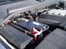
Main starting battery showing 1/2" hole drilled for power cable egress910 viewsView of OEM battery in Left Hand Drive LR3. This is supposed to be a Battery Group BCI 49 or H8 sized battery but in reality is the slightly shorter BCI 94R or H7 battery that fits easier lengthwise, (12 3/8" vs 14").
Note the 10mm hole drilled in plastic of surround to allow for entry of main power cable that runs between batteries. The cable bolts to a spare 6mm threaded hole in the OEM battery cable end; the light gauge wire runs to the front of vehicle to a connector for the CTEK MULTI US 3300 charger. Coloured felts, (red and green), are a material treated to reduce battery post corrosion. The OEM battery ground cable is only about a foot long and runs to an 8mm stud located on the inner fender just to the rear of the fuse case.
|
|
47 viewsMaxiFuse
|
|
MaxiFuse253 views
|
|

PDF of Mini Fuse data re LR3 / Disco 3 fuses.1854 viewsThis is just a data sheet regarding the MINI fuses that are common in the 3.
|
|
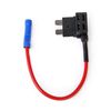
Thread upload12 viewsImage uploaded in thread 163237
|
|

31 views
|
|
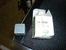
Relay Change246 viewsYWB500220 electrical, fuse & relay, relay ENGINE COMPARTMENT, 70 amp 1
|
|
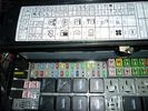
Relay Change379 viewsYWB500220 electrical, fuse & relay, relay ENGINE COMPARTMENT, 70 amp 1
|
|
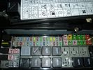
Relay Change285 views
|
|
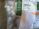
LR020590 KIT - COMPRESSOR 1481 viewsThere are 4 main parts you can get besides a whole compressor. This is the one with only a spring, o-ring and rubber valve.
YWB500220 electrical, fuse & relay, relay ENGINE COMPARTMENT, 70 amp 1
LR020590 KIT - COMPRESSOR 1
JPO500010 KIT - COMPRESSOR 1
VUB504700 - Dehydrator PARTS
|
|
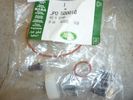
JPO500010 KIT - COMPRESSOR 1437 viewsThere are 4 main parts you can get besides a whole compressor. This is the one with more bits.
YWB500220 electrical, fuse & relay, relay ENGINE COMPARTMENT, 70 amp 1
LR020590 KIT - COMPRESSOR 1
JPO500010 KIT - COMPRESSOR 1
VUB504700 - Dehydrator PARTS
|
|
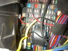
15 Amp fuse connections80 views
|
|
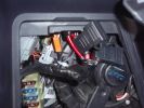
Fuse Panel showing F35P Add A Circuit installed1241 viewsFive amp fuse F35P is located towards the top left in this jpg. The other three Add A Circuit devices are for other items - powering my cell phone base etc.
Note the orientation of the Add A Circuit as this matters. Also one can just see a red tab sticking out from behind the device. The red is the conductor crimp end of a narrow 2.8mm male spade type connector that inserts into one of the "fuse" slots.
|
|

16 viewsWindscreen heater fuses
|
|
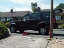
Fitting 17 inch wheels with STs on - confused air suspension202 views
|
|

Fitting 17 inch wheels with STs on - confused air suspension198 views
|
|
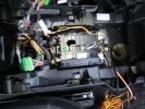
219 viewsThe inner workings of the floor console. You can see the inline fuse holder on the left, which then connects to the chill box connector.
|
|
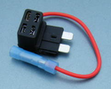
14 views
|
|
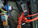
429 viewsRear compartment with my additional wiring and fuses.
|
|
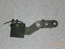
Radio Noise Suppression Capacitor NNW502820699 viewsThis is the radio noise suppression capacitor, part number LR020488 (previous NNW502820), that is mounted underneath and near the transmission. It is powered by fuse 10 amp F30E in the engine compartment. If F30E blows, (the fuse that also powers the transmission ECU), the problem is probably caused by the failed capacitor, not the ECU. A quick fix is just to disconnect the capacitor and replace the fuse as nothing bad seems to immediately result.
The above radio noise capacitor is not to be confused with LR004160, the ignition noise capacitor which is located under the black plastic engine cover on the right hand side above the air intake towards the rear of the engine.
The ignition capacitor is held on with a single 8mm bolt and a three wire electrical connector. Replacing the ignition capacitor as a routine maintenance prevention action at 100,000 miles, 160,000 km), has merit. It is a do it yourself kind of thing and easier to get at than the radio capacitor underneath.
|
|

Thread upload12 viewsImage uploaded in thread 159579
|
|
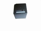
Front Blower R16 relay, part number YWB500060482 viewsThis is the front fan relay located in the engine compartment fuse box. It should be replaced and installed new when a new fan is installed.
|
|
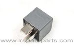
Air Compressor 70 amp replacement relay1393 viewsThere is a software update, 09 April 2010, LTB00270, for the compressor which reduces the shut down pressure to about 205 psig (14 bar). The update is usually done when changing to a new compressor and also includes replacing the R7 relay in the engine compartment fuse box, 07 DEC 2010 LTB00331.
The newer grey case coloured relay, part # YWB500220, shows to be rated at 70 amps, (the relay, not the compressor), however the previous black case coloured relay also indicates 70 amps.
Both the new and replaced relay show on their wiring diagrams to have a parallel voltage spike resistor, (probably 560 ohms), across the coil terminals, #1 and #2. This means one does not just replace the relay with any four prong 70 amp ISO sized relay that one happens upon.
One presumes the grey relay is either upgraded or just being installed for good measure. The relay is common on Ford Fiesta for the seat heater relay, Ford part number 5M5T 14B 192 EA; also Volvo, part number 30765034. The Tyco part number moulded on the grey body is V23136-J4-X62.
|
|

Thread upload3 viewsImage uploaded in new thread
|
|
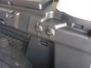
2 new rear 12v outlets933 viewsI added these two after market 12v oulets that are directly wired via a 30amp fuse to the aux battery. Why 2? Well you can never have enuff in my experieince... There\'s also a 12v socket wired to the ignition on the other side.
|
|
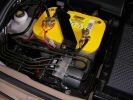
Installed and wired863 viewsShows the wiring loom to the isolator, the feeds (fused link) to the rear outlets and the other feeds are for the battery meter
|
|

Discovery 3 Tow Fuse Box32 views
|
|
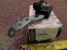
Radio Noise Filter Transmission Electronic Control Unit915 viewsThe jpg shows part number LR020488, a noise suppression capacitor located underneath on a bracket on the right side of the transmission forward of the selector shaft lever. The suppressor is connected to the transmission wiring harness and prevents solenoid operating noise affecting the audio system.
Failure of the capacitor is most often discovered as a result of either black smoke from below and or the blowing of 10 amp fuse F30E located in the engine compartment fuse box. This fuse protects the power circuit to the Transmission Engine Control Unit. When the fuse blows, the engine will still run however you have no gears, hence movement of the 3 is inhibited.
Anything over eight years in service is considered good capacitor life. If the capacitor does fail and fuse 30 blows, a quick fix is just to disconnect the capacitor and replace the fuse.
The capacitor might be missed by the DOT/FCC but the 3 does not seem to mind. With the filter disconnected, solenoid noise might be heard on some radio stations but at least the 3 would be in motion.
|
|

Thread upload6 viewsImage uploaded in new thread
|
|

10 views
|
|
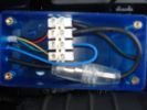
119 viewsConnector block, fuse etc all fits inside. Drilled the holes myself. Should really of used red wire for the +tive, but didnt have any.
|
|

Thread upload17 viewsImage uploaded in new thread
|
|

Thread upload10 viewsImage uploaded in thread 122888
|
|

ZF LifeguardFluid6 transmission oil.1397 viewsThis is an interesting pdf in that under the ZF 6HP26 six speed section, it provides the various automobile manufacturer part numbers for their version of the appropriate tranny oil, all of which seems to be the LifeguardFluid6 oil, ZF part number S671 090 255. Note the fine print and do not confuse it with the LifeguardFluid6 Plus oil for vehicles with the Torsen AWD setup such as the Audi Quattro, VW 4Motion vehicles and I think the BMW FF Range Rovers of an earlier time.
Also of interest at the bottom of the pdf is the recommendation for replacing the transmission oil "between 80,000 km and 120,000 km or 8 years, depending on the load." I also do not see any reference to "sealed for life" but almost as optimistic, "maintenance free" but with the proviso "intended for normal operating conditions". This would most typically be the Sandringham Castle Grounds in the UK rather than Cape York, QLD.
|
|
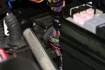
Main loom passes through bulkhead behind the engine bay fuse box next to the battery140 views
|
|
|
|
|
|
|