| Search results - "engine" |

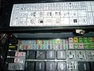
find relay 7 in engine compartment fuse / relay box 802 views
|
|
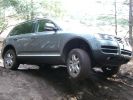
223 viewsThis is the Touareg with the 6cyl engine and rear difflock. did well, useless air-suspension though.
|
|
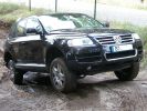
241 viewsThis Toureg is stuck - doesn´t look like it. After 8 hours of driving everyone agreed that with the big 10cyl. diesel engine you should probably oder the rear difflock as well... In this picture the rear left anf front right wheels have no grip, esp or whatever just doesn´t do it.
|
|
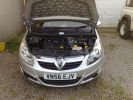
Wheres the engine?61 views
|
|

Engine0 views
|
|

The s2a could not make this one - too deep.446 viewsGot towed through with a dead engine by a Tdi Defender - Betsy is petrol and needed a gallon of WD40 to get going after this!
|
|
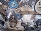
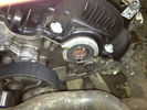
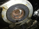
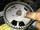
239 viewsPictures of front of engine while doing a timing belt change
|
|

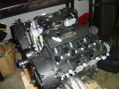
11 Engine - V6 4.0L Petrol15 views11 Engine - V6 4.0L Petrol
|
|
Thread upload23 viewsImage uploaded in thread 118032
|
|
Suspension dragster mode442 viewsAfter I succesfully changed my wintertyres to summertyres, I found out that the front suspension was on access level and rear at off-road. Situation cleared after I switched engine on.
|
|

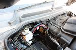
Whatissit139 viewsPicture of a thing in the engine bay, just to the left of the coolant bottle and just behind the edge of the radiator.
|
|
Thread upload12 viewsImage uploaded in new thread
|
|

Oil leak on autobox/engine96 views
|
|

2010 Discovery 4 Data Sheet (all engines)1254 views
|
|

120 viewsTraxide brain mounted. It's mounted slightly tilted towards the front of the engine bay so as to give as much space as possible to the brake vacuum pipe behind it.
|
|
114 viewsBattery to battery cable in place along edge of engine bay
|
|
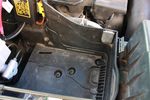
112 viewsDue to the side terminals protruding out the side and affecting the battery clamp, I found the battery will fit better if it could be pushed a few millimeters towards the engine. This lip will have to be removed.
|
|
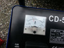
Amps43 viewsThis picture shows how mutch my disco uses while programing the engine management ecu
|
|
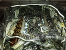
4.4 L Petrol Engine214 viewsIntake removed on V8 4.4L Petrol Engine to remove hose with T in it.
plse like my facebook page https://www.facebook.com/DifferentialPartsUS
|
|

Openreach Test27 views
|
|
Thread upload7 viewsImage uploaded in thread 203917
|
|

Thread upload10 viewsImage uploaded in thread 203917
|
|
Thread upload7 viewsImage uploaded in thread 203917
|
|

Thread upload0 viewsImage uploaded in new thread
|
|

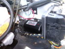
C0506R61 viewsDescription: ABS module
Location: Rear of engine compartment - driver side
|
|

RR Tdv8 Engine22 views
|
|

41 views
|
|

27 views
|
|

RR Tdv8 Engine25 views
|
|
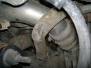
Charge Air Pipe - turbo end.101 viewsThe maint manual identifies releasing the pipe hose clip in the center of the photo. Pity who ever built this engine Put the hose in such a position that access to it was near impossible. I released the other clip at the turbo end of the flexi hose. Easy to get to but a right git to release the hose of the turbo.
|
|

2 Maintenance Schedules - Gasoline Engines17 views2 Maintenance Schedules - Gasoline Engines
|
|

ZF 6HP26 Transmission Cooling System Description and Operation2936 viewsThe five page pdf details the operation of the cooling system as related to cooling engine oil, transmission oil and providing hot water to the cabin heating system.
|
|

Engine Accessory Drive Description and Operation882 viewsThis 2 page pdf shows both belts for the 4.4L petrol V8; the primary serpentine belt, (the long one), and the shorter secondary that drives only the radiator cooling fan.
The various accessory pulleys the two belts are each associated with are numbered and an included table describes each.
When replacing belts and pulleys, count the number of grooves on both your old items and your new replacement parts. It has been known for an pulley with the wrong number of grooves to come with a replacement part or the replacement belt has the incorrect number of grooves; hence make certain the groove count on the new parts are the same as the removed items.
|
|

engine fualts4 views
|
|

3 Maintenance Schedules - Diesel Engines12 views3 Maintenance Schedules - Diesel Engines
|
|

Alternator and Regulator Wiring Diagrams, TDV6 and petrol V8 and V61989 viewsThis is a three page pdf that shows the alternator and regulator wiring for the petrol V6, petrol V8 and TDV6. The pdf can be either printed or by right clicking on the displayed pdf, rotated as required for viewing.
Of interest is that the regulator gets its instructions primarily from the Engine Control Module (ECM) and only secondarily from the vehicles electrical buss. The conductor from the battery thru the 5 amp fuse F20E is to provide initial power to excite the alternator at startup and then secondarily, to instruct it if the PWM signals were not available. Primary instructions to and from the ECM are thru the two other conductors via a digital like Pulse Width Modulated (PWM) signal.
If F20E, the 5 amp engine compartment fuse box fuse is blown, the red alternator light on the dash will be illuminated. This means that the alternator could be OK, but if the F20E fuse is blown, no electricity will be generated. Hence check the F20E fuse if you get a red ALT light or some indication of the alternator not working.
Regarding operation of the red ALT light on the dash, it is not the regulator within the alternator that tells the red light to illuminate, or not, but instead the ECM. This is the reason the red light does not function in the same manner as with older vehicles. With the 3, sometimes you have illumination and sometimes not depending upon what the ECM is thinking. What this means is that you can have an alternator that is failing but the red light does not illuminate as the ECM is compensating for reduced alternator output - maybe by draining the battery and or cutting back on vehicle electrical loads such as shutting off or cycling the radio amplifier or heated seats.
|
|
Thread upload175 viewsImage uploaded in new thread
|
|

Siemens VDO Piezo Common Rail injection PCR 2.321 viewsAfter sales info and exact system discription.
Also fault finding and repair.
This is for Ford 3litre 4 cyl. engine ,Ranger 3.0 TDCI, but Disco 3 is the same with 6 cyl.
|
|
Thread upload5 viewsImage uploaded in thread 189350
|
|

C2243R80 viewsDescription: Main harness to engine compartment harness Location: Behind passenger compartment fusebox
|
|

Thread upload9 viewsImage uploaded in new thread
|
|

8 Engine System - General Information17 views8 Engine System - General Information
|
|

D Engine 7 views
|
|
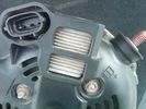
Alternator Plug and B+ terminal918 viewsPictured is the rear of the older Land Rover part # YLE500190 alternator showing the shiny cooling fin of the Regitar VRH2005-142 regulator under.
The first pin in the far left side of the connector is numbered #1 in the LR electrical wiring diagrams and is Battery Voltage Sensing (BVS); the middle pin, #2 receives a Pulse Width Modulated (PWM) signal from the Engine Control Module (ECM), and the right pin, #3 carries a PWM signal back to the ECM. Terminal Pin #2 on the LR wiring diagrams is called Alternator Control or ALT CON; Pin #3 per LR is called Alternator Monitoring or ALT MON.
Pin #1 is similar to what in older designs used to be called A or Batt, but is now called by Denso, S, AS, or Alternator Sensing for this design. Pin #1 also provides power to excite the alternator at startup until the PWM instructions over ride the battery voltage info. Land Rover calls the electronics under the pins a Smart Regulator, ironic, as it has to follow orders from the ECM rather than give the orders - new age thinking I guess. This is different from older design internal regulators that look at just the battery or the electrical buss voltage and then decides itself what to do.
It is almost like we are back to the external regulator designs of old, except that the ECM may decide that instead of telling the alternator to make more power, to load shed, and hence shut down the heated windscreen, seats, or whatever other electrical loads it decides are appropriate. My view is that the "smarts" are in the ECM and that the "regulator" should be regarded if not dumb, then as being a slave to the ECM.
|
|

how to install Altox WBUS-4 in engine room on Discovery 395 viewsthis is to show how to install the Altox WBUS-4 in engine room of a Discovery 3, but i would recommend to install it inside car in footwell, see other PDF in this album
|
|
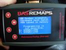
BAS remap interface after dealer software update287 viewsBAS remap interface after dealer software update,This is what you will be presented with after the dealer updates your cars engine software.
This is no problem IF you have returned the car to standard before the dealer visit.
When faced with this screen it will show you tht the dealer has changed the software and NOT let you put the BAS mapping back on your car because of the differences.
|
|
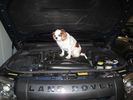
Always start with removing the dog from the engine compartment55 views
|
|

77 views
|
|
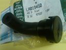
Breather Cap part # LR0194501540 viewsThis is the replacement breather cap as manufactured by the Gore Tex people, (Gore), for the engine compartment end of the front differential breather line.
You can with some difficulty, both blow and suck thru the breather filter material. The Gore Tex filter material has what are called hydrophobic and oleophobic properties. This means the filter material keeps oil in and water out, while at the same time, allowing air pressure to slowly equalize, (air permeable). Additionally, the transfer of dust, salt, and road debris is inhibited.
|
|

Nice looking piece of engineering 53 views
|
|
Thread upload16 viewsImage uploaded in thread 137794
|
|
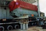
Grand Cayman97 viewsA 120tonnes Diesel Engine being skidded from road transport vehicle to final position in Grand Cayman,we were responsible from Stockport up to final job site,including al shipping and transportation.
|
|
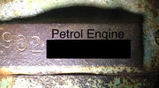
P engine number 3 views
|
|
Thread upload19 viewsImage uploaded in thread 152682
|
|
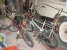
Chopper with an Engine146 views
|
|

V8 Supercharged engine62 views
|
|
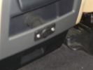
Auxiliary power sockets - TracTronics, Australia382 viewsA complete kit including two outlets, wiring etc connected to auxiliary Optima Blue top battery using their very effective SC40 split charge relay. One outlet between rear and front seats, and 2nd alongside loadspace 12v outlet, enables fridge to run when engine is not running, without affecting start capacity or vehicle functions.
|
|
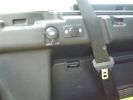
TracTronics loadspace power socket 382 viewsThe 2nd power socket fitted alongside the original in the loadspace runs off the auxiliary Optima Bluetop battery to run a fridge when engine is not running. No more starting worries!
|
|

Citroen Manual26 views
|
|

22 views
|
|

Thread upload43 viewsImage uploaded in thread 164028
|
|
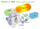
Compressed Air Engine Schematic36 views
|
|
CounterAct Power Supply mounted 246 viewsPicture is blurred, however power supply is 3M two sided tape to the flat black plastic of the second battery compartment just under the antilock brake pipes to the fender side of the brake fluid reservoir. The white wire to the left rear coupler pad runs thru the firewall hole near the steering column. The blue wire to the right front coupler runs across and above the engine following the other wiring looms that cross the vehicle.
|
|
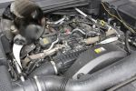
Engine Cover Removed901 viewsView of the engine before blanking off the EGRs. The inset sort of shows one of the EGR valve/pipe flange securing bolts. The EGR valves are not easy to get at!
|
|

Description of operation - Engine cooling15 views
|
|

056232 viewsP0562 SYSTEM VOLTAGE (ENGINE SIDE) TOO LOW
|
|
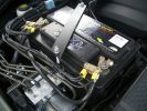
2nd battery in engine bay. Look under the rigid brake lines to see the solenoid438 views
|
|
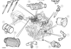
D3_Engine_Control_Sensors_Air_Charge_Temp_Sensor26 views
|
|
Thread upload27 viewsImage uploaded in thread 153207
|
|

Engine Coolant Sensor111 views
|
|

LR4 - Engine Cooling - V8 5.0L Petrol26 viewsEngine Cooling - V8 5.0L Petrol
|
|
Thread upload8 viewsImage uploaded in thread 203132
|
|

next D5 muon engine159 views
|
|

Cooling System - Description and Operation 4.0L and 4.4L petrol engines 5 pages1028 viewsThis is a 5 page pdf that provides some insight into how the coolant flows thru all the hoses. Of interest is the paragraph,(page 3/5), that attempts to explain how and why the thermostat is designed to open at different engine operating temperatures - in brief, the reason for the spaghetti tangle of small hoses on the top of the engine.
There is also reference to an engine oil cooler that I gather cools something I think related to a supercharger, if fitted.
|
|

Engine - Description12 views
|
|

Diesel - Ethanol co-fuel Paper114 viewsInteresting read - one local authority (Redland Shire Council) has 180 vehicles on trial and is pleased with the results; more power, engines run cooler; lower emissions including reduced smoke and it is a renewable resource to boot!
|
|
Thread upload19 viewsImage uploaded in thread 155591
|
|
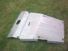
99 viewsASFIR engine guard and skid plate
|
|

Main secondary gear repair bush491 viewsPDF file of engineering drawing of bush turned up to repair the main secondary gear in the EPB gearbox.
Old gear has to be drilled out accurately to the external diameter of the bushing shaft.
|
|
Thread upload21 viewsImage uploaded in thread 162599
|
|

4.4 V8 Engine2573 views
|
|
Thread upload15 viewsImage uploaded in thread 139047
|
|
![Filename=DisplayImage[3].jpg
Filesize=30KB
Dimensions=500x331
Date added=21.Jun 2006 DisplayImage[3].jpg](albums/userpics/10853/thumb_DisplayImage%5B3%5D.jpg)
Freelander2 Engine?192 views
|
|
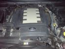
Land Rover logo on the engine cover298 views
|
|

27litre RR Meteor engined Rover SD184 views
|
|
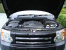
Engine836 viewsand other bits of plastic
|
|
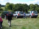
Gentlemen, start your engines!376 views
|
|

IBS contoller showing battery condition (engine off)217 views
|
|
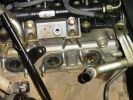
Dead engine135 viewsExhaust ports showing where leaked coolant has gone into the manifold and filled the turbo
|
|
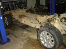
Chassis172 viewsChassis with body lifted off, and engine out
|
|
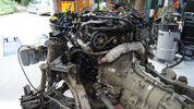
Engine and Transmission19 views
|
|
New engine138 viewsReplacement engine, reconditioned unit via Land Rover Australia, circa $6k
|
|

Engine Included16 views
|
|
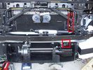
Installed winch with hydraulic hoses178 viewsThe hydraulic hoses are stiff, so I had to run them up the side of the radiator (can just see inside red boxes) to near the top of the radiator, then back down inside the engine compartment, then underneath the engine (behind the radiator) to the D4's power steering rack, where the hoses become metal. This hose routing may not be possible if the fuel-burning heater is in place (we don't have those in Aust and the space allowed room for my hands to bend and run the hoses without kinking).
|
|
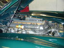
46 viewsEngine bay.
|
|
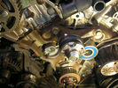
126 viewsEngine Timing
|
|
DSC_003221 viewsCan Bus Engine Bay (no.2)
|
|
DSC_003320 viewsCan Bus Wiring Engine Bay
|
|

Diagnosis and testing - engine cooling10 views
|
|

Earth Strap Fix6 viewsHow to fix the corroded engine to chassis earth strap
|
|
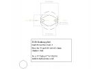
Drawing of Euro III engine EGR blanking plate213 views
|
|

electronic engine controls43 views
|
|

Electronic_Engine_Controls.pdf43 views
|
|

4.4 V8 Description102 views
|
|

conversion130 views
|
|
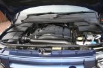
144 views
|
|

Engine Description TDV685 views
|
|
137 views
|
|

283 views
|
|

215 views
|
|

201 views
|
|

195 views
|
|

184 views
|
|

218 views
|
|

181 views
|
|

199 views
|
|

178 views
|
|

Engine off8 viewsEngine off
|
|
28 views
|
|
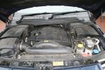
Location of oil filter on 2006 TDV6352 viewsLocation of oil filter on 2006 TDV6
|
|

181 views
|
|
108 views
|
|

36 views
|
|

Thread upload17 viewsImage uploaded in thread 153207
|
|
Thread upload1 viewsImage uploaded in new thread
|
|

Thread upload0 viewsImage uploaded in new thread
|
|

Thread upload6 viewsImage uploaded in thread 40682
|
|

Thread upload7 viewsImage uploaded in new thread
|
|

Thread upload3 viewsImage uploaded in new thread
|
|

Thread upload5 viewsImage uploaded in thread 194430
|
|

Thread upload0 viewsImage uploaded in new thread
|
|

Thread upload2 viewsImage uploaded in new thread
|
|

Thread upload19 viewsImage uploaded in thread 150996
|
|
16 views
|
|
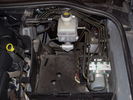
Spare Battery Bay with unknown box near the dipstick38 views
|
|
Thread upload11 viewsImage uploaded in thread 140879
|
|

Thread upload9 viewsImage uploaded in thread 140879
|
|

Thread upload9 viewsImage uploaded in thread 140879
|
|

Thread upload42 viewsImage uploaded in new thread
|
|

Thread upload0 viewsImage uploaded in thread 189220
|
|

34 views
|
|
Thread upload3 viewsImage uploaded in thread 207823
|
|
Thread upload4 viewsImage uploaded in thread 207823
|
|
Thread upload4 viewsImage uploaded in thread 207823
|
|

Engine Banks39 viewsEngine Banks
|
|
Thread upload29 viewsImage uploaded in new thread
|
|

Thread upload30 viewsImage uploaded in thread 153207
|
|
Thread upload4 viewsImage uploaded in thread 180648
|
|

Thread upload10 viewsImage uploaded in thread 171906
|
|
Thread upload2 viewsImage uploaded in new thread
|
|
8 views
|
|

Thread upload4 viewsImage uploaded in thread 189350
|
|
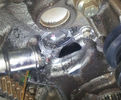
81 viewsEngine Casting
|
|
Thread upload0 viewsImage uploaded in thread 172568
|
|
Thread upload6 viewsImage uploaded in thread 115832
|
|
Thread upload4 viewsImage uploaded in thread 115832
|
|
Thread upload4 viewsImage uploaded in thread 115832
|
|

2.7 cooling5 views
|
|
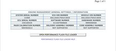
Thread upload40 viewsImage uploaded in new thread
|
|

Thread upload3 viewsImage uploaded in thread 199339
|
|
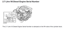
TDV6 engine id36 viewsTDV6 engine id
|
|
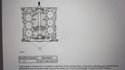
Thread upload17 viewsImage uploaded in thread 199883
|
|
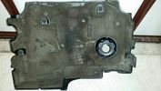
Thread upload9 viewsImage uploaded in new thread
|
|
Thread upload10 viewsImage uploaded in new thread
|
|

Thread upload8 viewsImage uploaded in thread 128758
|
|
Thread upload12 viewsImage uploaded in thread 159832
|
|

Thread upload23 viewsImage uploaded in thread 159240
|
|
Thread upload26 viewsImage uploaded in thread 100709
|
|
Thread upload28 viewsImage uploaded in thread 100709
|
|
Thread upload25 viewsImage uploaded in thread 100709
|
|

Thread upload14 viewsImage uploaded in thread 158296
|
|
Thread upload2 viewsImage uploaded in new thread
|
|

26 views
|
|
Thread upload1 viewsImage uploaded in thread 165223
|
|

D Engine Number3 views
|
|
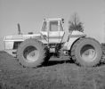
My favourite 4wd , spent thousands of hours farming with this. Sold it in immaculate condition.129 viewsVery well engineered Tractor. 16 Fwd grs,4 speed P/Shift weighed 1800 lb alone (if I remember correctly), 4 equall sized clutch packs, alternates 2 lay shafts with clutch packs, dry sump. no master clutch or TQ/C,Cat 3306DTA. 1 of 12 in Australia.
|
|

55 viewsfbh fuse location in engine bay fuse box
|
|

Fluid, Filter/Pan Combo removal and install5979 viewsThese are the LR instructions re removal and install of the plastic pan/filter combo for the ZF 6HP26X transmission on the 4.4L petrol V8 LR3.
The instructions tend to ignore the reason you have to lift the right hand side of the engine about 40 mm. This is because of a frame cross member that interferes with dropping down of the plastic pan. The real problem is a vertical "oil filter spout" that rises out of the filter/pan combo up into the transmission. The spout is the suction pipe for filtered transmission oil back up into the tranny.
On the metal pan versions, the filter is separate from the pan, hence the filter remains with the tranny when the metal pan is dropped. The filter is then removed or installed independent of the metal pan, hence with the metal pan, there is no need to lift the engine.
If one is removing the plastic pan so as to install the metal pan, then some do not lift the engine but just drop the plastic pan enough to gain access to saw off the vertical plastic spout - it is a one time procedure.
Be aware however that the metal pan uses a flat gasket and the plastic pan uses a O ring like perimeter gasket that sits in a half round groove in the tranny casing. Also the metal pan uses 21 shorter torx M6x22.5 metric cap screws for the perimeter bolts. The plastic pan uses longer M6x28.5 torx metric cap screws.
|
|

Ford News Cover Story May 2006218 viewsFord News is a monthly publication (aka propaganda!) magazine, given to all Ford workers. This months issue has a lead article about the TDV8. Thought it might be of interest.
|
|
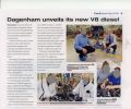
V8 Story254 viewsHere is the article about \'Job 1\' for the new TDV8, hopefully destined for the Discovery 3!!
|
|
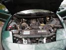
46 viewsCorvette 5.7 litre engine with 6 speed (7 if one counts reverse) manual trans. Car was custom built for me at the factory in Canada.
|
|

Breather Hose exploded view.1231 viewsThis pdf shows the exploded view of the breather hose from the front differential to the engine compartment. The breather hose part number is TAP500081 and is identified as 4A058 in the drawing.
|
|

Thread upload2 viewsImage uploaded in thread 198799
|
|

Thread upload4 viewsImage uploaded in thread 202370
|
|

GX107 and Webasto 1533 timer mounted in engine bay7 views
|
|
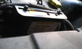
Solenoid not yet engaged18 viewsWith the engine running, the counter in the solenoid starts running and the green light blinks until the timer hits 5 minutes.
|
|
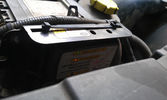
Solenoid engaged15 viewsAfter the engine's running for 5 minutes, the solenoid gets engaged and starts charging the auxiliary battery.
|
|
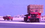
109 shepherding a Mirrlees Diesel Engine Delivery to Dubai Power Station74 views
|
|
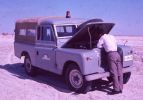
End of the line at Ras Al Khaimar72 viewsI am led to believe that this example was left overnight on the beach broken down - by morning the natives had stripped every last piece of usefull equipment out of it, engine and all and dragged it across the creek back to their village
|
|

After new engine and new wheels39 views
|
|
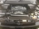
Engine11 views
|
|

Engine - Image9 views
|
|
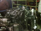
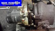
Blown Turbo127 viewsThe Turbo blew on this D3 with only 30,000k Its a 2007 model and the easiest way to get at the engine was to remove the body which is attached to the body by 10 bolts
|
|
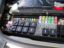
Picture of the engine compartment fuse panel5778 viewsEngine compartment fuse panel located near the battery. This is where F3E, (5 amp), F26E, (20 amp), Fuseable link 10E, (60 amp) and Relay 7E, the now upgraded 70 amp air compressor motor relay, part number YWB500220, (E is for Engine compartment fuse box), are all located. Fuse F35P, (5 amp), is inside the Passenger compartment behind the lower glove box door.
To keep the suspension from going down to the stops when driving, (or parked), it appears that it is only really necessary to remove F26E to depower the exhaust valve and generally keep all the valve block solenoid valves in a closed position trapping whatever air is within the air springs. F3E gets its power thru F26E, so when F26E is removed, the F3E circuit is automatically de-powered. F35P is more interesting in that battery power goes thru the ignition switch and F35P and then into the air suspension control unit. Apparently however, if F26E is removed, removing the F35P is not needed even when the engine is running.
With all fuses still in, if you have a problem, in practice, ideally, the compressor still works and will raise the 3 to an appropriate height. If so, one can then shut the engine off and allow the computers to go to sleep and then you remove the fuse(s). In actual practice, it seems that one need only pull the F26E fuse and can do so with the engine running. All the same, one might consider that the 3 is first a mobile computer, and secondly a 4x4. Computers prefer to go to sleep before the plug is pulled on them, however given that F26E circuit is always alive, then the computer never sleeps. With the fuse(s) pulled, and if you are still up, you can now be a 4x4 instead of a low rider. The whole purpose of the fuse pulling exercise is to depower the one and only system exhaust valve that is physically located within the compressor unit, (to keep it from opening), and secondarily to keep closed the four air spring solenoids within the block valves. This also shuts the air compressor down and stops the air compressor from making air even if the compressor is still good. That is why you initially need the fuse(s) in to allow the compressor to make air if it can.
|
|
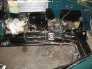
47 viewsEngine bay before rebuilt engine refitted in the summer of 2005
|
|
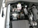
D4 Engine Bay143 views
|
|
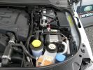
D4 Engine Bay158 views
|
|
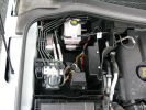
D4 Engine Bay145 views
|
|
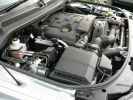
D4 Engine Bay145 views
|
|
D4 Engine Bay151 views
|
|

50 viewsRebuilt engine fitted August 2005
|
|
Dead Engine 431 views
|
|
Dead Engine 332 views
|
|
Dead Engine 236 views
|
|
Dead Engine 136 views
|
|

Cable routing in engine bay29 views
|
|
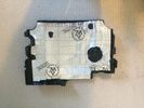
engine foam10 views
|
|

Fuel pressure at startup1 viewsFuel pressure starts at about 0.3 bar when ignition is on and lift pump is priming - then it goes off the scale - engine starts but it is not as smooth as normal
|
|

Northampton Services AA breakdown61 viewsAll the warning lights and messages, total loss of power (though engine still running).
|
|
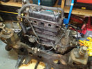
engine and sub frame out12 views
|
|
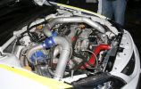
Scooby Engine51 views
|
|
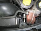
engine bay58 views
|
|
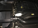
5 viewsBlown turbo hose causing the engine to cut out every time you try and over take or climb a hill. Have a new Samco kit to go on at some point.
My super bodge works a treat.
|
|

Engine 21 viewsThe remains of my 3.0ltr
|
|
engine255 views
|
|
engine 158 views
|
|
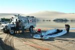
Inflating the boat at Foz180 viewsBruce had 2 Gemini inflatables on top of the Defender, with 2 engines in the rear compartment. Inflating the boats took about 30 minutes. The plan was to cross the Cunene and greet the miners on the Namibian side, which is where the Outside Edge expedition had left off a couple of weeks prior - they couldn\'t cross the Cunene in Land Rovers, so they had to go around - a detour of some 2000km
|
|
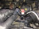
EGR replacement13 viewsWhile doing stuff on the engine. Good idea to clean yer MAF. Brake cleaner and air used to get it clean again
|
|

This is what your engine eats when the egr valves are functional20 views
|
|
prototype jcb diesel engine 185 views
|
|
prototype jcb diesel engine 175 views
|
|

Jeep Commander, Rocky Mountain National Park, Colorado156 viewsA 5.7 litre V8 330bhp POS!
When you plant the throttle, engine noise just gets louder, nothing else happens!
|
|

The rebuid data missing from Land Rover Workshop Manual39 viewsFrom PSA
- Engine Type
- Matching Bearing Sheels
- Thightening Torques Nm
|
|

Thread upload7 viewsImage uploaded in thread 199822
|
|

L319_Discovery_4_SDV6_3L_Diesel_EU5_OBD_Engine_Management_System28 viewsL319_Discovery_4_SDV6_3L_Diesel_EU5_OBD_Engine_Management_System
|
|
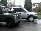
Old and New660 views1966 Series 2a (known as Betsy) Rebuilt by myself summer 2003 onto a brand new galvanised cha ssis. Also rebuilt the engine myself winter 2004.
2004 Discovery 3 TDV6 HSE
|
|

26 viewsLION 2.7 TDV6 TIGHTENING TORQUES
|
|

LR Electric Trailer Brake C2590 Female Connector606 viewsThis female connector, C2590, located up above and near the brake pedal is for the Trailer Electric Brake Controller hookup.
The Black wire in the bottom right is pin #3, the ground. The Blue wire to the left is pin #6, the Trailer Brake Controller output going to the rear trailer socket.
The White #4 wire is the 30 amp fusible link, (Link 6E in the engine compartment junction box), for the Brake Controller 12VDC power feed from the battery. Note that this would make a pretty good power source for CB radios and the like if no electric trailer brakes were required.
Pin #5 is a Green wire from the stop lamp switch, (the control input for the Brake Controller).
This plug is standard on all NAS (LR3) vehicles, but unlikely to be found on the D3 spec units.
|
|
Thread upload3 viewsImage uploaded in thread 206152
|
|
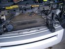
19mm wiring loom in trough behind bumper and in front of rad792 viewsThe 19mm wiring loom is large enough that a maximum of six 6mm air lines can be fished thru as required. The loom runs from the FASKIT panel located in the engine compartment behind the left front headlight, down and across in front of the rad and then down to the front axle valve block located behind and below the right fog light.
|
|
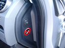
Air Suspension ECU Fuse 35P cut off switch.3820 viewsThis shows the SPST rocker switch mounted in the blank plate installed in lieu of a manual passenger side air bag shut down switch - now automatic via passenger seat pressure switch. Fuse 35P (5 amps) is located in the interior fuse box behind the lower glove box and protects the ignition power supply to the Air Suspension ECU. When the SPST switch is moved to the OFF position, the RAISE /LOWER switch on the centre console is not powered, and hence does not function. As such, some signals from the wheel height sensors and CPU are ignored. By itself however, removing F35P will probably not stop the 3 from self dropping, particularly after the engine is turned off.
Fuse F3E, (5 amps), located in the engine bay fuse box by the starting battery protects the circuit that provides feedback to the Air System ECU indicating that the Compressor Relay has successfully operated and that the Air Compressor is or should be operational, can also be removed, (but is probably not totally necessary), as it gets its power thru F26E. Hence Fuse F26E, (20 amp), also located in the engine compartment fuse box is the fuse that must be removed. This fuse protects the circuit that provides full time battery power to the Air System ECU. When in place, current thru the fuse powers the periodic re-levelling action, (usually lowering a bit with that brief air release noise), that often occurs when the vehicle is parked and the engine is off.
Removing F26E fuse will stop the auto levelling action and also inhibit any other down to the stops signals, (engine running or not). When F26E is removed, no power can flow thru to F3E, hence removing F3E is more for insurance than an absolute requirement. The same with F35P, removing F26E removes primary full time power from the Air Suspension ECU, and hence removing the F35P fuse should not really be required either as long as F26E has been removed.
|
|

Battery Maintainer pigtail sticking out of Grill726 viewsThis is all you see when everything is put back together - just the pigtail and Weather Pack blanking plug. Most often, I have it all tucked back behind the grill.
In winter, there may be a second cord hanging out as well - the 120 VAC power cord for the engine block heater, a tea kettle like element inserted in the engine block. NAS petrol V8's do not have the Fuel Burning Heater, (FBH), installed, but instead in cold area markets have the block heater element assembly available as a dealer installed option. There is an argument to say that the heating element is factory installed in all cold climate V8 gasoline engines, however the appropriate power cord is not. If true, this means that all one needs to purchase is the area specific power cord and plugging in / attachment to the engine block located block heater.
As such, you will often see a conventional 120VAC three prong power plug hanging loose out of the grill of most vehicles here in the wintertime. In summer, most drivers tuck the plug back behind the grill as it is no beauty mark.
|
|
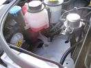
Empty space in NAS LR3 for location of FASKIT panel599 viewsThe empty space is available as the North America Spec gasoline engine LR3's do not have the Fuel Burning Heater installed. The air lines from the four air springs and the air tank will appear to rise up from under the headlight assembly. The lines to the front block valve assembly located behind the front right fog light will sort of run within the bumper across the front of the radiator down into behind the righthand fog light. The rear lines somewhat follow the path of the existing air feed line from the front valve assembly to compressor. Rather than be located between the left front fender liner and left metal wing however, the four lines will feed thru the empty wing space inside and above the wheel well arch and exit down by the left front mud flap. From there, the lines run along the left frame member above the air tank and then parallel the frame over top the compressor to the top of the rear left air spring where the rear air block valve assembly is located.
|
|

Wheel cut thru definitions and specs898 viewsNote the location of REAR SPACING and also OFFSET; probably two of the most important dimensions and not always understood as related to wheel size and relationship to the brake components.
For the 3, Rear Spacing is approximately 6.5 inches or 165 mm for a nominal 8" rim. Offset is 53P or 53mm Positive, which means the distance from the machined hub flat mounting surface to the rim's true centreline is 53 mm in the outboard direction. (The rim illustrated has a negative offset.)
As Positive offset increases, this means the wheel wraps around the disc brake mechanism more deeply, and hence the more the wheel would cover the brake parts. This is why most 18" wheels will not fit with the larger Brembo "supercharged engine" brake calipers.
Pitch circle diameter is 120mm; Pattern is 5 lug, and the tyre load rating is 112 with a recommended tyre speed rating of H or higher along with the XL load rating. For the 3, the stock tyre diameter is about 30 inches. The 255/60/18 or 255/55/19 OEM tyre outside diameter is 30.04 inches; Wheel lug torque is from 130 to 150 Nm or 96 to 110 lbf-ft and the lug nut hex socket size is 22mm.
Max Load High Speed Driving Tyre pressures are Front, 33 psig, (230 Kpa) and Rear, 42 psig, (290 Kpa).
The OEM rims are rated at 940 kgs, the highest that LR makes, hence while rims from other Land Rover products may physically fit, the odds are they are under rated in a weight sense.
|
|

LR3 TDV6 RRS TDV8 Engine Pre-heating Operating Instructions - Appendix343 viewsThis is the instructions you get with the LR original Webasto timer kit
|
|

LR3 AJV8 block heater location639 viewsThis 1 page pdf shows the screw in block heater location as related to the lower left side of the engine block.
|
|

LR3 Denso Alternator YLE500390 pulley view819 viewsNote the DENSO sticker on the side. Denso calls their nominal 150 amp 12 Volt alternator an SC2 design. SC means Segment Conductor which apparently increase the winding density of the stator coil, hence yielding a physically smaller lighter alternator for a given output. I presume the 2 means the second try at getting it right. A Denso part number is 4280003690 for the alternator, (there are others, as below).
Rotation is clockwise and the 54mm diameter pulley has 6 grooves (PV6x54). Count the pulley grooves on both the one you remove and your new one - some replacement alternators seem to ship with 5 or 7 grooves so you might be swapping pulleys.
A previous LR part number was YLE500190 for the older variation of the newer YLE500390 unit.
An additional part number for a factory rebuilt is Nippon Denso 210-0569 for the petrol V8 alternator. Other Nippon Denso numbers include 104210-3690 and 104210-3691. The Lester number is 11206 which relates to another Denso number of 290-5287. WAI uses 11206N.
From 2006 to 2009, the internal regulator is a Transpo IN6349 and of the B circuit type if it can be said that applies to PWM, (Pulse Width Modulated), regulators.
The "regulator" inside the alternator is therefore really not a regulator in the old sense of the term but instead an instruction receiver from the ECM that translates Pulse Width Modulated (PWM) signals into a form that the alternator understands – digital like signals from the Engine Control Module(ECM) into analogue like signals that the windings understand.
|
|

Engine and Transmission Electronic Controls Wiring Diagram996 viewsThis 20 page pdf shows the wiring for the electronic controls for the engine, transmission and transfer case.
|
|
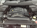
LR3_engine_bay26 views
|
|

Horn Wiring Circuit LR3578 viewsThe is the wiring diagram for the dual horn circuit.
The Horn Relay, (R133), is not a big black thing hidden somewhere but instead what is called a FET, (and it is hidden)!
This is a Field Effect Transistor that is built into the circuit board that is mounted to the back of the fuse box that is located behind the lower glove box door on the passenger side of the 3. The related 15 amp fuse, 12P, is mounted in this fuse box and is often called F12P, where F is for fuse, and P is for Passenger compartment.
This is to help differentiate from another fuse and relay box, (the usual kind), that is located beside the starting battery in the Engine compartment. FxxE is often used in the naming of those fuses.
|
|

Stop Light Lamp Circuit pdf2491 viewsThis pdf shows the brake light circuit for the NAS LR3.
Note that power for the brake light bulbs can come either thru the brake light switch power feed /contacts plus also from the Hill Decent Control, (HDC), system relay located within the Central Junction Box, (CJB) - yes two separate sources of power for the brake light bulbs. This would tend to explain how a brake light circuit concern shows up as a hill decent fault message; also why lesser vehicles without hill decent braking mechanisms, (HDC), never display this sort problem when a brake light bulb or switch acts up. You never have a problem related to a system that does not exist.
Additional evidence of the relationship of the HDC and the tail light circuit is demonstrated by when the HDC actually acts to slow the 3 down, the brake lights automatically illuminate even if the slowing action was merely retarding the engine speed or shifting to a lower gear, (in other words, no foot on the brake pedal).
There is also a tie in to the Cruise Control and hence a failing brake light switch can affect cruise operation or just create false Cruise Control messages. To further complicate the issue, while there are no messages generated, operation of the radiator electro viscous fan can also be negatively affected by the fouled set of secondary contacts within the brake light switch. This is all because the NC contacts within the brake switch send misleading messages to the ECU.
While the ground wire design is similar to other vehicles, note the grounds for the brake light filament and the reverse light filament are common on each side. That means that if one has a non functioning brake light on one side, the reverse light may not also work or that some problem with the reverse lights could back feed into the brake lights. This situation while unusual, can result when grounds are corroded probably due to swimming in rivers and creeks or just routine driving in a marine environment.
|
|

Thread upload15 viewsImage uploaded in thread 167285
|
|

Heated Windscreen Wiring Diagram408 viewsThis single page pdf is the heated windscreen wiring diagram. You can rotate the view by right clicking on the pdf and of course it can be printed out as well.
Relay R208 in the pdf is relay R9 in the Engine Compartment fuse box. Note both 30 amps fuses, F15E and F18E, also located in the Engine Compartment fuse box. If one side of your windscreen does not heat, the problem may be one of the two fuses.
|
|
Thread upload11 viewsImage uploaded in new thread
|
|

LTB00067 - Technical Bulletin - Chirp Noise on Engine Cold Start - Repair Procedure90 views
|
|

LTB00119 - Technical Bulletin - Remove Install Engine and Ancillaries62 views
|
|

LTB00122 - Technical Bulletin - Engine Coolant Fill Bleed Procedure93 views
|
|

LTB00125 - Technical Bulletin - 4.4L V8 Short Engine Availability61 views
|
|

LTB00133 - Technical Bulletin - Low Engine Coolant Level Switch - Lower Level Service Part Availability81 views
|
|

LTB00183 - Technical Bulletin - Aluminum Engine Components Thread Repair61 views
|
|

Thread upload47 viewsImage uploaded in new thread
|
|

43 views
|
|
16 views
|
|
Thread upload7 viewsImage uploaded in thread 137794
|
|

Milestone - 200k km22 viewsMight be 200 000 km but its only 58 000 on the new engine...
|
|

Bikes plus an engine= trouble83 views
|
|

NAS 7 plus 4 pin LR3 Trailer wiring, battery end. 548 viewsThis is the LR wiring diagram from the engine compartment battery location to the Electric Brake Controller connector, C2590, located under the dash near the brake pedal.
|
|

Fuel pressure at startup1 viewsFuel pressure starts at about 0.3 bar when ignition is on and lift pump is priming - then it goes off the scale - engine starts but it is not as smooth as normal
|
|
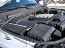
Overview of engine compartment from Main Battery side, (Passenger, LHD), looking across to Aux Battery752 viewsNote labels on main battery cover. The one you cannot read says that an auxiliary battery is installed on the other side. This is to warn service people should they wish to shut off all battery power.
The main starting battery is supposed to be of CaCa separator construction and DIN H8 or BCI Group 49 size. This means Calcium separators Wet Flooded Lead Acid, 13.9" long, 7.5" high and 6.9" wide.
On the Aux battery cover is a label saying to disconnect the blue Anderson single pole connector located under the cover by the brake reservoir. BCI Group 40R battery is small enough that the cover goes back on.
|
|

Toyota IST - almost a Love Child of MB Parents175 viewsDiscovered that this is a Toyota Ist; it comes with a 1.3 or 1.5 litre engine with the 1.5 also available in 4WD. It seems to be a popular car for customising in Japan as there are a number of sites devoted to that.
|
|
engine12 views
|
|
firewall plug run933 viewsThis is the engine side view, of where to poke the hole with a screwdriver to make a hole into the vehicle. You can barely see the edge of the hole. Note: The Rubber plug should be removed for this operation.
|
|
firewall plug run919 viewsHow to get the cable from the engine bay to the rear of the vehicle.
|
|
warn winch controller installation613 viewsremotely installed due to space limitations, and to keep the unit dry. Left Hand Drive, fitted in engine bay near washer fluid fill for reference point.
|
|
warn winch controller installation544 viewsremotely installed due to space limitations, and to keep the unit dry. Left Hand Drive, fitted in engine bay near washer fluid fill for reference point.
|
|
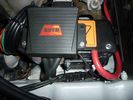
warn winch controller installation568 viewsLeft Hand Drive, fitted in engine bay near washer fluid fill for reference point.Remote control unit fitted on the box. Remotely installed due to space limitations, and to keep the unit dry.
https://www.facebook.com/DifferentialPartsUS
|
|
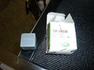
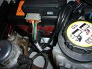
Relay Change246 viewsYWB500220 electrical, fuse & relay, relay ENGINE COMPARTMENT, 70 amp 1
|
|
Relay Change379 viewsYWB500220 electrical, fuse & relay, relay ENGINE COMPARTMENT, 70 amp 1
|
|
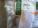
LR020590 KIT - COMPRESSOR 1481 viewsThere are 4 main parts you can get besides a whole compressor. This is the one with only a spring, o-ring and rubber valve.
YWB500220 electrical, fuse & relay, relay ENGINE COMPARTMENT, 70 amp 1
LR020590 KIT - COMPRESSOR 1
JPO500010 KIT - COMPRESSOR 1
VUB504700 - Dehydrator PARTS
|
|
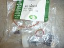
JPO500010 KIT - COMPRESSOR 1437 viewsThere are 4 main parts you can get besides a whole compressor. This is the one with more bits.
YWB500220 electrical, fuse & relay, relay ENGINE COMPARTMENT, 70 amp 1
LR020590 KIT - COMPRESSOR 1
JPO500010 KIT - COMPRESSOR 1
VUB504700 - Dehydrator PARTS
|
|
Thread upload0 viewsImage uploaded in new thread
|
|
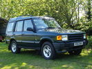
Second Discovery9 viewsMy second 300Tdi Disco. Had an oddly vibration-prone engine.
|
|
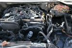
326 viewsthe fire, though pretty bad had not damaged the top of the engine or the injectors etc
|
|
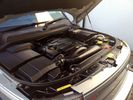
Clean Engine39 views
|
|
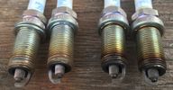
spark plugs, right ones are abnormal ?11 viewsthat is not LR engine, that Jeep's Hemi.
|
|

Powerchip Australia - TDV6 Gold Upgrade201 viewsFrom an Aussie company that has advertised in motoring magazines for the last 8-10 years that I can recall. The cost is $AUD1491 (~596GBP). Does anyone know anything about them?
Booklet shows engine chart comparing standard with Powerchip's Gold 'chip'.
|
|

2004 Citroen C8191 viewsMy second 7 seat motor - another big french tank with plastic bodywork in silver, complete with shopping trolley handle on the roof. A 2 ton motore with a 2.0l petrol engine mated to a 4 speed auto box - not good for performance!
|
|

new engine with most of new bits bolted back on 25 views
|
|
Thread upload19 viewsImage uploaded in new thread
|
|
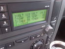
Voltage Display Page Radio Head Unit 118 14.2840 viewsThis shows the voltage/temperature/timer display page within the 6CD-465 radio head. There is a second file within this album, a doc file, that outlines the procedure to access the diagnostics.
The 14.1 volts number was the approximate vehicle system voltage with the engine running; the 118 number infers 11.8 volts which is the low power infotainment system shutdown cutoff voltage. The factory default setting is 135 or about 13.5 volts. By holding the keypad 1 button down, the 3 digit volts numbers will decrease 001 at a time until the keypad 1 button is released. Decreasing the number from 135 to some lower number should increase the time the system will remain on with the engine off.
The TEMP numbers refer to Fuel Burning Heater, (FBH), temperature values. 85 is apparently a high limit and 46 was the number when the jpg was taken. This number varies and given that there is no diesel fueled FBH in our NAS petrol engine vehicles, what the value refers to is unclear. The TIMER numbers also relate to the diesel fuel burning engine heater and perhaps make more sense being 00.
|
|
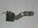
Radio Noise Suppression Capacitor NNW502820699 viewsThis is the radio noise suppression capacitor, part number LR020488 (previous NNW502820), that is mounted underneath and near the transmission. It is powered by fuse 10 amp F30E in the engine compartment. If F30E blows, (the fuse that also powers the transmission ECU), the problem is probably caused by the failed capacitor, not the ECU. A quick fix is just to disconnect the capacitor and replace the fuse as nothing bad seems to immediately result.
The above radio noise capacitor is not to be confused with LR004160, the ignition noise capacitor which is located under the black plastic engine cover on the right hand side above the air intake towards the rear of the engine.
The ignition capacitor is held on with a single 8mm bolt and a three wire electrical connector. Replacing the ignition capacitor as a routine maintenance prevention action at 100,000 miles, 160,000 km), has merit. It is a do it yourself kind of thing and easier to get at than the radio capacitor underneath.
|
|
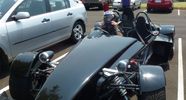
45 viewsRCR Superlite Razor - front view. Mitsu Evo turboed engine. No other details known but very impressive 'toy'.
|
|

Transpo pdf explaining the operation of Ford PWM regulators624 viewsThe 4 page pdf produced by WAI-Transpo explains the operation of the Pulse Width Modulated regulators located within the alternators on our 3's. Of note, the pdf states that certain of the Ford PWM regulators do not meet Ford spec.
The pdf explains the function of all the terminals and the apparent advantages of the PWM style over previous designs. Note that Ford calls their "engine computer" a PCM, (Power Control Module), whereas Land Rover, an ECM, (Engine Control Module).
|
|
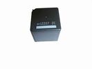
Front Blower R16 relay, part number YWB500060481 viewsThis is the front fan relay located in the engine compartment fuse box. It should be replaced and installed new when a new fan is installed.
|
|
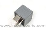
Air Compressor 70 amp replacement relay1393 viewsThere is a software update, 09 April 2010, LTB00270, for the compressor which reduces the shut down pressure to about 205 psig (14 bar). The update is usually done when changing to a new compressor and also includes replacing the R7 relay in the engine compartment fuse box, 07 DEC 2010 LTB00331.
The newer grey case coloured relay, part # YWB500220, shows to be rated at 70 amps, (the relay, not the compressor), however the previous black case coloured relay also indicates 70 amps.
Both the new and replaced relay show on their wiring diagrams to have a parallel voltage spike resistor, (probably 560 ohms), across the coil terminals, #1 and #2. This means one does not just replace the relay with any four prong 70 amp ISO sized relay that one happens upon.
One presumes the grey relay is either upgraded or just being installed for good measure. The relay is common on Ford Fiesta for the seat heater relay, Ford part number 5M5T 14B 192 EA; also Volvo, part number 30765034. The Tyco part number moulded on the grey body is V23136-J4-X62.
|
|

166 views
|
|
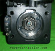
NAS 7 pin + NAS 4 pin Flat Trailer Socket308 viewsThis is the vehicle end of the NAS trailer harness that is located behind the removable plate centered within the rear bumper by the towing loop. Re the four pin flat connector, from the bottom, the exposed bare lower pin is the ground, usually the White wire on a NAS trailer. The next pin up is normally a Brown wire on a trailer and is for the Tail Lights. The third pin, normally a Yellow wire, is the left signal light; the top pin, normally a Green coloured wire, is the right signal light.
Re the round connector, from the notch in the plastic surround, clockwise, the first blade is ignition controlled +12VDC battery power, (only alive when engine running), and on the Land Rover factory harness is an Orange wire; on a NAS trailer, usually Red but perhaps a Black wire.
Next blade clockwise at 3:00 o'clock above, is the Right Turn signal light, a Green wire on the LR harness, and also on a NAS trailer.
At 5:00 o'clock, the next blade is for the Electric Brakes and is Blue on both the LR harness and on a NAS trailer.
The Ground wire is next, White on both the LR harness and on a trailer.
At 9:00 o'clock above, is the Left Turn signal, Yellow on both the LR harness and on a trailer.
The last blade to the left of the line up notch is the Tail Light circuit. On the LR harness, the wire colour is Brown with two White stripes and on a NAS trailer, Brown.
The centre pin is for the Reverse Back Up lights and is Black on the LR harness and often Purple on NAS trailer wiring but can be Black also.
Note that when the socket assembly is installed on the 3, the notch in the plastic surround is on the left - that is rotated 90 degrees anticlockwise to the picture above. In other words, When installed on the 3, the 4 pin flat connector lays horizontal and is located below the round socket.
|
|
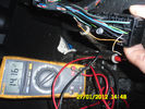
Voltage reading72 viewsHere is the voltage to the heated seat. Engine running. Did not enable heat on the hvac.Why 14v there now?
|
|

25 viewsshowing the fixed tensioner on the upper right of the engine
|
|

Thread upload4 viewsImage uploaded in thread 184496
|
|

Skid plate engine223 views
|
|

My old Seadoo RXT 291 viewsOn holiday with the ski's, St Tropez France.
My RXT on the left, supercharged & intercooled 1500cc rotax engine...aftermarket freeflow intake system by RIVA, SOLAS blueprinted prop, race sponsons, RIVA intake grate & opas system removed for less drag...estimated 230hp.
Proven 70mph (with GPS & Radar gun)
On the right is my best man's GTX Ltd. with 185hp and good for 60mph with a tail wind...
|
|

Thread upload46 viewsImage uploaded in new thread
|
|

EGR Stub Pipe866 viewsThis is one of the stub pipes that are fitted to the butterfly valve housing. When both are fitted, they meet in the middle of the housing and must present quite an obstruction to the flow of air to the engine inlet valves! Look how cruddy it is. All that muck is being fed to your engine. Ugh!
|
|

85 views
|
|
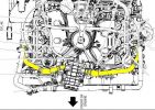
TDV6 Birds eye view of engine264 views
|
|
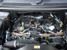
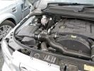
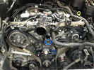
TDV6 engine bay307 views2006 TDV6 engine bay with top cover removed
|
|

tdv6104 views
|
|
Thread upload11 viewsImage uploaded in thread 199883
|
|
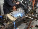
TDV8 engine+D3manual+LT230defender273 views
|
|

Unidentified ticking noise3 viewsAnyone familiar with this ticking noise? It's at the front of the engine down low. 1st heard on startup this morning.
|
|
Thread upload1 viewsImage uploaded in new thread
|
|
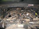
Torque tune205 viewsEngine bay view.
|
|
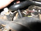
Torque tune184 viewsPosition of engine plug.
|
|

Egypt - i\'m the only one with a petrol engine158 views
|
|
Thread upload10 viewsImage uploaded in thread 128311
|
|

Thread upload12 viewsImage uploaded in thread 128311
|
|
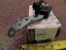
Radio Noise Filter Transmission Electronic Control Unit913 viewsThe jpg shows part number LR020488, a noise suppression capacitor located underneath on a bracket on the right side of the transmission forward of the selector shaft lever. The suppressor is connected to the transmission wiring harness and prevents solenoid operating noise affecting the audio system.
Failure of the capacitor is most often discovered as a result of either black smoke from below and or the blowing of 10 amp fuse F30E located in the engine compartment fuse box. This fuse protects the power circuit to the Transmission Engine Control Unit. When the fuse blows, the engine will still run however you have no gears, hence movement of the 3 is inhibited.
Anything over eight years in service is considered good capacitor life. If the capacitor does fail and fuse 30 blows, a quick fix is just to disconnect the capacitor and replace the fuse.
The capacitor might be missed by the DOT/FCC but the 3 does not seem to mind. With the filter disconnected, solenoid noise might be heard on some radio stations but at least the 3 would be in motion.
|
|
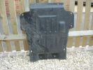
Lower engine bay tray316 viewsLower engine bay tray, 2006 Disco3 TDV6. Needs removing to gain access to sump drain plug.
|
|

Thread upload16 viewsImage uploaded in thread 135162
|
|

oh FOOK96 viewsthe range took in a heap of muddy water in through the air intake and swallowed it and spat it out its arse as steam. how the engine survived, i do not know. video coming soon. Definatly worth a look!
|
|

Thread upload1 viewsImage uploaded in thread 209375
|
|
Thread upload14 viewsImage uploaded in new thread
|
|

Varta Battery Dimension chart570 viewsThis pdf provides Varta dimensions for among others, the E12V75N, (old DIN H6 or 85605 or BCI Group 48 size). This appears to be a deep cycle battery and the choice for many re the Aux battery install as long as you are willing to grind away the angled nibs at the bottom front of the battery surround. My choice was a shallow cycle battery intended for cold weather related engine starting rather than winch use.
Note the pdf Varta batteries are all deep cycle batteries suitable for running fridges, winches etc, rather than for engine starting and hence a good Aux battery if those are the intended uses rather than engine starting.
Varta now makes a Varta G14 with AGM technology and known as a Stop Start Plus battery. It is 95Ah, CCA of 850A; length 353mm; Width 175mm; Height 790mm and is specific for these newer stop start vehicles such as some D4's. For the 3's, one is still probably better off with an H8 sized battery but of the older Wet Flooded Lead Acid type and battery caps rather than a sealed AGM.
The Land Rover part number for the recommended battery is LR033179.
|
|

Thread upload6 viewsImage uploaded in new thread
|
|

Water Pipe22 viewsTop engine to radiator water pipe chafed through on the plastic sound damper.
|
|
Thread upload10 viewsImage uploaded in new thread
|
|
Thread upload1 viewsImage uploaded in thread 187493
|
|
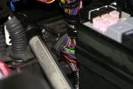
Main loom passes through bulkhead behind the engine bay fuse box next to the battery140 views
|
|
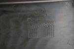
Stamp in base of right (as in drivers, RHD, left when viewed from front of engine bay) cover109 views
|
|
|
|