| Search results - "dig" |

120 viewsTaken by A Filipinski - Digigraphics.co.uk
|
|
115 viewsTaken by A Filipinski - Digigraphics.co.uk
|
|

152 viewsTaken by A Filipinski - Digigraphics.co.uk
|
|
Thankfully it\'s nearly a week old. they wanted to dig underneath my drive to install gas. Nov 5th, Bang,78 viewsNo, and i was worried about the rangerover!
|
|

116 viewsTaken by A Filipinski - Digigraphics.co.uk
|
|

119 viewsTaken by A Filipinski - Digigraphics.co.uk
|
|

134 viewsTaken by A Filipinski - Digigraphics.co.uk
|
|

141 viewsTaken by A Filipinski - Digigraphics.co.uk
|
|

149 viewsTaken by A Filipinski - Digigraphics.co.uk
|
|
158 viewsTaken by A Filipinski - Digigraphics.co.uk
|
|
148 viewsTaken by A Filipinski - Digigraphics.co.uk
|
|

164 viewsTaken by A Filipinski - Digigraphics.co.uk
|
|

Alternator and Regulator Wiring Diagrams, TDV6 and petrol V8 and V61989 viewsThis is a three page pdf that shows the alternator and regulator wiring for the petrol V6, petrol V8 and TDV6. The pdf can be either printed or by right clicking on the displayed pdf, rotated as required for viewing.
Of interest is that the regulator gets its instructions primarily from the Engine Control Module (ECM) and only secondarily from the vehicles electrical buss. The conductor from the battery thru the 5 amp fuse F20E is to provide initial power to excite the alternator at startup and then secondarily, to instruct it if the PWM signals were not available. Primary instructions to and from the ECM are thru the two other conductors via a digital like Pulse Width Modulated (PWM) signal.
If F20E, the 5 amp engine compartment fuse box fuse is blown, the red alternator light on the dash will be illuminated. This means that the alternator could be OK, but if the F20E fuse is blown, no electricity will be generated. Hence check the F20E fuse if you get a red ALT light or some indication of the alternator not working.
Regarding operation of the red ALT light on the dash, it is not the regulator within the alternator that tells the red light to illuminate, or not, but instead the ECM. This is the reason the red light does not function in the same manner as with older vehicles. With the 3, sometimes you have illumination and sometimes not depending upon what the ECM is thinking. What this means is that you can have an alternator that is failing but the red light does not illuminate as the ECM is compensating for reduced alternator output - maybe by draining the battery and or cutting back on vehicle electrical loads such as shutting off or cycling the radio amplifier or heated seats.
|
|
Thread upload5 viewsImage uploaded in new thread
|
|
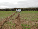
Muddy field162 viewsDid we just dig that?
|
|

Bald Seet village164 viewsDescendign a steep concrete track over gravel into the villaeg of Ballad Seet. Curious in a dry, desert country to find verdent growth of palms, and agricultural produce on well watered terraces.
|
|

100 views
|
|

G4 with trailer124 viewsTaken with digital SLR - slow shutter, narrow ap. zoom during exposure - so I\'m told - great effect just don\'t look at it for too long!
|
|

Close to the Dig Tree67 views
|
|

Dig Tree71 views
|
|
![Filename=Cura_Ponte radio_Faggeta 12-2008 22 - 28 dic 2008 - 22_m [1024x768].jpg
Filesize=321KB
Dimensions=576x768
Date added=06.Jan 2009 Cura_Ponte radio_Faggeta 12-2008 22 - 28 dic 2008 - 22_m [1024x768].jpg](albums/userpics/12685/thumb_Cura_Ponte%20radio_Faggeta%2012-2008%2022%20-%2028%20dic%202008%20-%2022_m%20%5B1024x768%5D.jpg)
My Camera moount 292 viewsIl supporto per la fotocamera digitale
|
|
![Filename=Cura_Ponte radio_Faggeta 12-2008 24 - 28 dic 2008 - 24 [1280x768].JPG
Filesize=121KB
Dimensions=1024x768
Date added=06.Jan 2009 Cura_Ponte radio_Faggeta 12-2008 24 - 28 dic 2008 - 24 [1280x768].JPG](albums/userpics/12685/thumb_Cura_Ponte%20radio_Faggeta%2012-2008%2024%20-%2028%20dic%202008%20-%2024%20%5B1280x768%5D.JPG)
My Camera moount 1100 viewsIl supporto per la fotocamera digitale
|
|
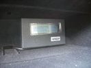
Genesis digital battery system - monitor in top glovebox323 views
|
|

96 views
|
|

The beast54 views
|
|

103 views
|
|

102 views
|
|
186 views
|
|

Papa King shows us why you never travel alone198 viewsAll of a sudden the sand became spongy, and Kingsley\'s vehicle just sunk in up to the chassis. Took the guys quite a while to dig and winch it out.
|
|
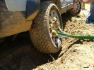
Rear wheel dig116 viewsYou can see here how much the right rear tyre has descended into the furrow we dug.
|
|
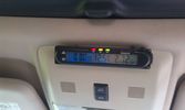
Battery check display15 viewsI mounted a digital battery display in order to see the voltage on the auxiliary battery.
There's also a thermometer which gives the inner and outer (via a side switch) values.
The display is switched on/off via another rocker switch.
|
|

LP scoped 222 viewsBy connecting a Low Amps probe to the fuel pump's voltage supply wire, you can view the pump's current waveform on a digital storage oscilloscope (DSO). The scope pattern will reveal internal wear in the brushes and commutator that may not show up in a traditional pressure or volume test.
Observing the waveform will show if the pump's amp draw is normal for the application or is high or low, and if the pump is operating at normal speed or is running slow. Problems such as a bad spot on a commutator or a short or open in the armature also will be obvious in the waveform.
A "good" electric fuel pump waveform will generally seesaw back and forth with relative consistency and minimal variation between the highs and lows. A "bad" waveform will show large or irregular drops in the pattern, with large differences between the highs and lows.
|
|

Gun Dogs don't dig..... It must have been someone else as we've had nothing to do with this....16 viewsCaught in the act
|
|

Hunt the skis188 viewsSpent about twenty minutes hunting for my skis here, after hitting a rock. Eventually found I'd been digging on the wrong track all the time!
|
|

Snowy Disco3 and digger20 views
|
|

19 viewsDigger after towing thru" snow storm
|
|

Salisbury Plain. Nov 2012248 viewsApologies for the quality, some digital cameras are better than others. The plain is very wet currently, all due to that wonderful summer we had.
|
|

Thread upload12 viewsImage uploaded in thread 157919
|
|

Part numbers for JAE connectors for the upper hatch switch. 382 viewsThis lists the JAE and Digi-Key part numbers for the electrical connectors for the hatch switch.
I contacted Japan Aviation Electronics and they directed me to Digi-Key in the USA who sell odd lots of the JAE product, odd lots meaning two pins and one connector if that is all you wish.
|
|

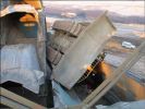
POOR LITTLE DOZER TOSSED UP ONTO THE KRUPS ARM125 views
|
|
106 views
|
|
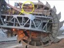
BULL DOZER TOSSED UP ONTO ARM119 views
|
|
69 views
|
|

LR3 Denso Alternator YLE500390 pulley view819 viewsNote the DENSO sticker on the side. Denso calls their nominal 150 amp 12 Volt alternator an SC2 design. SC means Segment Conductor which apparently increase the winding density of the stator coil, hence yielding a physically smaller lighter alternator for a given output. I presume the 2 means the second try at getting it right. A Denso part number is 4280003690 for the alternator, (there are others, as below).
Rotation is clockwise and the 54mm diameter pulley has 6 grooves (PV6x54). Count the pulley grooves on both the one you remove and your new one - some replacement alternators seem to ship with 5 or 7 grooves so you might be swapping pulleys.
A previous LR part number was YLE500190 for the older variation of the newer YLE500390 unit.
An additional part number for a factory rebuilt is Nippon Denso 210-0569 for the petrol V8 alternator. Other Nippon Denso numbers include 104210-3690 and 104210-3691. The Lester number is 11206 which relates to another Denso number of 290-5287. WAI uses 11206N.
From 2006 to 2009, the internal regulator is a Transpo IN6349 and of the B circuit type if it can be said that applies to PWM, (Pulse Width Modulated), regulators.
The "regulator" inside the alternator is therefore really not a regulator in the old sense of the term but instead an instruction receiver from the ECM that translates Pulse Width Modulated (PWM) signals into a form that the alternator understands – digital like signals from the Engine Control Module(ECM) into analogue like signals that the windings understand.
|
|

426 viewsDigging out the Freelander (the lady with the shovel is Minna Sillankorva, 10 times Finnish Ladies\' Rally Champion, and one of the instructors)
|
|
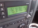
Voltage Display Page Radio Head Unit 118 14.2840 viewsThis shows the voltage/temperature/timer display page within the 6CD-465 radio head. There is a second file within this album, a doc file, that outlines the procedure to access the diagnostics.
The 14.1 volts number was the approximate vehicle system voltage with the engine running; the 118 number infers 11.8 volts which is the low power infotainment system shutdown cutoff voltage. The factory default setting is 135 or about 13.5 volts. By holding the keypad 1 button down, the 3 digit volts numbers will decrease 001 at a time until the keypad 1 button is released. Decreasing the number from 135 to some lower number should increase the time the system will remain on with the engine off.
The TEMP numbers refer to Fuel Burning Heater, (FBH), temperature values. 85 is apparently a high limit and 46 was the number when the jpg was taken. This number varies and given that there is no diesel fueled FBH in our NAS petrol engine vehicles, what the value refers to is unclear. The TIMER numbers also relate to the diesel fuel burning engine heater and perhaps make more sense being 00.
|
|
171 views
|
|
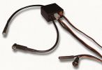
RDS Digital Thermometer240 viewsRDS Digital Thermometer
|
|
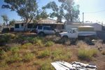
5 Star digs at Oodnadatta113 viewsThe ute in the foreground is a Datsun!!!
|
|
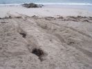
After the Big Dig!68 views
|
|
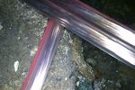
Amdeal 30ft / 10M USB Digital Microscope Cable Wire Endoscope Camera Video Recording Inspection Pipe Camera - Waterproof, 4 LED Lights27 viewsUnder XP system, can watch video directly without install software. By using our software, can take photo,record video, and save the video in the PC. Such USB microscope widely used to inspect tube, check the body, magnify stamps, coins, antiques, insects, electric circuits, machines, fabrics, food, decorations, etc. Please notice that the wire camera is designed for industrial use, not for medical use.
Camera: 1/6" VGA COMS
Pixel: VGA 300K
Resolution: 640x480,352X288,320X240,176X144,160X120
Capture Resolu
|
|
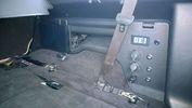
PS2 + Split charge system 10 viewsPS2 - Wireless controllers and headphones.
Split charge system with auxiliary sockets with digital voltage display
|
|
|
|