| Search results - "diagram" |

0000 LR Bluetooth dealer Kit install instructions1610 viewsThis 17 page pdf is mostly a series of pictures showing how to install the original Land Rover dealer installed Bluetooth kit for circa 2005 / 2006 three's. Also included are three wiring diagrams sheets related to the pairing code 0000 Bluetooth install.
This pdf is useful if you are now removing the 0000 kit to install the optical 2121 MOST D4 module, an easier install than the 0000 kit ever was.
|
|

Thread upload5 viewsImage uploaded in thread 171152
|
|

Thread upload15 viewsImage uploaded in thread 153386
|
|
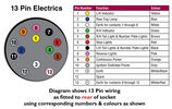
Thread upload13 viewsImage uploaded in thread 165627
|
|
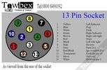
Thread upload16 viewsImage uploaded in thread 184914
|
|

Alternator and Regulator Wiring Diagrams, TDV6 and petrol V8 and V61989 viewsThis is a three page pdf that shows the alternator and regulator wiring for the petrol V6, petrol V8 and TDV6. The pdf can be either printed or by right clicking on the displayed pdf, rotated as required for viewing.
Of interest is that the regulator gets its instructions primarily from the Engine Control Module (ECM) and only secondarily from the vehicles electrical buss. The conductor from the battery thru the 5 amp fuse F20E is to provide initial power to excite the alternator at startup and then secondarily, to instruct it if the PWM signals were not available. Primary instructions to and from the ECM are thru the two other conductors via a digital like Pulse Width Modulated (PWM) signal.
If F20E, the 5 amp engine compartment fuse box fuse is blown, the red alternator light on the dash will be illuminated. This means that the alternator could be OK, but if the F20E fuse is blown, no electricity will be generated. Hence check the F20E fuse if you get a red ALT light or some indication of the alternator not working.
Regarding operation of the red ALT light on the dash, it is not the regulator within the alternator that tells the red light to illuminate, or not, but instead the ECM. This is the reason the red light does not function in the same manner as with older vehicles. With the 3, sometimes you have illumination and sometimes not depending upon what the ECM is thinking. What this means is that you can have an alternator that is failing but the red light does not illuminate as the ECM is compensating for reduced alternator output - maybe by draining the battery and or cutting back on vehicle electrical loads such as shutting off or cycling the radio amplifier or heated seats.
|
|

Entertainment System Wiring Diagrams2331 viewsThe 12 page pdf has the wiring diagrams for the low and high line "radio" and various components such as the amplifier, phone modules,NAV display, antennas and satellite radio and TV.
|
|

Exterior Lighting (Fog Lamps - Non NAS)13 viewsWiring diagram for non-NAS fog lamps
|
|

Air Suspension - parts diagram pic172 views
|
|

Air Suspension - parts diagram157 views
|
|
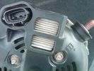
Alternator Plug and B+ terminal919 viewsPictured is the rear of the older Land Rover part # YLE500190 alternator showing the shiny cooling fin of the Regitar VRH2005-142 regulator under.
The first pin in the far left side of the connector is numbered #1 in the LR electrical wiring diagrams and is Battery Voltage Sensing (BVS); the middle pin, #2 receives a Pulse Width Modulated (PWM) signal from the Engine Control Module (ECM), and the right pin, #3 carries a PWM signal back to the ECM. Terminal Pin #2 on the LR wiring diagrams is called Alternator Control or ALT CON; Pin #3 per LR is called Alternator Monitoring or ALT MON.
Pin #1 is similar to what in older designs used to be called A or Batt, but is now called by Denso, S, AS, or Alternator Sensing for this design. Pin #1 also provides power to excite the alternator at startup until the PWM instructions over ride the battery voltage info. Land Rover calls the electronics under the pins a Smart Regulator, ironic, as it has to follow orders from the ECM rather than give the orders - new age thinking I guess. This is different from older design internal regulators that look at just the battery or the electrical buss voltage and then decides itself what to do.
It is almost like we are back to the external regulator designs of old, except that the ECM may decide that instead of telling the alternator to make more power, to load shed, and hence shut down the heated windscreen, seats, or whatever other electrical loads it decides are appropriate. My view is that the "smarts" are in the ECM and that the "regulator" should be regarded if not dumb, then as being a slave to the ECM.
|
|

ASC Wiring Diagram31 viewsASC Wiring Diagram
|
|

Kenwood v1000 AV-Controller Diagram126 views
|
|

183 views
|
|

HVAC Climate Control Wiring Diagram 62 views
|
|
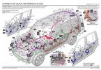
Thread upload52 viewsImage uploaded in thread 180400
|
|
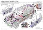
Thread upload49 viewsImage uploaded in thread 182595
|
|
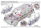
Thread upload30 viewsImage uploaded in thread 202058
|
|

Thread upload10 viewsImage uploaded in thread 104513
|
|
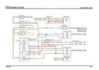
Thread upload23 viewsImage uploaded in thread 123695
|
|

Thread upload21 viewsImage uploaded in thread 142490
|
|

Thread upload19 viewsImage uploaded in thread 150396
|
|
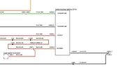
D4 Aux Lights Switch Wiring Diag80 views
|
|
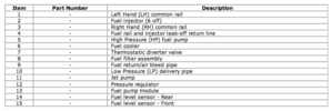
D4_Fuel_System_Diagram_Decode22 views
|
|
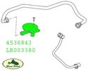
10 views
|
|

Thread upload2 viewsImage uploaded in new thread
|
|
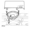
Diagram2 views
|
|

Thread upload0 viewsImage uploaded in new thread
|
|

Thread upload5 viewsImage uploaded in new thread
|
|
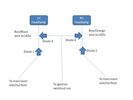
Thread upload22 viewsImage uploaded in new thread
|
|

D3 WIRING 08MY26 viewsImage uploaded in thread 185033
|
|

Thread upload9 viewsImage uploaded in thread 187892
|
|

Discovery 3 Exterior Light Wiring69 views
|
|

Thread upload12 viewsImage uploaded in thread 190934
|
|

Thread upload11 viewsImage uploaded in thread 193383
|
|

Thread upload13 viewsImage uploaded in thread 198096
|
|

Thread upload18 viewsImage uploaded in thread 147705
|
|

Thread upload7 viewsImage uploaded in thread 206759
|
|

Thread upload6 viewsImage uploaded in thread 208122
|
|

Thread upload1 viewsImage uploaded in thread 209484
|
|

D4 Headlight Wiring Diagram 1 VIN 51332638 views
|
|

D4 Headlight Wiring Diagram 2 VIN 52454535 views
|
|

5 views
|
|
Thread upload15 viewsImage uploaded in thread 158956
|
|

Thread upload12 viewsImage uploaded in thread 158956
|
|
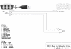
64 viewsOBD2 adapter to FBH wiring diagram, corrected and labelled for plug view.
|
|

Wiring Diagram Fog Lamps76 viewsR130 is the (R5 relay under the hood) The wire is blue grey that is hot when the high beams are on and opens the relay contact that turns off power to the fog lamps. North America Only
|
|

wiring diagram136 views
|
|

pdf wiring diagram 1173 views
|
|

High Beams Main Beams Wiring Diagram76 viewsThis is the wire colors and connections for Dipped, Main, and Side Marker lights
|
|
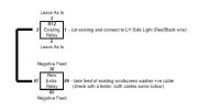
Retro fitted Headlamp Washer Relay Rewiring Circuit Diagram301 views
|
|
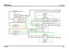
Thread upload23 viewsImage uploaded in new thread
|
|
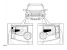
Headlamp Masking Diagram52 views
|
|

Parts diagram for 2007 D3 TDV6 HSE glass top aerial fin43 views
|
|
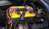
The auxiliary battery21 viewsThe auxiliary battery in the bay.
As the wiring diagram I made shows, there's a wire leading to the fuse box in the rear. (is going through the key-switch)
The second one is going to the fog lights. The smaller cables which should be connected to the head-lights, are connected to the battery.
The third one is going to the compressor (via a switch) (sits before the key-switch)
A fourth one is going to the CB and battery check display (sits before the key-switch)
|
|

Intelli Beam Wiring Diagram312 views
|
|

information and entertainment system (wiring diagram).pdf707 views
|
|

Information and Entertainment System - wiring diagrams14 views
|
|

128 viewsWiring Diagram for HEVAC-System
|
|

Key in Ignition Electrical Wiring Diagram1051 viewsThis shows the key in ignition wiring, (LGW, 1.5D), running from the key lock cylinder to the Central Junction Box, (CJB), thru 5 amp fuse F40P, located in the fuse box behind the lower glove box door.
You can remove the 5 amp fuse and the good news is that the ignition chime will not sound any longer; the bad news is that a bunch of other circuits that rely on knowing if the key is in or out no longer work.
Also note the Transponder Coil D219 reference.
|
|

Kenwood v1000 AV-Controller Install Diagrams132 views
|
|

Most ring26 views
|
|

Thread upload8 viewsImage uploaded in thread 199822
|
|

Discovery 4 MY2011 Electric Diagram Heated seats29 views
|
|

Thread upload14 viewsImage uploaded in thread 55010
|
|

Thread upload13 viewsschematic diagram of LED NAS light
|
|
Thread upload9 viewsImage uploaded in new thread
|
|
Thread upload6 viewsImage uploaded in thread 130779
|
|
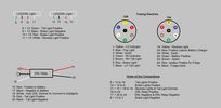
Thread upload7 viewsImage uploaded in thread 130779
|
|
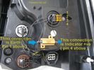
Thread upload15 viewsImage uploaded in thread 119434
|
|
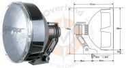
Lightforce 170 diagram details178 views
|
|
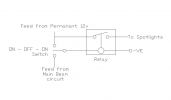
181 views
|
|
![Filename=Lighting_diagram[1].jpg
Filesize=26KB
Dimensions=952x556
Date added=15.Jan 2009 Lighting_diagram[1].jpg](albums/userpics/12442/thumb_Lighting_diagram%5B1%5D.jpg)
ON OFF ON Spotlight Wiring Diagram by UNG87 views
|
|
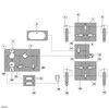
Block Diagram of Disco 3 / LR3 Air Suspension System.1552 views
|
|

Air System Schematic with parts identified.1374 viewsAir system block diagram with components numbered and identified.
|
|

Component Names related to Power Window Wiring Diagram283 views
|
|

LR3 Electrochromatic Interior Rear View Mirror wiring diagram.854 viewsIt seems that there are two fuses, F69P and F5P that provide power for the interior rear view mirror. Ten amp F5P is a feed off the reverse gear relay and inhibits auto dimming when reverse is selected. Five amp F69P provides power to the auto dimming circuits and the garage door opener function if optioned.
The pdf can be downloaded and printed out. For on screen viewing, right click on the pdf and select the Rotate Clockwise button.
|
|

Thread upload42 viewsImage uploaded in thread 47507
|
|

LR3 Air Conditioning High Line electrical wiring diagrams1466 viewsThis 7 page pdf shows the wiring for the Heater/AC both front and rear.
|
|

Console Gear Selector Wiring Diagram960 viewsThis is a 3 page wiring diagram centered around the console located gear selector.
|
|

LR3 Brake Wear Sensor Wiring1517 viewsThis 1 page wiring diagram pdf shows that both the front and rear brake pad wear sensors are part of a closed series circuit to ground.
In operation, when all is good, the series circuit is grounded and the amber brake wear warning indicator on the instrument panel is not illuminated.
When the pads on one wheel, either the left front, or right rear, become too worn, the respective sensor is "cut" which results in an open circuit condition. This causes the dash brake wear indicator to illuminate.
The circuit is like the old style Christmas light strings where one burned out bulb caused the whole string to go out.
A quick field fix to get the dash light to extinguish in lieu of replacing the sensor and pads etc is to disconnect the brake pad wear sensor and short across the two open conductors of the vehicle side connector plug. This of course means you now have a normal vehicle, one of the thousands that do not feature brake pad wear information systems.
|
|
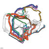
Thread upload0 viewsImage uploaded in thread 186579
|
|

Door Lock Wiring Diagrams1730 viewsNear the bottom of this 5 page pdf on page 224 are shown the pushbuttons and locking mechanisms for the rear hatch and tail gate.
The pdf will open vertically but you can download and print it out or just rotate the image clockwise by right clicking on your screen and selecting the "Rotate Clockwise" button.
|
|

Power Door Lock wiring diagrams530 viewsI thought I would include this 5 page power door lock wiring diagram pdf here as well.
When the pdf loads, if the views are vertical, it may be that you can right click on your mouse and a box will come up that will allow you to rotate the views clockwise so that the sheets are horizontal. Alternatively you can download the file and print each sheet yourself.
|
|

Power Door Lock Wiring694 viewsAbove is a 5 page, (pages 222 to 226), pdf wiring diagram for the power door locks for the LR3.
You can download and print as required. For on screen reading, use the right click rotate feature.
Additional pdf's regarding Locks can be found within the Gallery under the Power Windows and Door Lock Circuits heading.
|
|

Engine and Transmission Electronic Controls Wiring Diagram996 viewsThis 20 page pdf shows the wiring for the electronic controls for the engine, transmission and transfer case.
|
|

Horn Wiring Circuit LR3578 viewsThe is the wiring diagram for the dual horn circuit.
The Horn Relay, (R133), is not a big black thing hidden somewhere but instead what is called a FET, (and it is hidden)!
This is a Field Effect Transistor that is built into the circuit board that is mounted to the back of the fuse box that is located behind the lower glove box door on the passenger side of the 3. The related 15 amp fuse, 12P, is mounted in this fuse box and is often called F12P, where F is for fuse, and P is for Passenger compartment.
This is to help differentiate from another fuse and relay box, (the usual kind), that is located beside the starting battery in the Engine compartment. FxxE is often used in the naming of those fuses.
|
|

Heated Windscreen Wiring Diagram408 viewsThis single page pdf is the heated windscreen wiring diagram. You can rotate the view by right clicking on the pdf and of course it can be printed out as well.
Relay R208 in the pdf is relay R9 in the Engine Compartment fuse box. Note both 30 amps fuses, F15E and F18E, also located in the Engine Compartment fuse box. If one side of your windscreen does not heat, the problem may be one of the two fuses.
|
|

D3 Wiring Diagram102 views
|
|

Wiring Diagram167 viewsLR3 Wiring Diagram
|
|
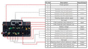
Thread upload1 viewsImage uploaded in new thread
|
|

NAS 7 plus 4 pin LR3 Trailer wiring, battery end. 549 viewsThis is the LR wiring diagram from the engine compartment battery location to the Electric Brake Controller connector, C2590, located under the dash near the brake pedal.
|
|

NAS 7 plus 4 pin LR3 Trailer wiring, trailer end. 498 viewsThis is the LR wiring diagram showing the conductors from the the Trailer Brake Controller connector, C2590, back to the rear combo NAS 7 plus 4 pin sockets.
|
|

ON OFF ON Spotlight Wiring Diagram by UNG119 views
|
|

18 views
|
|

15 views
|
|

Power Window Wiring Diagrams417 viewsThis pdf shows the power window wiring diagrams which are also shown as jpgs 1,2 and 3 below.
|
|

radio wiring diagrams84 views
|
|
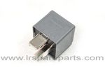
Air Compressor 70 amp replacement relay1393 viewsThere is a software update, 09 April 2010, LTB00270, for the compressor which reduces the shut down pressure to about 205 psig (14 bar). The update is usually done when changing to a new compressor and also includes replacing the R7 relay in the engine compartment fuse box, 07 DEC 2010 LTB00331.
The newer grey case coloured relay, part # YWB500220, shows to be rated at 70 amps, (the relay, not the compressor), however the previous black case coloured relay also indicates 70 amps.
Both the new and replaced relay show on their wiring diagrams to have a parallel voltage spike resistor, (probably 560 ohms), across the coil terminals, #1 and #2. This means one does not just replace the relay with any four prong 70 amp ISO sized relay that one happens upon.
One presumes the grey relay is either upgraded or just being installed for good measure. The relay is common on Ford Fiesta for the seat heater relay, Ford part number 5M5T 14B 192 EA; also Volvo, part number 30765034. The Tyco part number moulded on the grey body is V23136-J4-X62.
|
|

FBH Wiring Diagram30 views
|
|
Yet another diagram but same69 views
|
|
Yet another diagram but same 76 views
|
|
Wiring diagram heated seat 74 views
|
|

pdf wiring diagram147 views
|
|

Seat Heater Element wiring diagram34 views
|
|
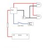
Spot or Driving Lamp Wiring Diagram312 viewsFor wiring non-LR lamps
|
|

Tekonsha P3 Brake Controller 90195 to Ford 3035-P wiring adapter plug311 viewsThis two page pdf is the general instruction for hooking up the Tekonsha part number 3035-P adapter cable between a Tekonsha P3 controller and the existing Land Rover/Ford plug, (called C2590 in the Land Rover wiring diagrams), that is hidden above the brake pedal.
The "Ford" plug, (C2590), is grey and is stuffed up above the brake pedal arm.
Mount the P3 controller appropriately and then connect one end of the custom cable to the P3 and the other to the "hidden" plug.
You will now have power for your trailer electric brakes in the round socket at the rear of your LR3; also no computer update from the Land Rover T4 unit is required. For once, it is plug and play.
If however, your trailer has LED tail lights, you may have trouble with the flashing of the trailer signal lights or non recognition by the 3 that a trailer is connected. As such, the little green trailer signal will not illuminate when a trailer is connected and the signal lights are used. This can affect the shifting of the transmission and much to your annoyance, the backup sensors will still be functioning rather than being auto disabled.
|
|

Airbag module removal tool diagram510 views
|
|
trailer wiring diagram212 views
|
|

upper tailgate5 views
|
|

Thread upload34 viewsImage uploaded in new thread
|
|

LR3 Vehicle Dynamic Suspension109 viewsLR3 Vehicle Dynamic Suspension wiring diagram
|
|
Thread upload5 viewsImage uploaded in new thread
|
|

Modified Wiring diagram for the added electrical bits29 viewsI made this wiring diagram during the cleanup I did lately.
I completely removed some 'old' electrical bits I had installed and used the occasion to document every left and new part.
|
|

LR3 Wiring Diagrams17 views
|
|

Thread upload34 viewsImage uploaded in new thread
|
|
Thread upload5 viewsImage uploaded in thread 132429
|
|
Thread upload10 viewsImage uploaded in thread 132429
|
|

Spot lamp / driving light DIY install wiring diagram98 views
|
|
|
|
|