| Search results - "con" |
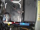
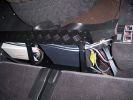
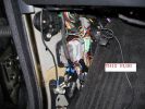
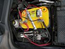
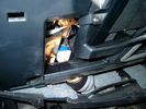
138 viewsThe weatherproof junction box fits neatly down the front of the battery, all contained inside the battery box.
|
|

RRSport Auto TDV6 0-100-0 times and G Forces156 viewsAir Temp 18, Dry conditions.
Best Acceleration G was .785 and decelleration G was 1.55
|
|
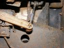
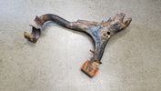
754 viewsNew control rod is carbonfibre/fibreglass hollow tube, with a rubber grommet fitted to one end (screwed and epoxy-ed) and steel rod bent into shape at the other (epoxy-ed).
|
|
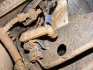
651 viewsNote blue rubber collar to hold lower part of control rod in arm.
|
|
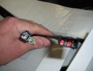
heated seat (base) wiring411 viewsThe Small connector takes the plug from the seat back pad, the larger connector (with red) is fitted into the multiplug casing uder the seat - the male side of this is already pre-wired.
|
|

Scorched Pad14 viewsThis is where the seat rod made contact with heating element.
|
|

gps version contents 146 views
|
|
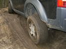
202 viewsDidn´t loose contact, but grip was zero.
|
|
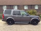
Disco 3 HSE in Bonatti Grey52 viewsPre the Disco 4 conversion and the 20" Landmark alloys
|
|

Disco abrasivo - Abrasive disc20 viewsDeclino ogni responsabilità per i danni che eventualmente farete direttamente o indirettamente seguendo questi consigli.
Per aprire la chiave ho usato un disco abrasivo da modellismo montato su un minitrapano. Deve giare velocemente.
Decline all responsibility for any damage that may directly or indirectly do by following these tips.
To open the key I used an abrasive disc mounted on a mini-drill. It must turn quickly.
|
|
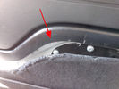
Rimozione pannello dalla sponda - Tailgate panel removing45 viewsPer togliere il pannello moquettato dalla sponda ho fatto leva con un cacciavite abbastanza grosso nel punto indicato, è stato veloce e non ho rovinato niente.
To remove the carpeted panel away from the tailgate I used a big enought screwdriver at the point indicated, it was fast and I have not ruined anything.
|
|

188 viewsOut at the local wind farm construction site.
|
|
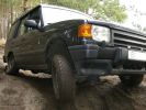
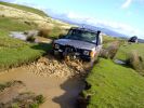
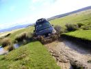
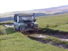
199 viewsSuspension working nicely. Thia model has no difflocks - not to mention electronics - to control wheel spin, so it needed speed to get through some points.
|
|

CALENDAR ENTRY 20091191 viewsBonatti grey TDV6 S, ambulance conversion, MTR's, winch, RAI, safety devices roof rack, rear ladder, bash plate, warn lighting, LED lighting throughout.
Owned by me, Rich Bell, Director of Extreme Medical Ltd, providers of medical support to Land Rover events.
|
|
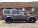
Disco 3 HSE in Bonatti Grey52 viewsPre the Disco 4 conversion and the 20" Landmark alloys
|
|

Tagliare lungo il perimetro della chiave - Cut along the key perimeter17 viewsI gusci sono saldati ad ultrasuoni. Con il disco tagliare lungo il perimetro della chiave in corrispondenza della giunta: lo spessore è di circa mm.3. Io non sono andato fino in fondo per evitare di danneggiare qualcosa, una volta inciso il solco per mm.2,7 ho fatto leva col cacciavite e ho strappato il materiale restante.
The body is ultrasonically welded. With the disc cut along the perimeter of the key in correspondence of the joint: the thickness is approximately 3mm. I have not gone all the way down
|
|
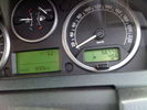
Fuel Consumption56 views
|
|

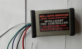
fbh controller7 views
|
|
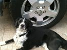
Len - constant companion122 views
|
|

Tagliare per eliminare parte del coperchio - Cut to remove part of the cover14 viewsE' meglio prima levare il circuito stampato e poi la lama della chiave, per evitare di danneggiarlo. Tagliare sopra il tasto superiore per rimuovere solo la parte con i tasti.
Is better to remove the printed board first then the key, to prevent damage. Cut over the top button to remove only the part with the buttons.
|
|
![Filename=033-[Sick]-[SuperEmoticons_com].gif
Filesize=1KB
Dimensions=64x32
Date added=01.Jan 2010 033-[Sick]-[SuperEmoticons_com].gif](albums/userpics/14643/thumb_033-%5BSick%5D-%5BSuperEmoticons_com%5D.gif)
51 views
|
|
![Filename=039-[Party]-[SuperEmoticons_com].gif
Filesize=3KB
Dimensions=40x60
Date added=01.Jan 2010 039-[Party]-[SuperEmoticons_com].gif](albums/userpics/14643/thumb_039-%5BParty%5D-%5BSuperEmoticons_com%5D.gif)
40 views
|
|
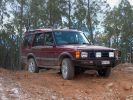
My Second Discovery, 2001 TD5 Manual38 views
|
|
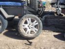
04 Damaged Tyre301 viewsYes, there\'s no doubt that this was a flat tyre. The ultra hot wheel nuts, look of the flat (note in a later photo that the back of the tyre appeared okay) and increased fuel consumption should have been a clue, but it was 45 deg C, and we had been doing about 105 km/hr on a dirt road for hours, so we just assumed it was a flat = WRONGO!
|
|

Estrarre il circuito stampato con la batteria - Exctact the printed board with the battery18 viewsRimossa la parte superiore del contenitore, estrarre il circuito stampato sollevandolo leggermente dalla parte della batteria.
Removed the top of the box, pull out the printed circuit board slightly lifting from the battery side.
|
|
![Filename=052-[Drinking]-[SuperEmoticons_com].gif
Filesize=14KB
Dimensions=67x40
Date added=01.Jan 2010 052-[Drinking]-[SuperEmoticons_com].gif](albums/userpics/14643/thumb_052-%5BDrinking%5D-%5BSuperEmoticons_com%5D.gif)
44 views
|
|
![Filename=058-[Drinking]-[SuperEmoticons_com].gif
Filesize=4KB
Dimensions=31x20
Date added=01.Jan 2010 058-[Drinking]-[SuperEmoticons_com].gif](albums/userpics/14643/thumb_058-%5BDrinking%5D-%5BSuperEmoticons_com%5D.gif)
50 views
|
|
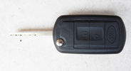
Chiave finita - Finished key18 viewsHo iserito il tutto nel nel nuovo contenitore pagato €4,00, ho incollato con la colla cianoacrilica, ne basta poca, e questo è il risultato.
I put all in the new container paid € 4.00, I glued with super glue, it only takes a little, and this is the result.
|
|

07 Back side of failed tyre340 viewsThis is the back of the blown tyre. It looks like any other worn tyre which has run a bit while flat. Note that we were running on wider 19" RRS wheels (have 4 19" MTRs + 1 old A/T on the original 5 wheels). Also have a rear-mount spare tyre holder which is really convenient with the wider rim and the fact that the tyre was still hot (it had some melted rubber on the other side!!)
|
|
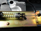
Cavo nel morsetto - Cable in clamp48 viewsHo inserito il terminale rotto nel morsetto: bisogna sforzarlo molto e ho praticato una cava attraverso il foro della vite con una punta in modo che il terminale non possa scivolare.
I entered the terminal broke into the clamp: you have to force it a lot, and I practiced a quarry through the screw hole with a bit so that the terminal can not slip.
|
|
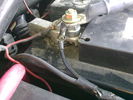
battery neg connection148 views
|
|
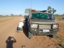
08 D3 stranded with a seized smoking wheel315 viewsAbout 1 hr after replacing the blown tyre, strange noises emanated from the stability control system and speed dropped off. Then I looked in the rear view mirror, and noted a cloud of dust along with a whiff of black smoke. This led to a very quick stop (no traffic on this route for over a week, so no worries about having to signal exiting the road). Took a look and WOW. The right rear wheel was glowing a dull red colour, and burning rubber smoke was wafting from the red glow over the fuel lines.
|
|

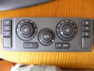
Climate control panel removal288 views
|
|

Ford Consul30 views
|
|
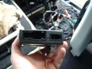
1 Nokia - Connections and loom appearing79 views
|
|
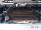
Removed Radiator Cover....wtf!!214 viewsThis gave me a few concerns
|
|

Compressore con base104 viewsIl materiale di partenza: compressore 12 volto senza base originale e con base fatta appositamente per il vano della 2° batteria del D3
|
|
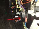
10 ICE Loom - Drivers kick ICE Loom / Dash Loom connector87 views
|
|
all lights switched on 79 viewsthis is the Bixenon with LR HID converted spotlights and the rigid SR40 lightbar switched on
|
|

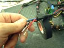
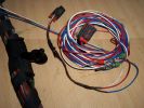
196 viewsCable loom with connector
|
|
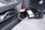
Centre console 12v & aux panel145 views
|
|
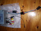
Full lead for DD conversion82 views
|
|
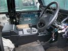
Temporary fit for Centre Console19 views
|
|
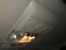
D4 353 viewsRear seat aircon gone missing
|
|

Iphone in D4435 viewsIphone connector
|
|

D4395 viewsInterior console
|
|

Floor console removal233 views
|
|

instrument panel console removal261 views
|
|

Floor console upper panel removal213 views
|
|
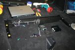
10260 viewsSet up all the controller components in the boot in the unused space available there. The V1000 is ready to be hooked up.
|
|
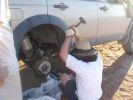
11 Lesson in removing a jammed brake assembly in the Outback378 viewsSpent the next 4 hours doing this to my D3. Gave the photos to Land Rover dealer and they did not think this constituted abuse of the vehicle. I thought that was charitable, but if we hadn\'t done this, the tow back to civilisation would have been even longer.
|
|
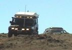
110 at Carinya Escapes ,Flinders ranges295 viewsDefender 110 Extreme,Long Range fuel tank,under floor water tanks, HF radio,GKN Overdrive,Swingaway Spare Carrier,70 litre Freezer,30 litre Fridge,Roof top Camper,Cruise Control,
|
|

Llamsrecovery mode installation53 viewsSpring lock inconspicuous
|
|

110 S Explorer Pack White Icon11 views
|
|
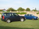
Quite a contrast!462 viewsMy outgoing Polo looked like a toy next to my new Disco.
|
|
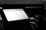
11207 viewsThe controller components are complete and fit neatly within the boot space.
|
|
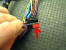
12 Dash Loom47 views
|
|
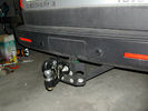
Gancio27 viewsGancio traino altezza variabile con attacco sfera e tipo ulpio
|
|
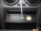
Centre console 12v & aux panel fitted281 views
|
|
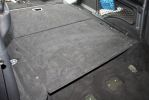
12220 viewsThe boot cover is back in place, hiding away all the controller components.
|
|
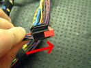
13 Dash Loom44 views
|
|
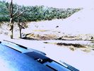
Recovery vehicle bogged for second time62 views
|
|
116 views
|
|
14 Dash Loom40 views
|
|
15 Dash Loom44 views
|
|

15 First sign of bits of parking brake failure336 viewsNote the complete lack of pad from the parking brake. Not only was there no composite brake material left, but the drum was somewhat twisted and connecting bits all smashed. Also a small drip of melted rubber from wheel bearing parts....
|
|
16 Dash Loom43 views
|
|

16-20200928_Vigor166_Physical_Connection23 views
|
|
![Filename=162-[Happy]-[SuperEmoticons_com].gif
Filesize=2KB
Dimensions=60x40
Date added=01.Jan 2010 162-[Happy]-[SuperEmoticons_com].gif](albums/userpics/14643/thumb_162-%5BHappy%5D-%5BSuperEmoticons_com%5D.gif)
44 views
|
|
17 Dash Loom44 views
|
|
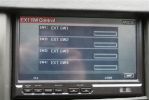
17298 viewsYou can add relay switches to the controller to turn on & off from the touch screen...pretty cool.
|
|
Thread upload9 viewsImage uploaded in new thread
|
|
Thread upload7 viewsImage uploaded in new thread
|
|

Under seat connector - manual122 views
|
|

Thread upload9 viewsImage uploaded in thread 155810
|
|
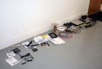
01313 viewsAll the new junk laid out on the floor.
Kenwood KOS-V1000 AV Controller
Kenwood KCA-iP500 iPod Control Interface
Kenwood KOS-L702 Monitor
Kenwood KCA-BT200 Bluetooth interface
Kenwood KNA-G510 Add-on navigation system
|
|
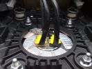
2 Airbag Connectors58 views
|
|
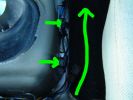
RH Side Ctr Csle46 views
|
|
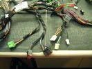
2 Dash Loom44 views
|
|
2 Dash SCREEN65 views
|
|
Second photo84 views
|
|

The ipod connected to AUX input3761 views
|
|
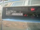
Socket for control lead and switch for radio-remote moved from solenoid pack to bumper1037 views
|
|

Bentley 98 views
|
|

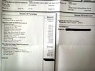
2009 Ford ESP Extended Warranty Contract144 views
|
|

Local WA newspaper article on D3 Theft168 viewsThe article is info by police public affairs. They wanted something to keep people locking doors and taking care during the holiday period. There are also TV public service announcements on air in WA featuring my wife confessing to leaving 1 door unlocked leading to the theft.
|
|

52 viewsFront suspension rebuilt in 2009 with reconditioned steering rack, new bushes etc..
|
|
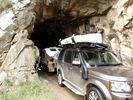
79 viewsConvict tunnel, hand dug
|
|

Drivers seat connector60 views
|
|

Drivers seat connector47 views
|
|

Drivers seat connector45 views
|
|
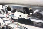
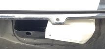
41 viewsDisconnecting the connector which gives power to the tailgate handle
|
|

75 viewsRemoved console surround trim
|
|
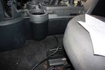
92 viewsStuffing cable under the floor console
|
|
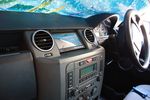
100 viewsScreen in place and console surround back on
|
|
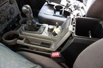
90 viewsLifted floor console upper panel to enable cubby box removal
|
|

usb/ipod connector 264 views
|
|

usb/ipod connector 55 views
|
|

most connector with 4 pin plug for usb/ipod module 57 views
|
|
Prototipo height controller miniaturizzato ANITAS 57 views
|
|

+7,5 cm + 5 cm offroad ANITAS height controller by mdm4x4.com metro49 views
|
|
+7,5 cm + 5 cm offroad ANITAS height controller by mdm4x4.com 256 views
|
|
+7,5 cm + 5 cm offroad ANITAS height controller by mdm4x4.com63 views
|
|
Controller +7,5 cm + 5 cm offroad ANITAS height controller by mdm4x4.com64 views
|
|
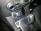
ANITAS D4 suspension module remote controller66 views
|
|

Fuel Consumption43 views
|
|

Fuel Consumption 237 views
|
|

Fuel Consumption graph33 views
|
|
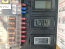
solar controller 48 views
|
|
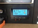
solar controller 60 views
|
|

waterproof connector for connecting camera on trailer 52 views
|
|
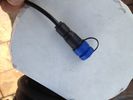
waterproof connector for connecting camera on trailer 48 views
|
|

waterproof connector for connecting camera on trailer 50 views
|
|
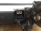
anderson connector at rear38 views
|
|
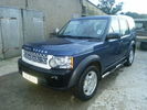
133 viewsD4 conversion before paint
|
|

Anderson Connector setup98 views
|
|
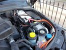
Anderson Connector setup91 views
|
|
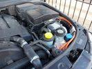
Anderson Connector setup85 views
|
|

Fuel Consumption 05/1324 views
|
|
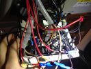
Roof Control panel25 viewsWell.. In reality it does not look as bad.. ;)
|
|
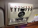
Roof Control Panel33 viewsThe "clean" side
|
|

Fuel Consumption26 views
|
|
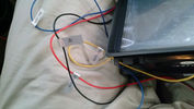
and where i supose to connect them on the car's stereo???19 views
|
|

connection the gps on the aux stereo's29 views
|
|

BOOT Rear Audio controls14 viewsBOOT rear audio wires
|
|

BOOT Rear Audio controls16 viewsBOOT audio wires
|
|

Audio control wiring loom LEFT16 viewsLeft Door wiring loom for audio controls
|
|

door loom plugs for window & audio12 viewsthe two plugs for the window & audio contros
|
|

Rear left door audio control loom12 viewsRear left door audio control loom
|
|
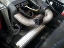
60 viewsBroken fbh connector
|
|
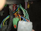
connector21 viewsLeft hand kick panel area
|
|

Terratrip 202 V4 possible discrete location140 viewsAttached to ashtray - allowing removal / unplugging when not in use by pulling out the ashtray.
Terratrip is an odometer for use in rallies / raids - very popular with the French when used in conjunction with a roadbook. A mechanical backup in case GPS signal is lost on modern odometers like the Globe 800 I propose to use.
We'll see if there are reflection issues from the screen.
|
|
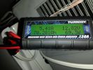
battery consumtion357 views24 hour power usage of an Engel 32L + NL 72L at 1c & -18c freezer in 80-92 degree heat in the shade. That's about 70amp hours.
|
|
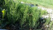
what plant22 viewswant to find out what this plant is and how best to control / remove it from garden
|
|
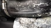
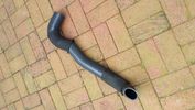
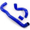
Thread upload132 viewsSplit after removing duck tape. I think the split got longer whilst waiting for new silicone hose's to arrive.
|
|
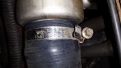
Thread upload126 viewsNew silicone hose with original sleeves refitted.
|
|
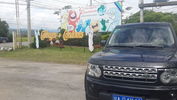
33 viewsNearside hose replaced with silicone type
|
|
cabbages and condoms20 views
|
|
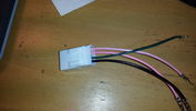
Adapter to connect to heat pad.11 views
|
|
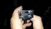
Connector on underseat harness for heated rear seats19 views
|
|
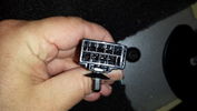
Connector from Main Loom to Heated Rear Seat Harness19 views
|
|
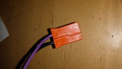
Side view of connector12 views
|
|
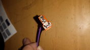
End of connector8 views
|
|
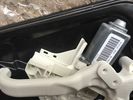
Rear window motor no grey connector11 views
|
|
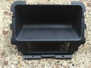
Rear Console trim which i replaced with one with heated rear seats.11 views
|
|
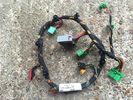
Front Console Wiring Loom AH32-14B079-BC Pic 39 views
|
|
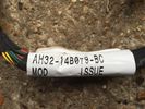
Front Console Wiring Loom AH32-14B079-BC Pic 27 views
|
|
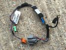
Front Console Wiring Loom AH32-14B079-BC6 views
|
|
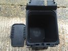
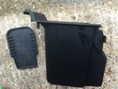
Centre Console Cubby with CD rack Pic29 views
|
|
Centre Console Cubby with CD rack9 views
|
|
Rear console Loom AH22-14K042-CB - Arm rest for aux audio fridge for fridge14 views
|
|
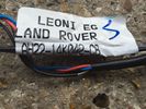
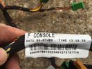
Wiring Loom F Console AH22-14B079-AC Pic36 views
|
|
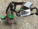
Wiring Loom F Console AH22-14B079-AC Pic211 views
|
|
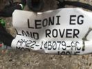
Wiring Loom F Console AH22-14B079-AC7 views
|
|
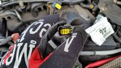
RH Glow plug connector16 views
|
|
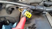
Test probe measure voltage18 viewsDo NOT insert the test probe into the connector as this can damage the terminal.
|
|
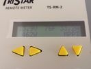
MPPT 45 Tristar 303 viewsThe morningstar Tristar MPPT 45 solar controller.
|
|
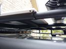
solar panel install356 viewsAt least at this point, I mounted it by using Clear Silicone RTV. This stuff is kind of like glue, but can be removed. If it doesn't hold up after curing and driving, I'll remove it and come up with another plan. I used heavy cable ties on the 4 grommets, in case it lets loose, it won't take out my wiring and the car behind me. 2 Panels are dandy like this, but I don't want to permanently block the roof space. Grape Solar to power my snomaster fridge
|
|
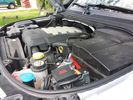
Winch Power upgrade318 viewsUsing 2 warn kits, and removing one of the wires to use on another project. The purpose was to replace the power and ground wire. I used Warn kits, which are 4/0 Welding cable. The original red #4 warped from getting a little too worn. The 2nd
Battery #1 Deka 9A94 AGM Intimidator, Battery #2 Deka 9A47 AGM Intimidator WARN 36080 28" Quick Connect Cable X 2, WARN 26405 Quick Connect Cable 7' X 2, WARN 15901 Black Cable X 1 -- winch control 72" X 1 https://www.facebook.com/DifferentialPartsUS
|
|
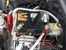
Wiring342 viewsThis is the final wiring configuration. It shows the dual battery wiring, 75A wiring run to the boot, the winch and in the lower right you can see a few turns of coax with a snap on ferrite near the base of a VHF Antenna.
|
|
Rear view camera connection 14 views
|
|

new silicone intercooler hose vs old one9 views
|
|
Connector 212 views
|
|
Connector6 views
|
|

Thread upload15 viewsImage uploaded in thread 148229
|
|
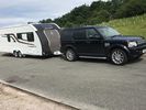
Swift 635 hitched to Disco 410 viewsSecond time out with new 2017 Swift Challenger 635 Hi-Style
|
|
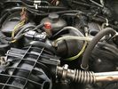
Boost pressure sensor conn.2 views
|
|
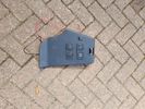
Rear Power Connectors7 views
|
|

Thread upload7 viewsImage uploaded in thread 184680
|
|

Thread upload5 viewsImage uploaded in thread 184680
|
|

Thread upload6 viewsImage uploaded in thread 184680
|
|

Thread upload4 viewsImage uploaded in thread 184680
|
|

Thread upload22 viewsImage uploaded in thread 184721
|
|

Thread upload22 viewsImage uploaded in thread 184721
|
|

Thread upload22 viewsImage uploaded in thread 184721
|
|

Thread upload1 viewsImage uploaded in thread 206617
|
|

Anti Lock and Traction Control description and operation.1986 viewsNote on page 6 of this 17 page pdf the significance of the Steering Angle sensor mounted on the steering wheel shaft. The paragraph regarding the plausibility check as related to the brake pedal being not depressed is why the clean operation of the second set of contacts on the brake switch matters so much.
|
|
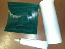
Contents of repair kit154 views
|
|

Steering Column detailing Steering Angle Sensor1496 viewsItem 2 in the picture on page 1 of the 9 page pdf shows the location of the steering wheel sensor. Page 5 of the pdf has a paragraph describing the operation of the sensor. When the steering wheel does not point the same direction as the real wheels, then the computers can put the 3 into safe mode and down goes the suspension. See also the 17 page pdf on the Anti Lock and Traction Control pdf.
|
|
HF radio on RH side Inverter on LH. Frame is fitted behind second row of seats. (I have removed 3rd row as they will never be used)310 views
|
|
![Filename=241-[Character]-[SuperEmoticons_com].gif
Filesize=0KB
Dimensions=29x31
Date added=01.Jan 2010 241-[Character]-[SuperEmoticons_com].gif](albums/userpics/14643/thumb_241-%5BCharacter%5D-%5BSuperEmoticons_com%5D.gif)
43 views
|
|
26 Dash Loom47 views
|
|
connectors99 views
|
|
connectors 2128 views
|
|
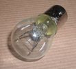
Land Rover Stop Tail Light dual filament bulb nominal 12 volt 21 / 5 watt filaments1427 viewsThis is the Land Rover part number 264590 dual filament bulb, (P21/5), that inserts into the upper two tail lamp receptacles. In the upper one, both filaments function, in the lower one, only the 5 watt tail light filament functions.
I regard it as not a good practice to routinely switch bulbs when the tail light filament, (5 watt), burns out on the lower bulb. The broken filament can jiggle over onto the brake light filament, (21 watt), and short the circuit to ground or something else not predicable.
There are also arguments to say that quality control is better on the Land Rover marketed bulbs than say far east sourced bulbs. Filament construction, and hence resistance can vary and mislead the current sensing circuits monitoring the signal light systems. Also when the bulbs are properly installed, all filaments should be standing vertically and not at any slope.
These are the sort of obscure circumstances that can lead to false trouble messages on the display, dropping to the stops, and subsequent concerns - all over a tail/signal light bulb.
For example, the filament life of both the tail light and the brake light filaments in the P21/5 bulb is significantly less than the USA common 1157 dual filament bulb, (1000/250 vs 5000/1200 hours); brightness in the P21/5 is a bit more, (3cp/35cp vs 3cp/32cp where cp is candle power), but current consumption is oddly less, (0.44a/1.86a vs 0.59a/2.10a where a is amps). It is the quest for efficiency vs maintenance trade off.
|
|
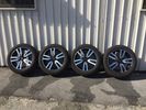
Ruote LR023736 con Continental 265/50R2025 views
|
|

Ruote LR023736 con Continental 265/50R2034 views
|
|

AIr con pipe81 views
|
|

Air con pipe65 viewsIts the brown pipe in the center of the photo. To remove this first you need to remove the "charge air cooler inlet hose" to allow access to the air con pipe securing fixings. But with the "charge air cooler inlet hose" disconnected it can\'t be removed from the veh because the air con pipe is in the way???
|
|
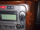
position of buttons for Parrot phone102 viewsthis can be put basically anywhere as it connect via bluetooth to the rest of the system. It is self powered (lithiam battery in it) so just stick it anywhere with no requirements for finding a live wire etc
|
|
![Filename=293x188_Content_MS_SnowF[1].jpg
Filesize=25KB
Dimensions=293x188
Date added=04.Oct 2012 293x188_Content_MS_SnowF[1].jpg](albums/userpics/10566/thumb_293x188_Content_MS_SnowF%5B1%5D.jpg)
42 views
|
|
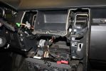
02279 viewsDash center console off and factory head unit out. LR clips suck.
|
|
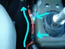
LH Side Ctr Csle52 views
|
|
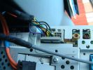
3 Dash Loom Rear of Display56 views
|
|
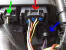
3 FBH Loom65 views
|
|
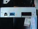
3 Navigation Bracket - nav connectors83 views
|
|
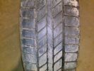
246 viewsContinental 4X4 Cross Contact
|
|

Engine Accessory Drive Description and Operation882 viewsThis 2 page pdf shows both belts for the 4.4L petrol V8; the primary serpentine belt, (the long one), and the shorter secondary that drives only the radiator cooling fan.
The various accessory pulleys the two belts are each associated with are numbered and an included table describes each.
When replacing belts and pulleys, count the number of grooves on both your old items and your new replacement parts. It has been known for an pulley with the wrong number of grooves to come with a replacement part or the replacement belt has the incorrect number of grooves; hence make certain the groove count on the new parts are the same as the removed items.
|
|
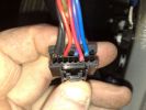
32 Dash Loom39 views
|
|
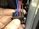
33 Dash Loom39 views
|
|
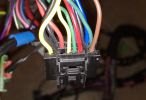
34 Dash Loom35 views
|
|
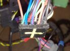
35 Dash Loom42 views
|
|

20 viewsPermette di svitare i bulloni delle ruote, ma anche di altro, con rapidità e senza grosso sforzo.
Si collega alla batteria dell'auto e non necessita del motore acceso.
|
|

Air suspension Control Module107 viewsDescription: Air suspension Control Module
Location: RH 'A' post
Part No.: YPC500830 Colour: NATURAL Cavities: 20WY
Harness: CABIN HARNESS
|
|
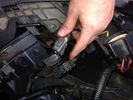
Thread upload47 viewsImage uploaded in thread 102519
|
|

3 Point Hitch on Series 90152 viewsUsually one sees the Series units with just a conventional field plow hooked to a drawbar hitch, tractor style. This jpg however is the full meal deal - a 3 point hitch, probably off a Fordson tractor, in the long tradition of Ford/Land Rover cooperation.
|
|
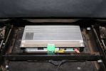
03285 viewsStock amp, underneath passenger front seat. In order to integrate the factory head unit with the V1000 we had to go through the stock amp. This is because of the MOST (fiber optic) connection between the two.
|
|
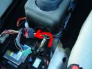
4 phone cadle loom routing51 views
|
|
4 Dash SCREEN56 views
|
|
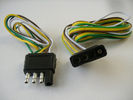
4 pin NAS flat connector from NAS small trailer382 viewsThe connector with the three exposed pins is the end that would commonly be located at the trailer hitch end, (front), of a small NAS lightweight trailer that has no electric brakes. This plug would connect into the flat 4 pin connector at the rear of the 3.
Note the order of the pin functions and wire colours: White is ground; the next pin is for tail/marker lights using the Brown wire; the Yellow conductor is for the left turn signal, and the far pin uses the Green conductor for the right turn signal.
There is no separate brake light conductor as NAS spec vehicles most often combine the brake and signal light functions to the same bulb filament rather separate filaments in different bulbs. The LR factory harness resolves that design difference.
Fortunately, the Land Rover NAS assembly pin order for the 4 pin flat plug maintains the above described conventions.
|
|

Air Conditioner Specifications 4.4L V81569 viewsThis 2 page pdf is just the specifications for the AC system. The refrigerant type is R134A.
Note that when topping the system up, it can be a good idea to include some of that ultra violet light dye that will glow to show leaks and loose fitting.
|
|

Rear Area Climate Control System1161 viewsThis 14 page pdf describes how the rear heating AC system is supposed to operate in conjunction with the front system.
The air transfer ducts are shown as coloured sketches as is the air flow within the rear blower setup.
|
|

Air Conditioning and Heater Control Components2425 viewsThis is a 21 page pdf that really explains how the air system is supposed to work. Discussed are the exterior ambient air sensor, where and how it operates; the interior temperature sensor as well as humidity sensor.
|
|

Connector C2149A21 views
|
|

Alternator and Regulator Wiring Diagrams, TDV6 and petrol V8 and V61989 viewsThis is a three page pdf that shows the alternator and regulator wiring for the petrol V6, petrol V8 and TDV6. The pdf can be either printed or by right clicking on the displayed pdf, rotated as required for viewing.
Of interest is that the regulator gets its instructions primarily from the Engine Control Module (ECM) and only secondarily from the vehicles electrical buss. The conductor from the battery thru the 5 amp fuse F20E is to provide initial power to excite the alternator at startup and then secondarily, to instruct it if the PWM signals were not available. Primary instructions to and from the ECM are thru the two other conductors via a digital like Pulse Width Modulated (PWM) signal.
If F20E, the 5 amp engine compartment fuse box fuse is blown, the red alternator light on the dash will be illuminated. This means that the alternator could be OK, but if the F20E fuse is blown, no electricity will be generated. Hence check the F20E fuse if you get a red ALT light or some indication of the alternator not working.
Regarding operation of the red ALT light on the dash, it is not the regulator within the alternator that tells the red light to illuminate, or not, but instead the ECM. This is the reason the red light does not function in the same manner as with older vehicles. With the 3, sometimes you have illumination and sometimes not depending upon what the ECM is thinking. What this means is that you can have an alternator that is failing but the red light does not illuminate as the ECM is compensating for reduced alternator output - maybe by draining the battery and or cutting back on vehicle electrical loads such as shutting off or cycling the radio amplifier or heated seats.
|
|

Fibre Optic MOST bus plus CAN, LIN, GVIF and SLIN buses1539 viewsThis 7 page pdf introduces the fibre optic MOST bus, (the orange coloured cables), the two high and medium speed CAN buses, the Gigabyte Video InterFace, Local IntercoNnect, and Security Local IntercoNnect buses.
|
|

Alarm System description and Operation1052 viewsThis 9 page pdf explains in detail how the anti-thief, (alarm), system is supposed to operate. The system uses the door ajar switches to provide alarm system signals; as such there are few separate contacts related to the alarm system only.
Page 6 of 9 is of particular interest as it describes the trigger log that is accessible with the dealer T4.
|
|
Heated Seat connections in front footwells 3189 views
|
|
Heated Seat connections in front footwells 2183 views
|
|
5 Dash SCREEN50 views
|
|
5 GPS Connectors GPS blue and Telephone burgandy72 views
|
|
5 ICE Loom - Location of pre fitted Voice / Speed pulse connector67 views
|
|

D4/LR4 501-12-floor console upper panel install instructions / german language72 viewsD4/LR4 501-12-floor console upper panel install instructions / german language
|
|
Thread upload175 viewsImage uploaded in new thread
|
|

Thread upload48 viewsImage uploaded in new thread
|
|

Thread upload4 viewsImage uploaded in thread 185650
|
|
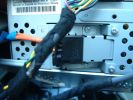
6 Dash SCREEN50 views
|
|
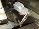
6 ICE Loom - Voice / Telephone & speed pule connector65 views
|
|
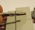
Connector sockets 8-12 & 21-2344 views
|
|

Connector: C2101104 viewsDescription: Rear control valve
Location: Below LH rear wheel arch
Part No.: YPC800230
Colour: BLACK
Cavities: 6WY
|
|

Concept trailer309 views
|
|
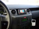
Navi Becker and iPod286 viewsThe Becker Highspeed II was installed in the bin with power connected. Works great, even TMC worked inside the garage right away!
|
|
Centre console.43 views
|
|
8 ICE Loom - routing at centre consoule66 views
|
|
08277 viewsRan the iPod connection up behind and through the center console. I'll be puting an iPod holder in the inside of the console lid.
|
|

Tools from dealer110 viewsThis is a cel pic of the tools from the dealer for install and removal of control arm bushings. minus one broken tool.
|
|
AUX Connection86 views
|
|
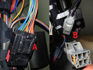
154 views
|
|
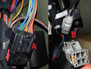
Thread upload46 viewsImage uploaded in new thread
|
|
Thread upload34 viewsImage uploaded in thread 131936
|
|
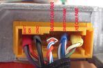
Retro Fit ACC ECU connections53 views
|
|

Thread upload35 viewsImage uploaded in thread 92518
|
|
359 views
|
|

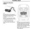
Audio Connectivity Module fitting instructions748 views
|
|
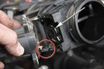
Removing the EGR Butterfly Valve Actuator1538 viewsRemove the 4 TORX screws to remove the actuator. The small black link (circled) connects the actuator drive arm with the butterfly valve spindle (arrowed). The spindle can now be very carefully levered out using a screwdriver inserted beneath the arrowed bit in the photo. A bit scary to do as it takes a fair bit of pressure before the spindle will free itself from the butterfly. Once it starts moving though, it gets easier to pull out.
|
|

Thread upload17 viewsImage uploaded in thread 187709
|
|

AC Control Components49 views
|
|

Add A Circuit Littelfuse Data sheet2278 viewsThe switch connects to what Littelfuse brand calls an Add-A-Circuit model FMH200BP which is an adapter that plugs in place of a Mini fuse and then has space for two Mini fuses, (original and a second one). In this install, only the original 5 amp fuse was used - adapter was so as to route power from fuse box thru fuse, then rocker switch, and then back to fuse box.
Before you install the Add A Circuit for this application, take an ohm meter and trace out the circuit path of the four slots that fuses could insert into. The path is more complicated than one might first think. As such, the orientation of the fuse holder in the socket matters for this application - that is for a circuit diverter, rather than accessory adder.
|
|

Sulfur_content_Africa229 views
|
|

Thread upload30 viewsImage uploaded in new thread
|
|

Air Con102 views
|
|
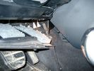
Air Conditioner Drain Hose on Drivers Side (LHD)2296 viewsThe corrugated rubber bit above and to the right of the gas pedal is the drain hose that goes down thru the carpet and floor sheet metal.
While it is bit hard to figure out from the jpg above, there is a rubber "strap" attached to the top of the corrugated hose that one uses to pull on to drag the hose up back around the black plastic heater "pan" drain. The same drain hose arrangement is on the other side as well.
One could I suppose run a plastic snap tie around the vertical pull strap if one was concerned about the hose slipping off again. See also the other jpg sketch which is from the Land Rover manual.
|
|
223 views
|
|

221 viewsSide view of airbag with home made tool connected.
|
|
Thread upload9 viewsImage uploaded in new thread
|
|
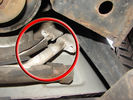
Air Conditioning Pipes (File 1)983 viewsIt\'s the smaller of the 2 pipes that is leaking. Both pipes are encased full length in the foam sleeve. You can see where the support bracket has \'crushed\' the sleeve. The bracket is what holed the small pipe. There is a bracket at each end and one in the middle. You need to remove the suspension reservoir to get to the centre bracket. Be aware that the bolts securing the brackets may be corroded and are likely to shear off on removal!
|
|
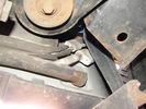
Air Conditioning Pipes (file 2)808 viewsShows location of front-to-rear air con pipes behind NS front wheel. You can just see the Vredestein tyre. The pipe connectors are tucked in behind the wheel arch inner cover. This has to be partially removed for access to bolts holding pipes together.
|
|
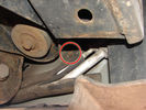
Air Conditioning Pipes188 viewsFront-to-rear aircon HP and LP pipes. The circled bit shows where the bolt securing the support bracket (removed)has sheared off
|
|
Thread upload19 viewsImage uploaded in thread 86429
|
|
Thread upload17 viewsImage uploaded in new thread
|
|

32 views
|
|

26 views
|
|

43 views
|
|
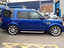
FOR SALE - ONE OFF Land Rover Disco 3 37 viewsOne of a kind Landrover Discovery TDV6 HSE LUX Model 5 door automatic 4x4 diesel evo blue. Upgrades: sidesteps, roof rails, privacy glass, front and rear heated seats/elec seats, landrover tv and headphones, 7 seater black leather, piano black dash/steering wheel, built in fridge, 6 disc changer, sat nav and bluetooth, harman kardon premium entertainment pack, by-xenon adaptive headlights , cruise control and front and rear park distance control, panoramic electric glass roof, 22inch alloy wheels, body kit
|
|

Alternator female plug looking down into top373 viewsThis shows the plug connected to the alternator wiring harness looking down into the top of the plug.
The cavity marked 1 is the AS or BATT SENSE and the wire colour most likely has Brown/Green on it.
The cavity marked 2 is the RC or ALT CON and the wire colour most likely has Red/White on it.
The cavity marked 3 is the L1 or ALT MON and the wire colour likely has Green/White on it.
I say "most likely" as the wire colours are not always the same on all vehicles.
Also the terminal 1 conductor destination is more likely C0570-175 rather than per the jpg.
The #3 pin is located closest to the big B+ terminal.
|
|
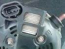
Alternator Plug and B+ terminal918 viewsPictured is the rear of the older Land Rover part # YLE500190 alternator showing the shiny cooling fin of the Regitar VRH2005-142 regulator under.
The first pin in the far left side of the connector is numbered #1 in the LR electrical wiring diagrams and is Battery Voltage Sensing (BVS); the middle pin, #2 receives a Pulse Width Modulated (PWM) signal from the Engine Control Module (ECM), and the right pin, #3 carries a PWM signal back to the ECM. Terminal Pin #2 on the LR wiring diagrams is called Alternator Control or ALT CON; Pin #3 per LR is called Alternator Monitoring or ALT MON.
Pin #1 is similar to what in older designs used to be called A or Batt, but is now called by Denso, S, AS, or Alternator Sensing for this design. Pin #1 also provides power to excite the alternator at startup until the PWM instructions over ride the battery voltage info. Land Rover calls the electronics under the pins a Smart Regulator, ironic, as it has to follow orders from the ECM rather than give the orders - new age thinking I guess. This is different from older design internal regulators that look at just the battery or the electrical buss voltage and then decides itself what to do.
It is almost like we are back to the external regulator designs of old, except that the ECM may decide that instead of telling the alternator to make more power, to load shed, and hence shut down the heated windscreen, seats, or whatever other electrical loads it decides are appropriate. My view is that the "smarts" are in the ECM and that the "regulator" should be regarded if not dumb, then as being a slave to the ECM.
|
|

Altox GSM GPS FBH controller66 views
|
|

Altox WBUS-4 Installation in Discovery 3126 viewsstep by step with pictures how to install the Altox WBUS-4 in the Discovery 3 in footwell
|
|
Thread upload6 viewsImage uploaded in thread 142542
|
|
376 views
|
|

Amplifier wiring98 viewsChanges for converting High Line to Premium.
|
|

28 views
|
|
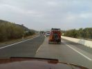
Looks like we got us a Convoy...161 views
|
|

41 viewsANITAS suspension module D4 MY2012 remote controller
|
|

anti lock control40 views
|
|
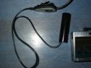
The cam with microphone/control buttons180 views
|
|
![Filename=Assisi 31-12-2008 03 - 01 gen 2009 - 03_M [1280x768].jpg
Filesize=134KB
Dimensions=1024x768
Date added=02.Jan 2009 Assisi 31-12-2008 03 - 01 gen 2009 - 03_M [1280x768].jpg](albums/userpics/12685/thumb_Assisi%2031-12-2008%2003%20-%2001%20gen%202009%20-%2003_M%20%5B1280x768%5D.jpg)
Il dosso....ma secondo voi quanto spazio c'era sotto?111 viewsLo vedrete nelle prossime foto....
|
|
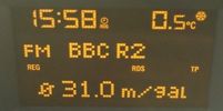
Astra 1.6 fuel consumption29 viewsFuel consumption of a 1.6 petrol Astra after a return trip from Aberdeen to Peterhead.
And yes I know i am sad listening to radio 2, but it was the only station I could understand up there.
|
|

205 viewsInstallation Instructions for ACM
|
|
Thread upload13 viewsImage uploaded in thread 64916
|
|

Thread upload15 viewsImage uploaded in thread 64916
|
|
Dicky helping,second time74 views
|
|
Aux Battery showing ground cable bolt "upside" down 1577 viewsIn order to obtain sufficient height clearance to get the plastic cover back on, I had to install the ground cable to the underside of the battery post connector.
Note the battery vent hose, (approx 5 ft required) is run down into where the windshield washer fluid container is located. There is not much electrical or metal in that area to be corroded by battery gas plus the open end of the vent hose tends to be protected from dirt and stays clean as well.
|
|

Aux Climate Control111 views
|
|
436 views
|
|
288 views
|
|
229 views
|
|
Aux Input Wiring Harness69 viewsUsed a modified PC CD interface cable to connect to stock female harness. Pins 3(R), 4(L), 5(G)
|
|

D4 Auxilliary or Second Battery installed in Aux Battery Box216 views
|
|
D4 Auxilliary or Second Battery installed in Aux Battery Box, Vents Circled192 views
|
|

auxiliary climate control51 views
|
|
Thread upload4 viewsImage uploaded in new thread
|
|
Thread upload11 viewsImage uploaded in thread 17945
|
|

Kenwood v1000 AV-Controller Diagram126 views
|
|
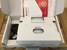
b-20200928_Vigor166_Box_Contents16 views
|
|
![Filename=ba2236-air-to-coil-conversion-kit-discovery-3-931977-p[ekm]170x113[ekm].jpg
Filesize=3KB
Dimensions=170x113
Date added=20.Sep 2017 ba2236-air-to-coil-conversion-kit-discovery-3-931977-p[ekm]170x113[ekm].jpg](albums/userpics/33392/thumb_ba2236-air-to-coil-conversion-kit-discovery-3-931977-p%5Bekm%5D170x113%5Bekm%5D.jpg)
Thread upload12 viewsImage uploaded in new thread
|
|
Thread upload12 viewsImage uploaded in new thread
|
|
30 views
|
|

6 views
|
|
Thread upload17 viewsImage uploaded in thread 166890
|
|

Thread upload9 viewsImage uploaded in thread 159579
|
|
Thread upload17 viewsImage uploaded in new thread
|
|

Thread upload17 viewsImage uploaded in new thread
|
|

Thread upload15 viewsImage uploaded in new thread
|
|
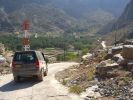
Bald Seet village164 viewsDescendign a steep concrete track over gravel into the villaeg of Ballad Seet. Curious in a dry, desert country to find verdent growth of palms, and agricultural produce on well watered terraces.
|
|

Thread upload13 viewsImage uploaded in thread 175878
|
|

Thread upload10 viewsImage uploaded in thread 135897
|
|
Thread upload9 viewsImage uploaded in new thread
|
|

61 viewsBAS defender 3.2TDCI 250bhp conversion.
|
|
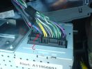
base radio aux connections665 views
|
|

Base Conversions122 views
|
|
9 views
|
|
9 views
|
|

76 views
|
|
38 views
|
|
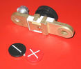
Battery Disconnect side post with + & - caps under view742 viewsThe upper and lower pieces of metal are clamped together but electrically seperate from each other. The connection between the two pieces is via the threaded part attached to the knob. When the knob is turned tight, current will flow between the two sections of metal.
|
|
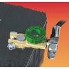
Battery Disconnect Wirthco 20308 Knob Top Post 890 viewsThis is a battery post style disconnect, usually for the negative terminal. There is a hole drilled in the round end off the battery so that flat terminal can be attached as well as the normal battery post terminal. I did not use this hookup arrangement, however I show it for information only.
|
|
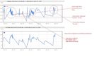
154 viewsRunning a 72L fridge on 100W solar with some driving. Conditions, overcast with some occasional sun. Overnight on Battery power. https://www.facebook.com/snomasterusa
|
|
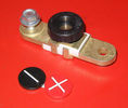
Battery Disconnect side post with + & - caps, top view617 viewsThis disconnect is designed for side post batteries. It can be used on either the + or - terminals. It can also be installed at the "other" end of the battery cable as well. In my install of the Aux battery, I installed this on the negative ground cable where the cable attaches to the body sheet metal. I have never used it but it seemed like a good idea at the time. The main battery hookup is pure stock.
For the hot side of the Aux battery, an Anderson PowerPole was used inline for the cable between the Aux and connecting to the spare bolt hole at the + post of the Main battery cable.
|
|
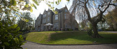
Woodlands Hotel6 viewsGreen Oval Garage would like to say thank you to the Woodlands Hotel in Leeds for allowing us the use of their beautiful grounds for all our future photos shoots.
Woodlands is one of the finest luxury hotels in Leeds. This boutique hotel is set in beautiful landscaped grounds on the outskirts of Leeds city centre, just 2 minutes drive from junction 27 of the M62 motorway, with 23 individually designed bedrooms and an award winning restaurant. Packed with character, this lovingly restored hotel is only three miles from the vibrant, cosmopolitan city of Leeds with superb nightlife and unrivalled shopping.
Woodlands also offers a stylish and contemporary functions venue for all kinds of social and business events. Our three stunning event spaces are suitable for everything from wedding ceremonies and receptions, to corporate meetings and events. The permanent marquee, attached to the hotel, can accommodate up to 150 for dining and 200 for evening parties and receptions, making it one of the most elegant settings for a wedding venue in the Leeds area.
For more information or to make a booking, please contact us on enquire@woodlandsleeds.com or 0113 2381 488
|
|

Thread upload14 viewsImage uploaded in thread 169863
|
|
Thread upload6 viewsImage uploaded in new thread
|
|
Thread upload6 viewsImage uploaded in new thread
|
|

Thread upload13 viewsImage uploaded in thread 123377
|
|
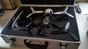
Parrot Bebop 2 Drone in case32 views£30 maplin case for Parrot Bebop 2 and Sky Controller 2
|
|
DG contemplating Andrews dustbin sized beer pots159 views
|
|
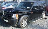
Bent Black Betty228 viewshard to believe that in this condition she\'s a write off, what got her was the cost of tricknology repairs, seatbelt pretensioners, airbags etc etc, & declining values, repair estimates €12500, value €13000. a no brainer really
Note TASTEFULL G4 sticker
|
|
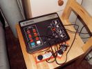
Latest ebay purchase a genuine 1977 Binatone Mk4 Games Console178 views
|
|
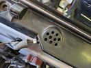
Buzzer located under black plastic cover.12 viewsThe white electrical connector clicks into the buzzer housing that is shown protruding from under the black plastic cover. There is a little tab on the white plastic that has to be squeezed to release the connector. In other words, do not pull on the two conductors.
|
|
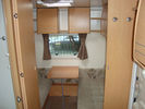
27 viewsthis converts to my sons bedroom and the door shuts across so we dont disturb him at night
|
|

10 views
|
|

bluetooth config194 views
|
|

Thread upload2 viewsImage uploaded in thread 190501
|
|

Thread upload14 viewsImage uploaded in new thread
|
|
Thread upload7 viewsImage uploaded in thread 163677
|
|

Thread upload17 viewsImage uploaded in new thread
|
|

Thread upload2 viewsImage uploaded in thread 192679
|
|
body control 161 views
|
|
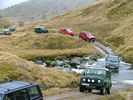
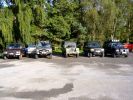
Another Highland 4WD Club Run. Boxing Day 2005, south of Inverness. We're in the second green 90.78 views
|
|
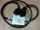
Box Closed with 7 Blade NAS connectors586 viewsBox closed up and ready for use. The box and cable connectors are reasonably weather tight and hence can be submerged for a bit while doing a creek crossing but as with the 3, do not use the creek bed as a parking stall. Similarly, the connector recessed into the bumper will probably remain somewhat dry as long as you keep moving but if you get stopped, well that is another story.
As such, I put a vial of desiccant in the metal box prior to closing it up to reduce corrosion due to moisture build up.
|
|

Black Deposits to interior of Brake Light Switch2860 viewsThere are two contacts, one on each side of the vertical plunger under the copper metal. The set of normally open contacts on the left side that carries the power for the brake light filaments, (15 amp fuse F15P), is apparently not heavy enough as the contacts deteriorate and generate the black residue.
The set of normally closed contacts on the other side appear to be sized OK. There is not as much current, (5 amp fuse F66P), flowing thru the contacts to the ABS module, however the contacts are likely adversely affected by the black residue produced by the other deteriorating set of contacts.
One presumes/hopes that the newer replacement switch now has contacts heavy enough to carry the brake light power. It would be ideal if the ABS set of contacts were sealed from the brake light contacts to prevent contamination of the normally closed set of contacts.
|
|

Brake Light Switch, Find, Remove, and Install Instructions 7851 viewsThis is a two page doc outlining where to find the brake light switch, how to remove it, and then install the new one.
Note, do not move the brake pedal when removing or installing the switch. Let the brake pedal hang where it wants to. The switch design is actually cunning, and as such is supposed to make the removal and install fool proof. Hence if you think too much about it, you can wreck the new switch.
If you want to inspect the interior of the switch, wait until you have removed the old switch. You can then just unsnap the blue from the white to get it apart. Inside, the switch is quite simple, (no circuit boards), but it will probably show black dust from failing contacts.
I think the reason the switch fails is that the Normally Open, (NO), contacts of the brake light contacts were made too light to carry the current load for make and break of the tail light filaments. I also think the black dust created then fouls the Normally Closed, (NC), second set of contacts for the ABS circuit. As such, the Normally Closed contacts become intermittent in operation and display as a fluctuating open and closed circuit condition to the ABS system when the ABS should be seeing a steady closed circuit. Hopefully the replacement switch contacts are more robust and may be as I recently replaced my switch again just as a matter of maintenance. While in a redesign, ideally the NC contacts should be sealed or at least separated from the NO contacts, when I inspected the removed switch, this time there was no black dust present.
Probably the removed switch will have a Land Rover oval logo moulded into it, the new one, FOMOCO.
|
|
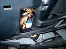
Brake Switch Visible thru Opening4973 viewsThe blue and white bit is the switch; the sort of gold appearing box,(it is really black), you will not see in your 3 as it is a Smooth Talker brand amplifier for my Blackberry phone antenna. This install is detailed in the SmoothTalker phone antenna section of my gallery.
One way to remove and install the switch is to lower the "horizontal" panel above the brake pedal as shown where the flashlight head is located. To actually remove the switch, you slide your hand thru the gap and rotate the switch clockwise 1/4 turn while watching thru the rectangular opening. Installation of the new switch is the reverse of above - 1/4 turn counterclockwise.
Before you remove the switch, note its orientation - horizontal with electrical wires to the left. That is the way it should look after replacement as well.
The second time I replaced the switch, I did it all thru the rectangular opening and did not remove the horizontal panel - that is experience helping out.
The knee kick you have to remove regardless. It is sort of hinged at the bottom so you just pull at the top and sort of rotate the knee panel and then pull upwards for two plastic "fingers" to clear the slots they reside in.
|
|
Smooth Talker Amplifier Box mounted below near steering column.179 viewsThe gold look box due to the lighting, (actually black), is the antenna amplifier located near the steering column. It can be put anyway but this seemed an OK location as I ran the antenna connector cable rearward from here to the back corner of the 3 and then up to the underside of the roof glass at the rear. The blue/white thing is the brake light switch that often must be replaced. See the Brake Light Switch file within this Gallery regarding the switch replacement.
|
|

Black Deposits on Brake Light Switch Plunger2757 viewsThis jpg I got off another forum and is typical of what one will see when one opens up the removed brake light switch. The black powder is residue from arcing of one of the pair of contacts within.
Hopefully the newer switches with the FOMOCO logo moulded into the plastic are improved from the Land Rover logo marked early units, however I doubt it.
The Ford part number is SW-6572 and/or 7E5Z-13480-A as used on the 2006 to 2009 Ford Fusion's and Mercury Milan's; the Land Rover part number is XKB500110. Cost of switch could be about twenty five dollars. A previous LR part number for the switch was XKB500030, so hopefully the newer LR part number, XKB500110, reflects some improvement in reliability.
It is possible that the new switches are better as I installed a replacement 72,000 km, (45,000 miles) later, at 195,000 km (121,000 miles). When I took the removed switch apart to inspect, it was clean inside. There was no black dust - the switch looked like new, hence they must be improved now.
|
|
259 views
|
|
281 views
|
|
305 views
|
|
272 views
|
|
261 views
|
|
283 views
|
|
312 views
|
|
458 views
|
|
360 views
|
|
382 views
|
|
407 views
|
|
466 views
|
|

371 views
|
|
362 views
|
|
400 views
|
|
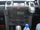
Brodit centre console mounts371 views
|
|
Thread upload16 viewsImage uploaded in new thread
|
|

BS emoticon69 views
|
|

113 views
|
|

343 views
|
|
Thread upload10 viewsImage uploaded in new thread
|
|
Burnt Bit97 viewsThis bit of wiring going to the connector was so close to bulkhead it got a bit burnt, Its for the clutch switch on a manual used for EPB, It will be replaced connector to pin with the wiring shown.
|
|
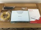
c-20200928_Vigor166_Contents74 views
|
|

D3 A Pillar Connector - C03361 views
|
|
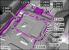
Camera Control Module D451 viewsHarness connection detail, camera module, located beneath L/H passenger side front seat UK D4 spec 2012.
|
|

Crap alert emoticon69 views
|
|
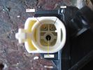
Camera connectors 284 views
|
|

D3 Side Step Repairs167 viewsWhilst I held the trim in place a second person inserted the rivets from behind the step edge. We started in the middle and worked out either way to ensure a snug fit of the aluminium trim.
|
|

CAN BUS MESSAGE15 viewsError I get when trying to read the Body Control Module Settings with my MSV2
|
|

changed car icon to black d3 147 views
|
|

84 viewsDescrizione struttura tenda (catalogo Conver mod. Orion4) da montare sul carrello per uso 4 persone
|
|

73 viewsMS excel sheet for monthly mileage report will give average fuel consumption.(most cells have formulas to help fill in from previous line)
on first sheet add details you want on monthly sheets. during use the data needed to be added is ending reading on clock, places visited (if you want).
how much fuel when you purchased it also fuel in tank at start and end of month
|
|
Other Dog157 views
|
|
Thread upload1 viewsImage uploaded in thread 196887
|
|
88 views
|
|

Unico neo della serata73 viewsIl menù stampato con scritto "Escursione in Jeep"!!!
A noi!!!
:|
|
|

Centre Console - back202 views
|
|

Thread upload6 viewsImage uploaded in thread 68494
|
|

Central Door Locking Operation Description1458 viewsThis 17 page pdf explains how the door locks are supposed to operate. Note that on page 9/17, the explanation of the operation of the hood ajar switch is wrong. It operates similar to the door and tailgate ajar switches; that is when a "door" is closed, the switch is closed to maintain a ground back to the CJB. Opening the hood, door, or tailgate removes the ground breaking the circuit and hence allows for an alarm condition.
|
|

Interior Trim268 views
|
|

Interior Trim367 views
|
|
Thread upload20 viewsImage uploaded in thread 161913
|
|
Thread upload1 viewsImage uploaded in new thread
|
|

Thread upload2 viewsImage uploaded in new thread
|
|

Thread upload5 viewsImage uploaded in new thread
|
|

Thread upload3 viewsImage uploaded in new thread
|
|

Thread upload8 viewsImage uploaded in new thread
|
|
8 views
|
|
7 views
|
|
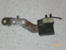
Condensatore (capacitor) 161 viewsZF catalog number 27.730 - LR number NNW502820
|
|
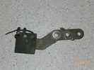
Condensatore245 views
|
|
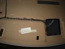
Hidden Mic Connector142 viewsMic connector on upper side of head lining just above & behind sun visor
|
|
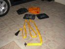
The kit as supplied180 viewsContains carry bag, 2 protector mats, exhaust jack and 7m reinfoced woven hose with bayonet connector to bag (inc non-return valve) and rubber cone for exhaust fitting
|
|
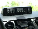
Mud UK switch binnacle453 viewsToo many switches for the roof mounted console, so this binnacle from Mud UK (desigend for the Defender) is an almost perfect match for the leather finished dash in the LR3. Switches, connectors etc bought from them too. From L - R switch functions are:
LH side mounted rack lamps
Driving lamps rack mounted
Spot lamps rack mounted
Bumper mounted driving lamps
RH side mounted rack lamps
Warn winch isolator
Rear mounted rack lamps (reversing)
Telescopic work lamp (fitted behind RH spare wheel)
|
|
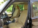
\'Escape\' canvas seat covers269 viewsFull set of these well made SA seat covers fitted to protect the Alpaca leather from constant exposure to Middle EAst sunlight and sand. They fit well, and to date have proved very durable. They include headrest and arm rest covers too.
|
|
| 2012 files on 6 page(s) |
 |
1 |  |
 |
 |
 |
 |
|