| Search results - "computer" |

Steering Column detailing Steering Angle Sensor1496 viewsItem 2 in the picture on page 1 of the 9 page pdf shows the location of the steering wheel sensor. Page 5 of the pdf has a paragraph describing the operation of the sensor. When the steering wheel does not point the same direction as the real wheels, then the computers can put the 3 into safe mode and down goes the suspension. See also the 17 page pdf on the Anti Lock and Traction Control pdf.
|
|

computer desktop13 views
|
|

Dog on computer26 views
|
|

The on/off switch for the middle outlet10 viewsThe left switch without the label is the one that now controls the middle 12V outlet on the second row. It used to be the power on/off of the car-computer.
|
|
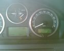
1003.5 km on ONE tankfull, 11L left according to onboard computer125 viewsmore than 1000 km (103.5) done on one tankfull, 11L left according to onboard computer
|
|

1730 viewsAnother viev of the computer and sub bass (sorry about the sun, it\'s rare here)
|
|

1521 viewsPicture showing two sub bass units and the computer mounted on a board in the newley aquired space.
|
|
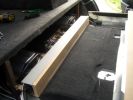
1492 viewsComputer and sub bass mounting board pusshed back into place
|
|
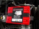
Aux Battery1054 viewsShows the aux 65Ah battery in place, top left of the picture is the 100amp circuit breaker feeding items sutch as , inverter, sub bass amplifiers, computer.
|
|
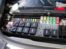
Picture of the engine compartment fuse panel5779 viewsEngine compartment fuse panel located near the battery. This is where F3E, (5 amp), F26E, (20 amp), Fuseable link 10E, (60 amp) and Relay 7E, the now upgraded 70 amp air compressor motor relay, part number YWB500220, (E is for Engine compartment fuse box), are all located. Fuse F35P, (5 amp), is inside the Passenger compartment behind the lower glove box door.
To keep the suspension from going down to the stops when driving, (or parked), it appears that it is only really necessary to remove F26E to depower the exhaust valve and generally keep all the valve block solenoid valves in a closed position trapping whatever air is within the air springs. F3E gets its power thru F26E, so when F26E is removed, the F3E circuit is automatically de-powered. F35P is more interesting in that battery power goes thru the ignition switch and F35P and then into the air suspension control unit. Apparently however, if F26E is removed, removing the F35P is not needed even when the engine is running.
With all fuses still in, if you have a problem, in practice, ideally, the compressor still works and will raise the 3 to an appropriate height. If so, one can then shut the engine off and allow the computers to go to sleep and then you remove the fuse(s). In actual practice, it seems that one need only pull the F26E fuse and can do so with the engine running. All the same, one might consider that the 3 is first a mobile computer, and secondly a 4x4. Computers prefer to go to sleep before the plug is pulled on them, however given that F26E circuit is always alive, then the computer never sleeps. With the fuse(s) pulled, and if you are still up, you can now be a 4x4 instead of a low rider. The whole purpose of the fuse pulling exercise is to depower the one and only system exhaust valve that is physically located within the compressor unit, (to keep it from opening), and secondarily to keep closed the four air spring solenoids within the block valves. This also shuts the air compressor down and stops the air compressor from making air even if the compressor is still good. That is why you initially need the fuse(s) in to allow the compressor to make air if it can.
|
|
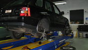
Rear Wheel Alignment.72 viewsBruce Davis Equipment for adjusting alignment alows the machine to hold the wheel camber caster etc after the wheel is removed to allow adjustments. The two spanners cannot be put on the adjusters with the wheel on the hub. His equipment has been modified to hold settings in its computer but allow accurate adjustment with the wheel off.
|
|
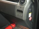
463 viewsFirst step in the journey, installed USB ports.
At the time I installed these, the goal was to use them in combination with the car-computer that resided in the back.
In the meanwhile, I dismantled the car-computer and nearly everything that was connected to it (touchscreen front, Wifi, DVB-T ...).
I kept the USB outlets in the front and turned them into charger for the appliances missus brings with her when we're on holiday. Mainly her iPod and smartphone ...
|
|
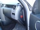
Air Suspension ECU Fuse 35P Shut Off Switch2635 viewsA more distant view of the shut off rocker switch in the ON position which is the normal position for when all is working as Land Rover intended.
Ideally, (but not totally necessary), the F35P circuit should be powered or de-energized after the various computers have gone to "sleep".
Similarly, removal of the F26E or F3E fuses is preferable after the computers have all gone to sleep but it appears that no real damage will be done if the fuses are removed while the system is energized. Pulling F26E is the main full time fuse that powers the air suspension computer. As such, once F26E is removed, pulling F3E is not really required.
Power for the compressor goes thru the 60 amp fusible link and relay, however control of the relay is via the air suspension computer so depowering the air suspension computer effectively depowers the air compressor and the internal exhaust valve relay/port.
|
|

LTB00159 - Technical Bulletin - Trip Computer Display Changes from Kilometers to Miles - Repair Procedure73 views
|
|

Thread upload9 viewsImage uploaded in thread 189719
|
|
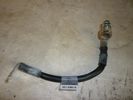
Negative Battery Cable208 viewsThis shows the corrosion from the negative terminal on the Negative to body ground. This is likely due to gas released through the negative post. It appears to be a common problem with the LR3. As a result of this corrosion left unchecked will damage the computer ecu and cables mounted near and below the battery.
|
|
Thread upload19 viewsImage uploaded in thread 174038
|
|

Transpo pdf explaining the operation of Ford PWM regulators624 viewsThe 4 page pdf produced by WAI-Transpo explains the operation of the Pulse Width Modulated regulators located within the alternators on our 3's. Of note, the pdf states that certain of the Ford PWM regulators do not meet Ford spec.
The pdf explains the function of all the terminals and the apparent advantages of the PWM style over previous designs. Note that Ford calls their "engine computer" a PCM, (Power Control Module), whereas Land Rover, an ECM, (Engine Control Module).
|
|

Thread upload5 viewsImage uploaded in new thread
|
|

Tekonsha P3 Brake Controller 90195 to Ford 3035-P wiring adapter plug311 viewsThis two page pdf is the general instruction for hooking up the Tekonsha part number 3035-P adapter cable between a Tekonsha P3 controller and the existing Land Rover/Ford plug, (called C2590 in the Land Rover wiring diagrams), that is hidden above the brake pedal.
The "Ford" plug, (C2590), is grey and is stuffed up above the brake pedal arm.
Mount the P3 controller appropriately and then connect one end of the custom cable to the P3 and the other to the "hidden" plug.
You will now have power for your trailer electric brakes in the round socket at the rear of your LR3; also no computer update from the Land Rover T4 unit is required. For once, it is plug and play.
If however, your trailer has LED tail lights, you may have trouble with the flashing of the trailer signal lights or non recognition by the 3 that a trailer is connected. As such, the little green trailer signal will not illuminate when a trailer is connected and the signal lights are used. This can affect the shifting of the transmission and much to your annoyance, the backup sensors will still be functioning rather than being auto disabled.
|
|

188 views
|
|
|
|
|
|
|