| Search results - "compressor" |

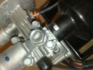
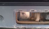
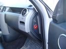
Put a link wire in these 2 holes (use a fairly thick wire ) - compressor will start ..you do not need the ignition on 941 views
|
|
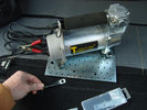
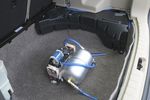
Compressore con base104 viewsIl materiale di partenza: compressore 12 volto senza base originale e con base fatta appositamente per il vano della 2° batteria del D3
|
|
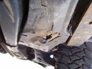
Compressor cover damage756 viewsAnother shot of the hole in the plastic cover
|
|
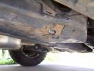
damage to compressor cover757 viewsHit a rock in Harvey and lost the compressor function. Went straight through the original plastic cover.
|
|
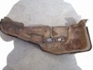
Compressor original cover657 viewsThe rock punctured straight through the plastic cover, snapped the soft compressor bracket and tore open one of the loom plugs.
|
|
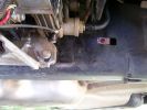
Repositioned compressor bracket737 viewsThe bracket was snapped in two, so I had it re-welded and slotted out the mounting holes so that it could be positioned 10mm higher (no longer protrudes under the chassis rail)
|
|
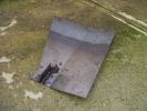
Steel compressor plate684 viewsIgnore my crappy welding attempts - I got a friend to finally weld the locator tab on the front!
|
|
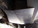
New compressor plate740 viewsFitted between the chassis rail and the new sill protector.
|
|

TB 149584 - Air Suspension Compressor and Relay Replacement41 views
|
|
Thread upload4 viewsImage uploaded in thread 194158
|
|
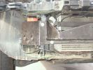
Compressor Valve Bracket910 views
|
|
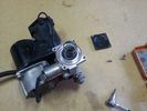
Compressore 455 views
|
|
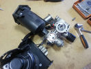
Compressore 348 views
|
|
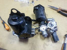
Compressore 240 views
|
|
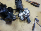
Compressore39 views
|
|
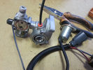
Compressore 1045 views
|
|
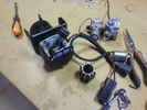
Compressore 940 views
|
|
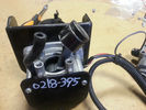
Compressore 845 views
|
|
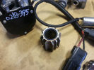
Compressore 739 viewsQui si vede bene la macchia di ossido dove sicuramente la guarnizione trafila.
|
|
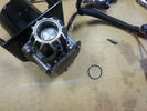
Compressore 638 views
|
|
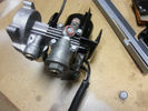
Compressore 536 views
|
|
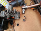
Compressor disassembled47 views
|
|
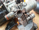
Compressor hole47 views
|
|
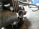
Compressor hole36 views
|
|
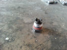
Compressor Nut39 views
|
|
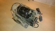
Hitachi compressor14 views
|
|
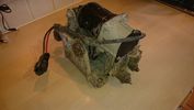
Hitachi compressor9 views
|
|
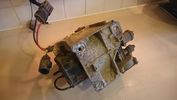
Hitachi compressor11 views
|
|
old air compressor5 viewsImage uploaded in thread 177818
|
|
new hitachi air compressor fitted1 viewsImage uploaded in thread 177818
|
|
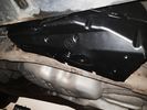
air compressor cover, lower1 viewsImage uploaded in thread 177818
|
|
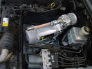
Compressore 12 volt 88 viewsEcco il compressore installato nel vano 2° batterie del Discovery3.
|
|
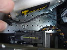
piastra compressore86 viewsParticolare dei bulloni di fissaggio della piastra al piano di appoggio del vano batteria
|
|
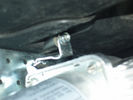
compressore 12 volt99 viewsparticolare della staffa a forma di Z che rende solidale la piastra alla parete del vano della 2° batetria
|
|
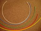
6mm Heat Shrink colours 362 viewsI decided to colour code the tubing so I used 6mm electrical heat shrink.
As there is no apparent colour coding re the 3, I tried to emulate the P38 coding; #1 LR red, #2 RR blue, #3 LF yellow, and #4 RF green. This was not doable as both left side air springs have green coloured tubing coming off the top of the front and rear air springs. I therefore arbitrarily chose the Left Rear to be red; Left Front green; Right Front yellow; Right Rear blue; and for the air compressor supply line, White coloured heat shrink. Since two new lines tie into each air spring line, I made the line between the air spring and the FASKIT, a single solid colour, and the line from the FASKIT to the valve block, White, plus the related appropriate solid colour.
|
|
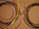
6mm PA12 grade nylon tubing with heat shrink applied 543 viewsShows some of the 6mm air line with heat shrink applied to one end of tubing. Shrink will be applied to the other end once field cut to length. These four tubes, each about 20 ft (6m) long, feed to the rear. Re the front air lines, (not shown), four additional lengths, each about 10 ft (3m) long, are required plus one more 3 metre length for compressor air. The 6mm tubing is a Nylon product specified as PA12. There is also a very similar Transport grade PA11 material, however it seems that PA12 is the more common Transport grade now in use. Also the applicable DIN standard seems to be both DIN 73378 and DIN 74324 for the nylon tubing. The working pressure of the 6mm tubing is about 27 Bar and bursting 82 Bar @ 20C. This is for the 1mm nominal wall thickness material, (4mm ID, 6mm OD).
|
|

A/C Compressor26 views
|
|
Thread upload413 viewsImage uploaded in thread 113599
|
|
9 views
|
|
Thread upload13 viewsImage uploaded in thread 176606
|
|

AMK_Compressor_Fitting_LTB0042042 views
|
|
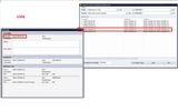
BBS SDD files for AMK64 viewsFile selection for BBS FFL for AMK compressors
|
|

Compressor type TSB108 viewsLand Rover TSB regarding Compressor type identification and fitment.
|
|
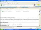
SDD screen shot for AMK compressors64 viewsScreen shot of SDD file selection for AMK compressors
|
|
Thread upload3 viewsImage uploaded in thread 201751
|
|
Thread upload2 viewsImage uploaded in thread 201751
|
|
Thread upload14 viewsImage uploaded in new thread
|
|
Thread upload47 viewsImage uploaded in thread 41187
|
|
Thread upload8 viewsImage uploaded in thread 166499
|
|
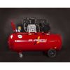
Thread upload14 viewsImage uploaded in thread 152582
|
|
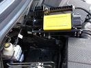
T-Max Adventurer 160lt/min Compressor too big for spare battery slot73 views
|
|
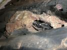
Compressor (somewhere)160 views
|
|
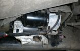
165 views
|
|
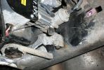
Compressor Bracket164 views
|
|
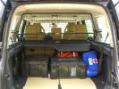
Load space368 viewsShows the SA Front Runner Wolfpack stacking plastic storage boxes that I keep laod straps etc in and the 2nd is tool kit, spare belts, jerry can funnel and tools, plus airline and tyre inflator/deflaotr for ARB on-board compressor, HD jump leads. ARB Winch pack (Orange)with strops, snatch blocks, shackles, gloves, and 2 ARB recovery dampers. Really great 4x4 1st Aid kit from Outdoors warehouse in SA. LRs own loadspace guard - not the best design if you want to store a long load. Mods to be carried out!
|
|

Cleaning Compressor Cover194 views
|
|
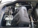
110 viewsTFC compressor in auxillary battery box
|
|
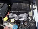
On Board compressoe location52 views
|
|

On Board compressor53 views150 litre per min compressor
|
|
181 views
|
|
Thomas compressor159 viewsCompressor mounted ontop of the rear wheel arch behind the plastics.
|
|

200 views
|
|

compressor removal.pdf667 views
|
|

302 views
|
|
123 views
|
|
25 views
|
|
Thread upload3 viewsImage uploaded in thread 67721
|
|
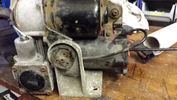
Thread upload10 viewsImage uploaded in thread 118155
|
|
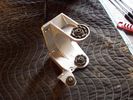
Air Compressor mounting bracket new907 viewsFound this jpg on a forum - thought it was good and is what one breaks when one jacks on the plastic air compressor cover.
|
|
Thread upload6 viewsImage uploaded in new thread
|
|
Thread upload12 viewsImage uploaded in new thread
|
|
Thread upload13 viewsImage uploaded in thread 166251
|
|
Thread upload2 viewsImage uploaded in new thread
|
|
Thread upload16 viewsImage uploaded in new thread
|
|
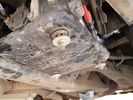
Thread upload13 viewsImage uploaded in new thread
|
|
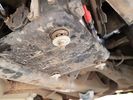
Thread upload12 viewsImage uploaded in thread 163989
|
|

Thread upload27 viewsImage uploaded in thread 173730
|
|

Thread upload3 viewsImage uploaded in thread 111638
|
|

Thread upload4 viewsImage uploaded in thread 199871
|
|

Thread upload4 viewsImage uploaded in thread 199871
|
|

Thread upload4 viewsImage uploaded in thread 199871
|
|

16 views
|
|

7 views
|
|

Thread upload4 viewsImage uploaded in thread 199871
|
|

Thread upload4 viewsImage uploaded in thread 199871
|
|
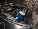
Thread upload6 viewsImage uploaded in thread 40682
|
|

Thread upload4 viewsImage uploaded in thread 199871
|
|

Thread upload4 viewsImage uploaded in thread 199871
|
|

52 views
|
|

Thread upload12 viewsImage uploaded in thread 100738
|
|

ARB air compressor switch, gauge, outlet.313 views
|
|

compressor temp23 views
|
|

compressor temp23 views
|
|
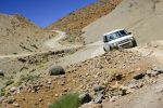
453 viewsMore photos coming soon. 7000 km with NO problem. Only took a 6th spare wheel, a tool box, air compressor, window shades. What a great Disco !
PS: note that my disco has manualy inflatable air sping in addition of the standar terrain response.
|
|
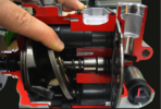
D3_aircon_compressor_maximum_swash_plate19 views
|
|
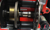
D3_aircon_compressor_minimum_swash_plate19 views
|
|

Thread upload6 viewsImage uploaded in new thread
|
|
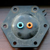
Crack in Compressor Dryer Cap 17 views
|
|
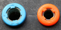
Crack in Compressor Dryer Cap 17 views
|
|
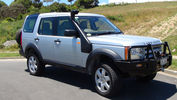
Disco 3 - 21 December 2012165 viewsJust back from having Front & Rear Bar, Compressor and Snorkel fitted.
|
|
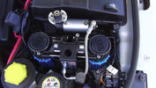
ARB CKMTA Twin Compressor180 viewsTwin Compressor with Manifold and Airtank. Tight fit but it fits. Also the ECU Chip is at the back and below up against the battery case.
I changed the hose quick release to a standard Air Hose Fitting eg like a workshop would use. My other truck has those also.
|
|
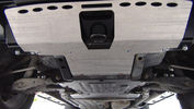
GOE Bash Plates119 viewsGreen Oval Experience Bash Plates. Front, Transmission and Compressor.
Might have to mod the front one a bit to let air into the trans cooler, it sits over the outside of the ARB bar which has vents for the cooler. If I cut slots in the Allow Plate to match those might do the trick.
I added a rear bolt to the Compressor Plate as it looked like it could get hooked on something and tear off. Two bolts onto the slider and two up onto the chassis now.
|
|
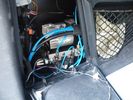
air compressor1 viewsair compressor
|
|
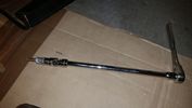
Thread upload18 viewsThis is how you reach that TOP BOLT holding your air compressor bracket on. 10" extension, swivel, and 10mm socket taped so it won't fall off while your feeding it through the air compressor maze.
|
|

Air fliter for compressor79 viewsfliter
|
|

Thread upload15 viewsImage uploaded in new thread
|
|
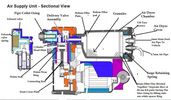
Thread upload35 viewsImage uploaded in thread 123822
|
|
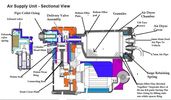
Thread upload6 viewsImage uploaded in thread 175852
|
|
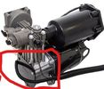
Thread upload2 viewsImage uploaded in thread 187145
|
|

Thread upload4 viewsImage uploaded in thread 199871
|
|

Thread upload21 viewsImage uploaded in thread 123657
|
|
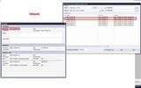
51 viewsFile selection for Hitachi compressor on the BBS FFL
|
|

SDD hitachi file selection55 viewsSDD screen shot showing files selected with an Hitachi compressor
|
|

How To - AMK Suspension Compressor Replacement by Disco_Mikey20 viewsA copy of Disco_Mikey's guide on how to replace AMK Compressor, complete with photos.
|
|
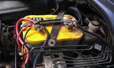
The auxiliary battery21 viewsThe auxiliary battery in the bay.
As the wiring diagram I made shows, there's a wire leading to the fuse box in the rear. (is going through the key-switch)
The second one is going to the fog lights. The smaller cables which should be connected to the head-lights, are connected to the battery.
The third one is going to the compressor (via a switch) (sits before the key-switch)
A fourth one is going to the CB and battery check display (sits before the key-switch)
|
|
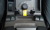
The on/off switch for the compressor12 viewsThe rocker switch for the compressor is the outer right one with the label of the .. euh, compressor :D
|
|
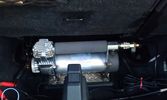
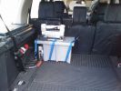
The compressor in the booth16 viewsThe rear of the second row seats are visible and the space behind was big enough to put the compressor.
The compressor is powered from the rocker switch in the front.
|
|
Outside connection to the compressor14 viewsFrom the compressor which is in the booth, the air hose runs to the back of the car.
I was able to install the connector in the space of the second trailer plug (which wasn't installed anyway).
|
|
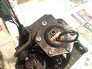
Old Compressor - temporary fix26 views
|
|
Compressor Relay29 views
|
|

broken air compressor bracket, side comparison with a new one2 viewsImage uploaded in thread 177818
|
|

57 views
|
|

Showing compressor, tank, pressure switch569 views
|
|

The Viair Compressor516 views
|
|
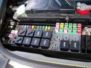
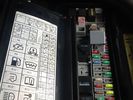
Picture of the engine compartment fuse panel5778 viewsEngine compartment fuse panel located near the battery. This is where F3E, (5 amp), F26E, (20 amp), Fuseable link 10E, (60 amp) and Relay 7E, the now upgraded 70 amp air compressor motor relay, part number YWB500220, (E is for Engine compartment fuse box), are all located. Fuse F35P, (5 amp), is inside the Passenger compartment behind the lower glove box door.
To keep the suspension from going down to the stops when driving, (or parked), it appears that it is only really necessary to remove F26E to depower the exhaust valve and generally keep all the valve block solenoid valves in a closed position trapping whatever air is within the air springs. F3E gets its power thru F26E, so when F26E is removed, the F3E circuit is automatically de-powered. F35P is more interesting in that battery power goes thru the ignition switch and F35P and then into the air suspension control unit. Apparently however, if F26E is removed, removing the F35P is not needed even when the engine is running.
With all fuses still in, if you have a problem, in practice, ideally, the compressor still works and will raise the 3 to an appropriate height. If so, one can then shut the engine off and allow the computers to go to sleep and then you remove the fuse(s). In actual practice, it seems that one need only pull the F26E fuse and can do so with the engine running. All the same, one might consider that the 3 is first a mobile computer, and secondly a 4x4. Computers prefer to go to sleep before the plug is pulled on them, however given that F26E circuit is always alive, then the computer never sleeps. With the fuse(s) pulled, and if you are still up, you can now be a 4x4 instead of a low rider. The whole purpose of the fuse pulling exercise is to depower the one and only system exhaust valve that is physically located within the compressor unit, (to keep it from opening), and secondarily to keep closed the four air spring solenoids within the block valves. This also shuts the air compressor down and stops the air compressor from making air even if the compressor is still good. That is why you initially need the fuse(s) in to allow the compressor to make air if it can.
|
|
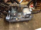
Workshop compressor14 views
|
|
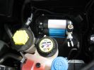
ARB under bonnet air compressor286 views
|
|

Compressor Guard18 views
|
|
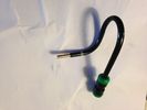
AMK compressor inlet pipe with brass fitting partially inserted16 views
|
|
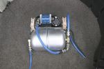
Thread upload3 viewsImage uploaded in thread 194158
|
|
Thread upload0 viewsImage uploaded in thread 201751
|
|
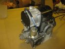
Compressor251 views
|
|
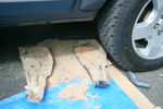
Cleaning compressor113 views
|
|
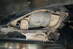
Compressor119 views
|
|
Thread upload1 viewsImage uploaded in thread 201751
|
|

Thread upload13 viewsImage uploaded in new thread
|
|

compressor dryer57 viewsleaking
|
|
![Filename=lr023964-dunlop-compressor-to-replace-pre-2010-hitachi-only-gb-made-1068977-p[ekm]169x170[ekm].jpg
Filesize=8KB
Dimensions=169x170
Date added=09.Nov 2018 lr023964-dunlop-compressor-to-replace-pre-2010-hitachi-only-gb-made-1068977-p[ekm]169x170[ekm].jpg](albums/userpics/33392/thumb_lr023964-dunlop-compressor-to-replace-pre-2010-hitachi-only-gb-made-1068977-p%5Bekm%5D169x170%5Bekm%5D.jpg)
Thread upload3 viewsImage uploaded in new thread
|
|
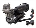
Thread upload11 viewsImage uploaded in new thread
|
|
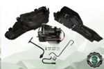
Thread upload13 viewsImage uploaded in new thread
|
|

Thread upload17 viewsImage uploaded in new thread
|
|
![Filename=lr072537-oem-amk-full-compressor-kit-to-replace-hitachi-or-amk-1244723-1-p[ekm]270x224[ekm].jpg
Filesize=15KB
Dimensions=270x224
Date added=26.Feb 2020 lr072537-oem-amk-full-compressor-kit-to-replace-hitachi-or-amk-1244723-1-p[ekm]270x224[ekm].jpg](albums/userpics/33392/thumb_lr072537-oem-amk-full-compressor-kit-to-replace-hitachi-or-amk-1244723-1-p%5Bekm%5D270x224%5Bekm%5D.jpg)
Thread upload11 viewsImage uploaded in new thread
|
|

Thread upload5 viewsImage uploaded in new thread
|
|
![Filename=lr078650-oem-amk-compressor-suspension-leveling-1244653-p[ekm]259x270[ekm].jpg
Filesize=15KB
Dimensions=259x270
Date added=26.Feb 2020 lr078650-oem-amk-compressor-suspension-leveling-1244653-p[ekm]259x270[ekm].jpg](albums/userpics/33392/thumb_lr078650-oem-amk-compressor-suspension-leveling-1244653-p%5Bekm%5D259x270%5Bekm%5D.jpg)
Thread upload11 viewsImage uploaded in new thread
|
|
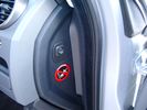
Air Suspension ECU Fuse 35P cut off switch.3820 viewsThis shows the SPST rocker switch mounted in the blank plate installed in lieu of a manual passenger side air bag shut down switch - now automatic via passenger seat pressure switch. Fuse 35P (5 amps) is located in the interior fuse box behind the lower glove box and protects the ignition power supply to the Air Suspension ECU. When the SPST switch is moved to the OFF position, the RAISE /LOWER switch on the centre console is not powered, and hence does not function. As such, some signals from the wheel height sensors and CPU are ignored. By itself however, removing F35P will probably not stop the 3 from self dropping, particularly after the engine is turned off.
Fuse F3E, (5 amps), located in the engine bay fuse box by the starting battery protects the circuit that provides feedback to the Air System ECU indicating that the Compressor Relay has successfully operated and that the Air Compressor is or should be operational, can also be removed, (but is probably not totally necessary), as it gets its power thru F26E. Hence Fuse F26E, (20 amp), also located in the engine compartment fuse box is the fuse that must be removed. This fuse protects the circuit that provides full time battery power to the Air System ECU. When in place, current thru the fuse powers the periodic re-levelling action, (usually lowering a bit with that brief air release noise), that often occurs when the vehicle is parked and the engine is off.
Removing F26E fuse will stop the auto levelling action and also inhibit any other down to the stops signals, (engine running or not). When F26E is removed, no power can flow thru to F3E, hence removing F3E is more for insurance than an absolute requirement. The same with F35P, removing F26E removes primary full time power from the Air Suspension ECU, and hence removing the F35P fuse should not really be required either as long as F26E has been removed.
|
|
Air Suspension ECU Fuse 35P Shut Off Switch2635 viewsA more distant view of the shut off rocker switch in the ON position which is the normal position for when all is working as Land Rover intended.
Ideally, (but not totally necessary), the F35P circuit should be powered or de-energized after the various computers have gone to "sleep".
Similarly, removal of the F26E or F3E fuses is preferable after the computers have all gone to sleep but it appears that no real damage will be done if the fuses are removed while the system is energized. Pulling F26E is the main full time fuse that powers the air suspension computer. As such, once F26E is removed, pulling F3E is not really required.
Power for the compressor goes thru the 60 amp fusible link and relay, however control of the relay is via the air suspension computer so depowering the air suspension computer effectively depowers the air compressor and the internal exhaust valve relay/port.
|
|
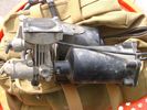
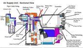
Compressor Air Drier 2044 viewsA view of the air drier - the black round thing to the right of the actual compressor cylinder head.
The general feeling is that the air dryer is responsible for most of the compressor problems now and that replacement of either the assembly or just the beads inside will probably revive one's compressor. In reality, the beads may have for the most part broken down and turned to dust plugging the internal filters. Hence replacement of the complete dryer unit has some merit.
The part number for the dryer assemble complete with the desiccant is VUB504700.
|
|
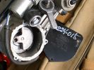
Compressor Con Rod Broken 1752 viewsThe model number of this compressor is RQG500060; the model number of my replacement compressor was LR015303, the unit that was apparently being installed on the D4 vehicles as of Spring 2010. As of Fall 2011, the new replacement part number is LR023964, the same as in the 4's.
Note the number hand written on the black plate. All the compressors seem to have some number hand written on them - hand built I presume, and every unit perhaps evolving a bit differently as LR struggles to build a compressor that will last. I guess Hitachi, (the manufacturer), should be given credit for that.
|
|
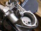
Compressor Con Rod Stud 1342 viewsVisible in the expanded view of this picture is the worn rounded threaded screw that tied the con rod bearing to the electric motor eccentric. I think the stud unscrewed itself and pulled out; then the piston jammed and the con rod broke.
|
|
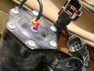
Compressor Electrical Plugs 1406 viewsThis shows the two electrical connectors; the two pronger is the power to the compressor, and the multi-pin connector carries control signals. Also the temporary red plug is where the 6 mm tubing from the centre valve block connects. This line carries both the compressor and exhaust air to and from the springs.
|
|
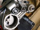
Compressor Exhaust and Inlet 1534 viewsThe two temporary black plugs cover off the 8mm and 10mm push fit lines to the air inlet and exhaust lines. Also visible is the worn threaded stud that I think was the initial failure mode.
|
|
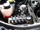
View of mounted panel from front left side877 viewsNote that all valve handles are shown in the OFF position, (the trouble position). In this case, the air that is in the air springs, (if any), is trapped in there - that is the valve blocks cannot vent whatever air is already in the air springs as the air lines between the springs and respective valve blocks are closed off by the FASKIT valves. In operation, there may be only trouble with one air spring, (perhaps a wheel height sensor), and as such, only one valve would need to be closed. If there was complete air compressor failure, then all valves would be closed and then as required, each spring could be manually filled from an outside clean dry oil free air source.
|
|
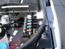
View from front left side looking towards rear aux battery compartment under cover 646 viewsAs there is no Fuel Burning Heater in the NAS V8 petrol vehicles, there is space available to install the FASKIT panel here. The piping is such that each air spring can be isolated from the air system and then filled one at a time manually via the Schrader valve. There are five Schrader valves and five shutoff valves. The fifth valve nearest the gauge controls air from the compressor, and can provide fill up air via a jumper fill line assuming the compressor is still operational.
|
|
Empty space in NAS LR3 for location of FASKIT panel599 viewsThe empty space is available as the North America Spec gasoline engine LR3's do not have the Fuel Burning Heater installed. The air lines from the four air springs and the air tank will appear to rise up from under the headlight assembly. The lines to the front block valve assembly located behind the front right fog light will sort of run within the bumper across the front of the radiator down into behind the righthand fog light. The rear lines somewhat follow the path of the existing air feed line from the front valve assembly to compressor. Rather than be located between the left front fender liner and left metal wing however, the four lines will feed thru the empty wing space inside and above the wheel well arch and exit down by the left front mud flap. From there, the lines run along the left frame member above the air tank and then parallel the frame over top the compressor to the top of the rear left air spring where the rear air block valve assembly is located.
|
|

Underhood Fuse and Relay Box drawing 3054 viewsShows the various fuse and relay locations. Fuse 3E, (5 amp), and Fuse 26E, (20 amp), as well as upgraded 70 amp Relay 7, part number YWB500220, locations are displayed. Relay 7 sends battery power to the compressor from the 60 amp fusible link called up as 10E. Fuse 26E is what provides full time always on battery power to the air suspension ECU and hence powers the auto level wakeup when the vehicle is shut down and say parked for the night. Removing F26E is the primary method to disable the air suspension system; Removing F35P is more if you want to experiment with it from inside.
I found it useful when I had a suspension problem, (actually a wheel alignment problem picked up by the steering wheel angle sensor), that only showed itself on the highway but allowed for no trouble light driving in the city. This was because in the city, the steering wheel was always in motion and rarely was the vehicle driven in a near straight line for very much distance.
|
|
Wiring, (tubing), loom exiting temporarily from the front right fog light.569 viewsThe front axle air valve block is located just behind and below the fog light. Access to the valve block is by removing the right front fender liner, (or the bumper). The FASKIT lines are attached to the left and right front air spring lines at this location; also compressor air is taken from this location as well. Cutting the lines at as few different locations makes it easier to find leaks at a later date. As above, five 6mm air lines run from the FASKIT panel to the front axle air valve assembly and run within the loom. Two pair of the lines are for control of the air springs, and the fifth line taps the air supply at the valve block assembly off the compressor. This will be the air source line rather than tapping in directly to the high pressure air tank.
|
|
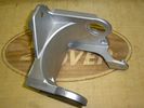
Replacement Bracket, LR part # RQU500064 for Air Compressor1025 viewsThis is a jpg of an aluminum replacement air compressor bracket, Land Rover part number RQU500064. The three rubber noise isolators are to be removed from the old bracket and inserted in the new bracket.
|
|
Thread upload1 viewsImage uploaded in new thread
|
|
Thread upload0 viewsImage uploaded in new thread
|
|

LTB00269 - Technical Bulletin - Air Suspension System - Compressor Delivery Valve and Drier Replacement Software Update2926 views
|
|

LTB00270 - Technical Bulletin - Suspension System Software Update When Replacing Compressor221 views
|
|

LTB00331 - Technical Bulletin - Air Suspension Compressor and Relay Replacement224 views
|
|

94 views
|
|
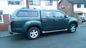
My Isuzu DMAX with Truckman Max Canopy30 viewsFinally got all the bits I paid for from the dealer - a Truckman Max Canopy and a spare wheel - unbelievably the default option on these is a can of foam and a compressor - thick end of £290 to get a full sized spare and the hoist to sling it underneath (much the same as a Disco, which means equally as stealable, might need to acquire a 17" spare protector of Uncle Ray)
|
|
Thread upload2 viewsImage uploaded in thread 175866
|
|
Thread upload4 viewsImage uploaded in thread 175866
|
|
Thread upload7 viewsImage uploaded in new thread
|
|
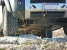
Rover Specialties Rock Sliders258 viewsRover Specialties Rock Sliders showing compressor protection
|
|
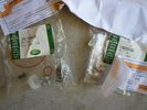
Both Compressor kits shown together426 viewsLR020590 KIT - COMPRESSOR 1
JPO500010 KIT - COMPRESSOR 1
|
|
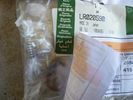
LR020590 KIT - COMPRESSOR 1481 viewsThere are 4 main parts you can get besides a whole compressor. This is the one with only a spring, o-ring and rubber valve.
YWB500220 electrical, fuse & relay, relay ENGINE COMPARTMENT, 70 amp 1
LR020590 KIT - COMPRESSOR 1
JPO500010 KIT - COMPRESSOR 1
VUB504700 - Dehydrator PARTS
|
|
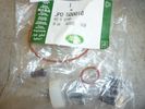
JPO500010 KIT - COMPRESSOR 1437 viewsThere are 4 main parts you can get besides a whole compressor. This is the one with more bits.
YWB500220 electrical, fuse & relay, relay ENGINE COMPARTMENT, 70 amp 1
LR020590 KIT - COMPRESSOR 1
JPO500010 KIT - COMPRESSOR 1
VUB504700 - Dehydrator PARTS
|
|
Air Compressor27 views
|
|

Air compressor45 views
|
|

Thread upload14 viewsImage uploaded in thread 126959
|
|
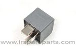
Air Compressor 70 amp replacement relay1393 viewsThere is a software update, 09 April 2010, LTB00270, for the compressor which reduces the shut down pressure to about 205 psig (14 bar). The update is usually done when changing to a new compressor and also includes replacing the R7 relay in the engine compartment fuse box, 07 DEC 2010 LTB00331.
The newer grey case coloured relay, part # YWB500220, shows to be rated at 70 amps, (the relay, not the compressor), however the previous black case coloured relay also indicates 70 amps.
Both the new and replaced relay show on their wiring diagrams to have a parallel voltage spike resistor, (probably 560 ohms), across the coil terminals, #1 and #2. This means one does not just replace the relay with any four prong 70 amp ISO sized relay that one happens upon.
One presumes the grey relay is either upgraded or just being installed for good measure. The relay is common on Ford Fiesta for the seat heater relay, Ford part number 5M5T 14B 192 EA; also Volvo, part number 30765034. The Tyco part number moulded on the grey body is V23136-J4-X62.
|
|
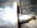
Reservoir Air In fitting installed 1660 viewsSchrader valve installed. Shop air can now be introduced into the tank to facilitate the raising of the 3 when there has just been a failure of the onboard air compressor rather than the electronics or valve block wiring etc.
Air could also be sourced from this point, however the purpose of the modification is air in, not air out as the air pressure normally runs above 200 psig, too high to be safe for routine use unless a pressure reducing regulator is added per the Mitchell Bros kit.
|
|
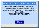
running compressor126 views
|
|

compressor repair tsb162 views
|
|
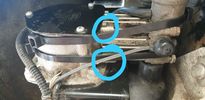
Thread upload2 viewsImage uploaded in new thread
|
|
![Filename=Technical Service Bulletin SB034 SB036 Vehicle Enhancement Program[1].pdf
Filesize=959KB
Dimensions=0x0
Date added=17.Jun 2010 Technical Service Bulletin SB034 SB036 Vehicle Enhancement Program[1].pdf](images/thumb_pdf.jpg)
Technical Service Bulletin SB034 SB036 Vehicle Enhancement Program2390 viewsOn page 6 and following are the Land Rover service bulletin instructions as to how to install delivery valve and exhaust valve repair kit JPO500010; also a list of previous compressor model numbers as related to the 3. The new delivery valve is easy to install, the exhaust, not so easy. Note that this in not the more recent TSB that reduced the operating pressure of the compressor via a software fix and also recommended replacement of the air compressor 70 amp relay. See the F35 album near the bottom for the relay material.
|
|
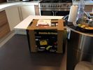
T-Max Adventurer 160lt/min Compressor parcel49 views
|
|
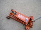
Trolley Jack Adapter823 viewsThis shows my 2.5 long ton, (2,540 kg, 5,600 pounds), trolley jack with the pin adapter that slots up into the round holes on the underside of the frame.
Use of the adapter when lifting by the left rear wheel ensures that I will not be jacking on the air compressor support; on the other three corners, it is much safer than merely jacking directly on the nearly flat narrow underside of the frame rail.
|
|
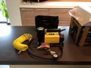
T-Max Adventurer 160lt/min Compressor, un-boxed 66 views
|
|
|
|
|