| Search results - "brake" |
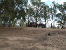
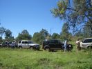
02 Last Photo before the little wheel problem saga222 viewsThis is my D3 with trailer on the banks of the Darling River, literally "back of Bourke" (the regional definition of the start of the Australian Outback). We were the first vehicle in a week to try and drive this route from Bourke to Wilcannia on the account of floods (first water in 7 years). Little did we know that 3 hours later there\'d be a bit of a wheel and tyre problem appearing...
|
|
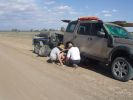
03 First bit of tyre/wheel trouble245 viewsIn the outback a tyre suddenly blew. "No worries" we thought, as we had 3 spares (+ two more if we abandoned the trailer), 150l of water, 3 days of food, and an EPIRB if things got really bad. At the time I didn\'t fully appreciate the fact that my index got a blister from the burning heat of one of the wheel nuts. It was 45 deg C at the time, so everything was hot.
|
|
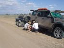
03 The first bit of tyre/wheel problem251 viewsSomewhere in the Australian outback on a 45 deg C day in Jan 08, a D3 had a bit of a flat tyre problem. "No worries, mate" st we had 3 spares (plus 2 more if we abandon the trailer), 150l of water, 4 days of food, and an EPIRB if things really go crook. The first clue that this was not a "normal" flat was when I handled a wheel nut and ended up with a blister from a burning hot nut (the ambient wasn\'t THAT hot).
|
|
04 Damaged Tyre301 viewsYes, there\'s no doubt that this was a flat tyre. The ultra hot wheel nuts, look of the flat (note in a later photo that the back of the tyre appeared okay) and increased fuel consumption should have been a clue, but it was 45 deg C, and we had been doing about 105 km/hr on a dirt road for hours, so we just assumed it was a flat = WRONGO!
|
|
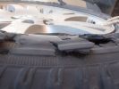
05 No doubt the tyre is flat275 viewsThis is the view of the flat tyre. Again, didn\'t think it anything more than a "normal" explosive blowout, as the tyre was about 90% worn, we were heavily loaded, it was 45 deg C, and driving 105 km/ho on a rough dirt road in the outback.
|
|
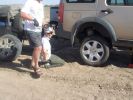
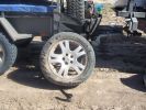
06 Spare tyre on and still suffering from hot wheel nuts296 viewsManaged to get ultra hot wheel nuts back on the spare (using the original 19" D3 wheel, vs the 19" RRS wider wheel which blew - shown in left of photo). Pity we didn\'t note that the disk brake was EXTREMELY hot at this time.
|
|

07 Back side of failed tyre340 viewsThis is the back of the blown tyre. It looks like any other worn tyre which has run a bit while flat. Note that we were running on wider 19" RRS wheels (have 4 19" MTRs + 1 old A/T on the original 5 wheels). Also have a rear-mount spare tyre holder which is really convenient with the wider rim and the fact that the tyre was still hot (it had some melted rubber on the other side!!)
|
|
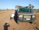
08 D3 stranded with a seized smoking wheel315 viewsAbout 1 hr after replacing the blown tyre, strange noises emanated from the stability control system and speed dropped off. Then I looked in the rear view mirror, and noted a cloud of dust along with a whiff of black smoke. This led to a very quick stop (no traffic on this route for over a week, so no worries about having to signal exiting the road). Took a look and WOW. The right rear wheel was glowing a dull red colour, and burning rubber smoke was wafting from the red glow over the fuel lines.
|
|

09 Starting to remove the seized brake assembly296 viewsBy this time we\'d poured about 8l of water on the dull-red glowing and burning wheel assembly (too close to 140l of 98 octane petrol). Sudden cooling cracked the disk brake which showed mangled park brake parts. How to remove a brake disk without the right star fitting? First remove the caliper then get a sledge hammer?!!
|
|

D3 Brembo Front and Rear Brake Upgrade pg1324 views
|
|

10 Cracked smoking parking brake drum338 viewsNote the crack in the face of the brake. This showed mangled parking brake springs and other bits. Also a bit of melted rubber was drooling out of the crack. Started to remove the brake caliper and enjoying the flies in 45 deg C heat. Ah, the wonderful Aussie climate in January.
|
|
D4 Brakes28 views
|
|
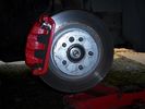
D4 Brakes28 views
|
|
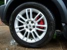
D4 Brakes.25 views
|
|
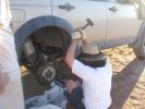
11 Lesson in removing a jammed brake assembly in the Outback379 viewsSpent the next 4 hours doing this to my D3. Gave the photos to Land Rover dealer and they did not think this constituted abuse of the vehicle. I thought that was charitable, but if we hadn\'t done this, the tow back to civilisation would have been even longer.
|
|

12 Half way through removing a jammed disk brake in the Outback297 viewsThis was just before breaking the sledge hammer. Note we luckily carried a spare hammer. Ended up using (or breaking) every tool we had on this little repair job. Bed sheets are a good way of gathering the bits to show for the inevitable warranty claim.
|
|
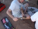
13 How to care for tools303 viewsWhat happened to the sledge hammer after 2 hours of beating my seized and cracked disk/park brake assembly to bits. Now down to 1 hammer remaining. At least by this time it was getting cooler (down to 40 deg C)
|
|
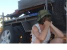
14 "Are we having fun yet?"349 viewsSWMBO is pondering why attempting to drive 3,900 kms across the outback on dirt roads is more fun than, say, spending New Years in Paris......
|
|

15 First sign of bits of parking brake failure336 viewsNote the complete lack of pad from the parking brake. Not only was there no composite brake material left, but the drum was somewhat twisted and connecting bits all smashed. Also a small drip of melted rubber from wheel bearing parts....
|
|
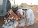
16 All the remains of a D3\'s parking brake373 viewsAfter 4 hours of hammering, finally removed the disk/park brake drum, and nearly all the parking brake bits fell to the ground. Cut rhe remaining brake cable loose as it was wrapped around the hub and a bit melted. Also having 2 jacks + 2 jack stands will support 4 hrs of hammering on the side of my D3.
|
|
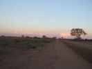
18 Brake "repairs" finished at sunset296 viewsWe just finished the repair at sunset and were driving slowly with 3 brakes. Oddly the D3 didn\'t behave any differently at 50 km/hr than it did normally. We had 4 instances of hitting the (3) skids for kangaroos before arriving in Wilcannia 3 hrs later. The brake light warning was making very distinctive noises and flashing randomly, though.
|
|

D3 Brembo Front and Rear Brake Upgrade pg2324 views
|
|
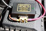
132 viewsTraxide SC80 brain modified. Cut the studs down to the nuts and removed the rubber cover. Had to do this as otherwise it wouldn't fit comfortably and would squash the brake vacuum pipe
|
|

122 viewsTraxide brain mounted. It's mounted slightly tilted towards the front of the engine bay so as to give as much space as possible to the brake vacuum pipe behind it.
|
|
3mm brake pads...not27 views
|
|
brake master cylinder + servo LHD11 views
|
|

Brake shoe arm 20 viewsCable retaining spring location
|
|

Brake shoe arm23 viewsCable retaining spring location 2
|
|
Thread upload10 viewsImage uploaded in thread 163538
|
|
Thread upload14 viewsImage uploaded in thread 174389
|
|

Thread upload4 viewsImage uploaded in thread 198055
|
|

Anti Lock and Traction Control description and operation.1987 viewsNote on page 6 of this 17 page pdf the significance of the Steering Angle sensor mounted on the steering wheel shaft. The paragraph regarding the plausibility check as related to the brake pedal being not depressed is why the clean operation of the second set of contacts on the brake switch matters so much.
|
|
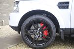
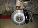
Brembo front brakes on D415 views
|
|
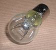
Land Rover Stop Tail Light dual filament bulb nominal 12 volt 21 / 5 watt filaments1427 viewsThis is the Land Rover part number 264590 dual filament bulb, (P21/5), that inserts into the upper two tail lamp receptacles. In the upper one, both filaments function, in the lower one, only the 5 watt tail light filament functions.
I regard it as not a good practice to routinely switch bulbs when the tail light filament, (5 watt), burns out on the lower bulb. The broken filament can jiggle over onto the brake light filament, (21 watt), and short the circuit to ground or something else not predicable.
There are also arguments to say that quality control is better on the Land Rover marketed bulbs than say far east sourced bulbs. Filament construction, and hence resistance can vary and mislead the current sensing circuits monitoring the signal light systems. Also when the bulbs are properly installed, all filaments should be standing vertically and not at any slope.
These are the sort of obscure circumstances that can lead to false trouble messages on the display, dropping to the stops, and subsequent concerns - all over a tail/signal light bulb.
For example, the filament life of both the tail light and the brake light filaments in the P21/5 bulb is significantly less than the USA common 1157 dual filament bulb, (1000/250 vs 5000/1200 hours); brightness in the P21/5 is a bit more, (3cp/35cp vs 3cp/32cp where cp is candle power), but current consumption is oddly less, (0.44a/1.86a vs 0.59a/2.10a where a is amps). It is the quest for efficiency vs maintenance trade off.
|
|

D3 Brembo Front and Rear Brake Upgrade pg3282 views
|
|
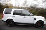
Brembo brakes on D49 views
|
|
Thread upload3 viewsImage uploaded in new thread
|
|
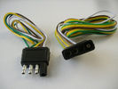
4 pin NAS flat connector from NAS small trailer382 viewsThe connector with the three exposed pins is the end that would commonly be located at the trailer hitch end, (front), of a small NAS lightweight trailer that has no electric brakes. This plug would connect into the flat 4 pin connector at the rear of the 3.
Note the order of the pin functions and wire colours: White is ground; the next pin is for tail/marker lights using the Brown wire; the Yellow conductor is for the left turn signal, and the far pin uses the Green conductor for the right turn signal.
There is no separate brake light conductor as NAS spec vehicles most often combine the brake and signal light functions to the same bulb filament rather separate filaments in different bulbs. The LR factory harness resolves that design difference.
Fortunately, the Land Rover NAS assembly pin order for the 4 pin flat plug maintains the above described conventions.
|
|

D3 Brembo Front and Rear Brake Upgrade pg4329 views
|
|
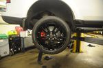
Brembo rear brakes on D47 views
|
|

Thread upload8 viewsImage uploaded in thread 195195
|
|

D3 Brembo Front and Rear Brake Upgrade pg5260 views
|
|

6 Brake System19 views6 Brake System
|
|

Thread upload17 viewsImage uploaded in new thread
|
|

Thread upload14 viewsImage uploaded in new thread
|
|

Land Rover Aerial Fin images for both Glass and Metal Roof Disco3 / LR3864 viewsAs well as the two different fins, this pdf also shows the plastic blanking plate for glass roof vehicles where no fin is installed.
The glass roof fin is secured by two security screws from the top into a plastic frangible glue on gasket. The hope is that when struck, the fin will shear off and not crack the glass roof. Re the metal roof design, the fin is secured from underneath via two nuts.
The pdf also shows the various electrical bits related to the antennas. In the UK, the fin would house not only a cell phone antenna but the TV and satellite radio antenna electronics as well; in the States, the Sirius sat radio antenna and a G type cell phone antenna if the phone kit was installed would reside within the fin. The SAT NAV GPS antenna is located within the High Mount Brake Light plastic mounted to the upper rear hatch.
|
|
Thread upload14 viewsImage uploaded in thread 157748
|
|
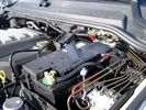
BCI Group 40R Deka 640RMF battery showing vent hose run forward to windshield washer reservoir area 1430 viewsRecessed post "Euro profile" battery to "match" OEM and stock Land Rover bracket; note that the Traxide SC80-LR module is mounted at an angle to allow for the main cable to sit under the cover so cover still closes.
The battery is a nominal 7", (180mm), high, but sits on a 1" battery spacer set under to raise the bottom front end of the battery such that the approx 11", (290 mm), length of the BCI 40R battery rises above the angled plastic nibs at the forward end bottom of the case front; hence sufficient space, (1/4", 5mm) remains at the brake reservoir end.
Also the 40R battery does not have hold down "flanges" on each end; on the sides yes, but not the ends so no additional length is required.
When I had to replace the 40R, this time I installed the shorter, (9.625"), taller, (7.5") Interstate BCI 47 / DIN H5 battery which eliminated the spacer on the bottom and better fit the stock LR tie down bolt lengths. Deka also has a BCI 47 / DIN H5 that would work fine as well.
|
|

OLD VERSION Please check folder for newer. Bodsy's Brake Bible V1.2a6906 views
|
|

OLD VERSION Please check folder for newer. Bodsy's Brake Bible V1.32420 views
|
|

OLD version Bodsy's Brake Bible V1.3 +text change2207 viewsMinor Text Change updated P7 and P9.
|
|

OLD Version - 1.42345 viewsSee Version 1.5
|
|

OLD VERSION 1.5 - See v1.62887 viewsOLD VERSION - See v1.6
|
|

5 views
|
|

Bodsy's Brake Bible Version 1.6a - LATEST VERSION32091 viewsMinor updates from Version 1.6
|
|

39 views
|
|

Thread upload8 viewsImage uploaded in thread 206752
|
|

Bodsy Brake Bible en Francais 1.6a4073 views
|
|

Thread upload3 viewsImage uploaded in thread 206752
|
|

Thread upload7 viewsImage uploaded in thread 206752
|
|

OLD VERSION - Bodsy's Brake Bible v 1.611172 viewsUSE Version 1.6a
Clarified EPB shoe instructions & corrected references to other sections. Added paypal donations information (requested by users of the guide.) Internationalised wheel location references by removing UK based reference to OS/NS, replaced with physical Front Left or Front Right descriptions.
|
|

102 views
|
|
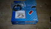
Brake Kit Front14 views
|
|
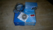
Brake Kit Rear14 views
|
|
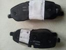
38 views
|
|

44 views
|
|

35 views
|
|

34 views
|
|

40 views
|
|

28 views
|
|

30 views
|
|
Thread upload31 viewsImage uploaded in thread 130779
|
|

Thread upload9 viewsImage uploaded in thread 159029
|
|

Thread upload15 viewsImage uploaded in new thread
|
|

44 views
|
|

Uneven wear61 views
|
|
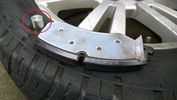
Front Brake Pad31 views
|
|

Brakes Details45 views
|
|
Thread upload8 viewsImage uploaded in thread 178484
|
|
Thread upload0 viewsImage uploaded in new thread
|
|

Thread upload4 viewsImage uploaded in thread 183794
|
|

Thread upload1 viewsImage uploaded in thread 194599
|
|

Thread upload5 viewsImage uploaded in new thread
|
|
48 views
|
|
Thread upload6 viewsImage uploaded in new thread
|
|

Brakes Description and Operation2231 viewsThis is a 17 page pdf that describes the operation of the various braking systems: the ABS, CBC, DSC, EBD, ETC, EBA, EDC, and HDC. Also discussed is the yaw rate and lateral acceleration sensor as well as the steering angle sensor.
|
|

Thread upload6 viewsImage uploaded in thread 174583
|
|

118 views
|
|

76 views
|
|

Thread upload8 viewsImage uploaded in thread 121641
|
|
Thread upload8 viewsImage uploaded in new thread
|
|

61 views
|
|
Thread upload0 viewsImage uploaded in thread 195722
|
|
Thread upload0 viewsImage uploaded in thread 195722
|
|

66 views
|
|

Modified Brake Pad55 views
|
|

Thread upload15 viewsImage uploaded in thread 126959
|
|

Thread upload21 viewsImage uploaded in thread 152975
|
|

Thread upload6 viewsImage uploaded in thread 194608
|
|

Thread upload3 viewsImage uploaded in thread 199620
|
|

4 views
|
|

Thread upload4 viewsImage uploaded in thread 194608
|
|
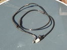
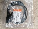
brake sensor cable7 views
|
|
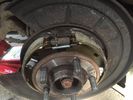
Thread upload8 viewsImage uploaded in thread 147264
|
|

Thread upload43 viewsImage uploaded in thread 137607
|
|

Black Deposits to interior of Brake Light Switch2862 viewsThere are two contacts, one on each side of the vertical plunger under the copper metal. The set of normally open contacts on the left side that carries the power for the brake light filaments, (15 amp fuse F15P), is apparently not heavy enough as the contacts deteriorate and generate the black residue.
The set of normally closed contacts on the other side appear to be sized OK. There is not as much current, (5 amp fuse F66P), flowing thru the contacts to the ABS module, however the contacts are likely adversely affected by the black residue produced by the other deteriorating set of contacts.
One presumes/hopes that the newer replacement switch now has contacts heavy enough to carry the brake light power. It would be ideal if the ABS set of contacts were sealed from the brake light contacts to prevent contamination of the normally closed set of contacts.
|
|

Brake Light Switch, Find, Remove, and Install Instructions 7853 viewsThis is a two page doc outlining where to find the brake light switch, how to remove it, and then install the new one.
Note, do not move the brake pedal when removing or installing the switch. Let the brake pedal hang where it wants to. The switch design is actually cunning, and as such is supposed to make the removal and install fool proof. Hence if you think too much about it, you can wreck the new switch.
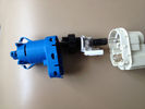
If you want to inspect the interior of the switch, wait until you have removed the old switch. You can then just unsnap the blue from the white to get it apart. Inside, the switch is quite simple, (no circuit boards), but it will probably show black dust from failing contacts.
I think the reason the switch fails is that the Normally Open, (NO), contacts of the brake light contacts were made too light to carry the current load for make and break of the tail light filaments. I also think the black dust created then fouls the Normally Closed, (NC), second set of contacts for the ABS circuit. As such, the Normally Closed contacts become intermittent in operation and display as a fluctuating open and closed circuit condition to the ABS system when the ABS should be seeing a steady closed circuit. Hopefully the replacement switch contacts are more robust and may be as I recently replaced my switch again just as a matter of maintenance. While in a redesign, ideally the NC contacts should be sealed or at least separated from the NO contacts, when I inspected the removed switch, this time there was no black dust present.
Probably the removed switch will have a Land Rover oval logo moulded into it, the new one, FOMOCO.
|
|
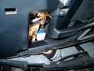
Brake Switch Visible thru Opening4975 viewsThe blue and white bit is the switch; the sort of gold appearing box,(it is really black), you will not see in your 3 as it is a Smooth Talker brand amplifier for my Blackberry phone antenna. This install is detailed in the SmoothTalker phone antenna section of my gallery.
One way to remove and install the switch is to lower the "horizontal" panel above the brake pedal as shown where the flashlight head is located. To actually remove the switch, you slide your hand thru the gap and rotate the switch clockwise 1/4 turn while watching thru the rectangular opening. Installation of the new switch is the reverse of above - 1/4 turn counterclockwise.
Before you remove the switch, note its orientation - horizontal with electrical wires to the left. That is the way it should look after replacement as well.
The second time I replaced the switch, I did it all thru the rectangular opening and did not remove the horizontal panel - that is experience helping out.
The knee kick you have to remove regardless. It is sort of hinged at the bottom so you just pull at the top and sort of rotate the knee panel and then pull upwards for two plastic "fingers" to clear the slots they reside in.
|
|
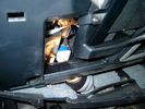
Smooth Talker Amplifier Box mounted below near steering column.179 viewsThe gold look box due to the lighting, (actually black), is the antenna amplifier located near the steering column. It can be put anyway but this seemed an OK location as I ran the antenna connector cable rearward from here to the back corner of the 3 and then up to the underside of the roof glass at the rear. The blue/white thing is the brake light switch that often must be replaced. See the Brake Light Switch file within this Gallery regarding the switch replacement.
|
|

Black Deposits on Brake Light Switch Plunger2758 viewsThis jpg I got off another forum and is typical of what one will see when one opens up the removed brake light switch. The black powder is residue from arcing of one of the pair of contacts within.
Hopefully the newer switches with the FOMOCO logo moulded into the plastic are improved from the Land Rover logo marked early units, however I doubt it.
The Ford part number is SW-6572 and/or 7E5Z-13480-A as used on the 2006 to 2009 Ford Fusion's and Mercury Milan's; the Land Rover part number is XKB500110. Cost of switch could be about twenty five dollars. A previous LR part number for the switch was XKB500030, so hopefully the newer LR part number, XKB500110, reflects some improvement in reliability.
It is possible that the new switches are better as I installed a replacement 72,000 km, (45,000 miles) later, at 195,000 km (121,000 miles). When I took the removed switch apart to inspect, it was clean inside. There was no black dust - the switch looked like new, hence they must be improved now.
|
|

7727 views
|
|
Thread upload9 viewsImage uploaded in new thread
|
|
Grommit21 viewsIs this a free grommit low down and on the LHS of the brake servo?
|
|
62 views
|
|
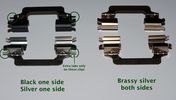
Front brake clips23 views
|
|
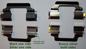
Front brake clips21 views
|
|
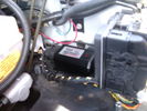
CounterAct Power Supply mounted 247 viewsPicture is blurred, however power supply is 3M two sided tape to the flat black plastic of the second battery compartment just under the antilock brake pipes to the fender side of the brake fluid reservoir. The white wire to the left rear coupler pad runs thru the firewall hole near the steering column. The blue wire to the right front coupler runs across and above the engine following the other wiring looms that cross the vehicle.
|
|
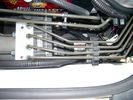
CounterAct Power supply mounted under brake lines.194 viewsThis top view shows where I located the power supply. It is attached with 3M sticky to the black plastic surface that is located under the brake lines.
When the system is operating properly, the red LED pulses about twice per second.
Some users claim they can hear a very slight hum or whine coming from the unit. My unit seems silent.
|
|
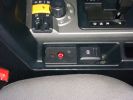
81 views
|
|
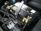
2nd battery in engine bay. Look under the rigid brake lines to see the solenoid438 views
|
|

Thread upload6 viewsImage uploaded in thread 139074
|
|
Thread upload22 viewsImage uploaded in thread 167901
|
|

Collection of EPB instructions & PDF\'s of Brake Posts659 viewsAll you need to change your brake pads or Brake Disks as well as adjuusting the Electronic Parking Brake. Includes the bedding in process for EPB pads
|
|

67 views
|
|

64 views
|
|
Thread upload18 viewsImage uploaded in new thread
|
|

D3_Brake_Switch25 views
|
|

114 views
|
|
Thread upload5 viewsImage uploaded in new thread
|
|

Thread upload8 viewsImage uploaded in new thread
|
|
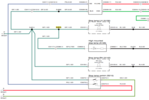
D3_Hi-Level_Brake_Splice15 views
|
|
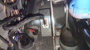
Electronic Relay156 viewsRelay mounted to mounting frame of the brake pedal
|
|

63 views
|
|
186 views
|
|
233 views
|
|
233 views
|
|
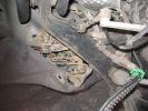
Brake sensor connector ( with 2 red wires connected)302 views
|
|
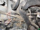
plenty of room once you pull the inner arch back out the way314 views
|
|
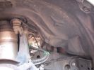
pull out the 3 clips circled in red300 views
|
|

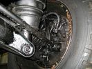
OSR_Brake47 viewsFriction material loose and broken off.
|
|

Thread upload5 viewsImage uploaded in thread 150447
|
|

Thread upload5 viewsImage uploaded in new thread
|
|

Thread upload2 viewsImage uploaded in new thread
|
|

Thread upload12 viewsImage uploaded in new thread
|
|

Thread upload3 viewsImage uploaded in new thread
|
|

Thread upload6 viewsImage uploaded in new thread
|
|

Thread upload28 viewsImage uploaded in new thread
|
|
Thread upload1 viewsImage uploaded in thread 209269
|
|
Thread upload17 viewsImage uploaded in thread 151102
|
|
415 views
|
|
Spyder LEDs with brake (Sorry for the blurr)165 views
|
|
A rapid halt forces the disco 3 drivers to use their doors as airbrakes245 views
|
|
The Road I came up.333 viewsThis is the road which caused my problem, drove up it, not realising there was a T junction which I had to turn right, turned, but could not get myself to get off the brakes and accellarate, so went straight on down a ditch!
|
|
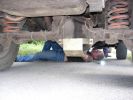
Rob removes Chris handbrake linkage after fire151 views
|
|
clearout dual brake light looms0 views
|
|
173 views
|
|

D5 Emergency Hanbrake Release46 views
|
|

Thread upload28 viewsImage uploaded in new thread
|
|
Thread upload8 viewsImage uploaded in thread 130185
|
|

Park Brake wiring103 views
|
|

Thread upload2 viewsImage uploaded in thread 186327
|
|
Thread upload25 viewsImage uploaded in thread 109204
|
|

Thread upload21 viewsImage uploaded in thread 109204
|
|
Thread upload1 viewsImage uploaded in new thread
|
|

Thread upload12 viewsImage uploaded in new thread
|
|
Thread upload5 viewsImage uploaded in new thread
|
|
Thread upload0 viewsImage uploaded in new thread
|
|

113 views
|
|

high level brake light removal544 views
|
|
Thread upload27 viewsImage uploaded in thread 91299
|
|
Faith in the handbrake !179 views
|
|

brake vacum pump recall42 views
|
|
623 viewsEmergency hand brake cable (loop)
|
|

Brakes 19 views
|
|

Brakes 36 views
|
|

Brakes 911 views
|
|
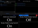
D3 Ian Brake On Off15 views
|
|
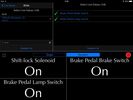
D3 Brake On11 views
|
|
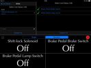
D3 Ian Brake Off13 views
|
|

Brakes 27 views
|
|
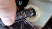
Brake fluid test12 views
|
|

Brakes 38 views
|
|

Brakes 510 views
|
|
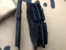
Brake pads worn26 views
|
|

Brakes 56 views
|
|

Brakes 65 views
|
|

Brakes 76 views
|
|
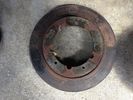
Brake disk 30 views
|
|

Brakes 811 views
|
|

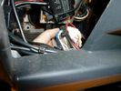
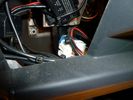
Switch is blue colour thing thru the rectangular opening.3177 viewsThe blue coloured plastic bit thru the rectangular opening is the brake light switch. The fist time, I found it easier remove the switch by dropping the horizontal plastic panel, (two screws), and then slipping my hand in and rotating the switch clockwise 1/4 turn. The second time, I was able to remove the switch thru the rectangular opening and did not need to remove the horizontal lower panel. Obviously, I had to remove the sloping knee pad panel, (note sort of hinged at the bottom so pull back from the top.)
Regardless, do not touch the brake pedal - just let it sit where it wants to. One has to first remove the angled knee pad panel that sits under the steering wheel. It can be pulled from the top corner at the door side. Pulling releases a pair of those U shaped metal clips that LR loves so dearly. You have to pull quite hard. The bottom is held by a couple of plastic fingers in a couple of slots so you pull at the top till the two clips release and then rotate the panel and pull upwards a bit.
To remove the switch, you rotate it clockwise and pull outwards. Rotating the switch clockwise automatically retracts the plunger back into the switch body away from the brake pedal arm.
Similarly when you install the new switch, the required 1/4 turn anti clockwise rotation action releases the plunger so it lays up against the brake pedal arm and at the same time, secures the switch in place.
To remove the electrical wires, the switch will drop below the horizontal pad and hang from the wires so unclipping the electrical connector plug is fairly easy to do.
|
|
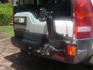
Broken Rear Wheel Carrier197 viewsThe Opposite Lock rear wheel carrier. Vertical weld adjacent to brake light has broken
|
|
Rest stop after our first hill descent.191 viewsMode: TR Rock Crawl with HDC turned off as I found that the ABS kicked in too much. As we were in convoy I maintained a safe distance from car in front and just "feathered the brakes" as suggested by an instructor.
|
|
![Filename=IMG_0188[1].jpg
Filesize=118KB
Dimensions=1280x960
Date added=19.Jun 2010 IMG_0188[1].jpg](albums/userpics/15526/thumb_IMG_0188%5B1%5D.jpg)
Brake Sensor145 views
|
|
231 viewsLED\'s instead of ordinary bulbs, brake applied
|
|
Brakes fitted122 viewsBrakes easy to fir - sensor replacement less so.
|
|
Old Brakes109 viewsOld brakes past their best.
|
|
Are you sure I must not touch them brakes??? (HDC!)164 views
|
|
2 viewsFront Brake sensor
|
|

Hand Brake Cable Hanger9 views
|
|
Hand Brake Cable Hanger6 views
|
|
wheel, brakes and air bag1011 views
|
|

New rear brakes24 views
|
|
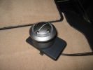
This is the controller unit that I attached to the emergency brake pop-out plate.386 views
|
|
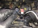
EGR replacement14 viewsWhile doing stuff on the engine. Good idea to clean yer MAF. Brake cleaner and air used to get it clean again
|
|
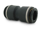
John Guest DOT all plastic fitting718 viewsThis is a picture of the John Guest DOT all plastic union. If you look closely, you can see the DOT imprinted in raised letters on the end of the fitting. This is of a 1/4" connector rather than the 6mm that the 3 requires.
The picture is similar to the air suspension pneumatic fitting union that Land Rover sells as replacement part # STC8580. This is for 6mm OD tubing size. The STC8580 comes with what are called "Collets" at each end that cover up the press to release feature underneath. See the John Guest web site www.johnguest.com under the Pneumatics section and also in Downloads for their catalog for install and remove instructions.
The actual "air brake spec" fitting that Land Rover provides has an interior 4mm OD ferrule that slips inside the 4mm ID of the nominal 6mm tubing. I have not yet been able to obtain the John Guest part number for the LR fitting, only the LR part number. This part number was generated for the RR Classic air systems.
|
|

John Guest (LR part # STC8580) push in straight 6mm tubing to tubing connector730 viewsThis picture is similar to the air suspension pneumatic fitting union that Land Rover sells as replacement part # STC8580. This is a 6mm OD tubing size push in to install straight tubing to tubing fitting. The STC8580 comes with what are called "Collets" at each end that cover up the press to release feature underneath. See the John Guest web site www.johnguest.com under the Pneumatics section and also in Downloads for their catalog for install and remove instructions.
The actual fitting that Land Rover provides has an interior 4mm OD ferrule that slips inside the 4mm ID of the nominal 6mm tubing. Hence the fitting depicted and part number are not actually correct. I have not yet been able to obtain the John Guest part number for the LR fitting.
The fittings that show in this doc are what I call food service fittings rather than transportation or Air Brake fittings. The part LR sells, (STC8580), is the Air Brake type for transportation.
|
|
![Filename=kit380-discs-pads-calipers-carriers-front-brake-overhaul-kit-kit-all-discovery-3-2_7-4_0-1231428-p[ekm]270x250[ekm].jpg
Filesize=21KB
Dimensions=270x250
Date added=25.Sep 2018 kit380-discs-pads-calipers-carriers-front-brake-overhaul-kit-kit-all-discovery-3-2_7-4_0-1231428-p[ekm]270x250[ekm].jpg](albums/userpics/33392/thumb_kit380-discs-pads-calipers-carriers-front-brake-overhaul-kit-kit-all-discovery-3-2_7-4_0-1231428-p%5Bekm%5D270x250%5Bekm%5D.jpg)
Thread upload11 viewsImage uploaded in new thread
|
|

LR Electric Trailer Brake C2590 Female Connector606 viewsThis female connector, C2590, located up above and near the brake pedal is for the Trailer Electric Brake Controller hookup.
The Black wire in the bottom right is pin #3, the ground. The Blue wire to the left is pin #6, the Trailer Brake Controller output going to the rear trailer socket.
The White #4 wire is the 30 amp fusible link, (Link 6E in the engine compartment junction box), for the Brake Controller 12VDC power feed from the battery. Note that this would make a pretty good power source for CB radios and the like if no electric trailer brakes were required.
Pin #5 is a Green wire from the stop lamp switch, (the control input for the Brake Controller).
This plug is standard on all NAS (LR3) vehicles, but unlikely to be found on the D3 spec units.
|
|
Thread upload0 viewsImage uploaded in thread 203557
|
|

NAS 7 Blade Round plus NAS 4 Pin Flat Vehicle end Socket528 viewsThis shows the function of each blade when looking into the connector at the vehicle end for the 7 pin NAS plug. The layout is the pin order for most new North American pickup trucks and the LR3/4.
The colour and gauge of the wires feeding into the back of the plug varies even within manufacturer model lines.
Also detailed is the flat 4 pin layout common on smaller trailers not having electric brakes. This includes most U-Haul rental trailers.
|
|

Wheel cut thru definitions and specs898 viewsNote the location of REAR SPACING and also OFFSET; probably two of the most important dimensions and not always understood as related to wheel size and relationship to the brake components.
For the 3, Rear Spacing is approximately 6.5 inches or 165 mm for a nominal 8" rim. Offset is 53P or 53mm Positive, which means the distance from the machined hub flat mounting surface to the rim's true centreline is 53 mm in the outboard direction. (The rim illustrated has a negative offset.)
As Positive offset increases, this means the wheel wraps around the disc brake mechanism more deeply, and hence the more the wheel would cover the brake parts. This is why most 18" wheels will not fit with the larger Brembo "supercharged engine" brake calipers.
Pitch circle diameter is 120mm; Pattern is 5 lug, and the tyre load rating is 112 with a recommended tyre speed rating of H or higher along with the XL load rating. For the 3, the stock tyre diameter is about 30 inches. The 255/60/18 or 255/55/19 OEM tyre outside diameter is 30.04 inches; Wheel lug torque is from 130 to 150 Nm or 96 to 110 lbf-ft and the lug nut hex socket size is 22mm.
Max Load High Speed Driving Tyre pressures are Front, 33 psig, (230 Kpa) and Rear, 42 psig, (290 Kpa).
The OEM rims are rated at 940 kgs, the highest that LR makes, hence while rims from other Land Rover products may physically fit, the odds are they are under rated in a weight sense.
|
|

lr3-kaymar-closed with 20"405 viewsthe kaymar carrier, designed to allow two tires, sets them both a bit outboard, thus blocking the lamp. that\'s when I realized why they put the fully functional lamps in the bumper (functions: running, brakes, signals, hazard)
I plan to re-weld the locating section more towards the middle of the rear similar to Disco II orrientation.
|
|

solo steep gravel stop = park brake plus reverse on shifter333 viewsso our disco II\'s locked all 4 wheels with brake but now the modern lr3 slides away with only the park brake!!!! 1. put auto shifter in reverse (low gear) with foot on brake, 2. apply park brake, 3. get out and snap photo incase something fails and it slides away ;)
I reversed up the hill from this position, system decided to engage extended heigh mode for some reason trying to gain traction on loose surface.
|
|

Excel file for Rotors and Brake Pads part numbers for 4.4L V8 petrol LR3769 viewsComparing the cost of the various brands of brake parts is time consuming. Once you have your parts costs, this little spreadsheet will make collating the info easier.
I did not make any provision for labour costs, but the file can be downloaded and then modified. You can change Dollars to Euros or Pounds or whatever and insert lines for labour costs as desired.
Do not pay too much attention to the $ numbers as they are a mix of US and CDN, and from differing time frames, (prior to Spring 2011) . Also the brake part numbers are for my 2005 North America spec LR3 with the petrol 4.4L V8; diesel powered and supercharged 3's may have different part numbers
|
|

Land Rover Brake Light switch XKB5001102700 viewsThis is what the switch looks like when removed from the parts box. Note that the plunger is recessed back into the body and when installing, the process of rotating the switch body 1/4 turn anticlockwise releases the plunger so it pops longer and engages the brake pedal. If you look down on the plunger you can see curved slots where the rotation takes place.
Do not try to rotate the new one - play with the one you remove. Also do not press on the brake pedal when removing or installing as you will damage the plunger - this is one of the reasons the plunger is retracted into the body for installation. It is also for this reason that if you try to confirm the operation of the switch contacts with an ohm meter by pressing the plunger, the switch will appear not to function as one might anticipate. Have faith, the switch will however, once installed and the plunger is in full motion.
|
|

LR3 Brake Wear Sensor Wiring1517 viewsThis 1 page wiring diagram pdf shows that both the front and rear brake pad wear sensors are part of a closed series circuit to ground.
In operation, when all is good, the series circuit is grounded and the amber brake wear warning indicator on the instrument panel is not illuminated.
When the pads on one wheel, either the left front, or right rear, become too worn, the respective sensor is "cut" which results in an open circuit condition. This causes the dash brake wear indicator to illuminate.
The circuit is like the old style Christmas light strings where one burned out bulb caused the whole string to go out.
A quick field fix to get the dash light to extinguish in lieu of replacing the sensor and pads etc is to disconnect the brake pad wear sensor and short across the two open conductors of the vehicle side connector plug. This of course means you now have a normal vehicle, one of the thousands that do not feature brake pad wear information systems.
|
|

Stop Light Lamp Circuit pdf2492 viewsThis pdf shows the brake light circuit for the NAS LR3.
Note that power for the brake light bulbs can come either thru the brake light switch power feed /contacts plus also from the Hill Decent Control, (HDC), system relay located within the Central Junction Box, (CJB) - yes two separate sources of power for the brake light bulbs. This would tend to explain how a brake light circuit concern shows up as a hill decent fault message; also why lesser vehicles without hill decent braking mechanisms, (HDC), never display this sort problem when a brake light bulb or switch acts up. You never have a problem related to a system that does not exist.
Additional evidence of the relationship of the HDC and the tail light circuit is demonstrated by when the HDC actually acts to slow the 3 down, the brake lights automatically illuminate even if the slowing action was merely retarding the engine speed or shifting to a lower gear, (in other words, no foot on the brake pedal).
There is also a tie in to the Cruise Control and hence a failing brake light switch can affect cruise operation or just create false Cruise Control messages. To further complicate the issue, while there are no messages generated, operation of the radiator electro viscous fan can also be negatively affected by the fouled set of secondary contacts within the brake light switch. This is all because the NC contacts within the brake switch send misleading messages to the ECU.
While the ground wire design is similar to other vehicles, note the grounds for the brake light filament and the reverse light filament are common on each side. That means that if one has a non functioning brake light on one side, the reverse light may not also work or that some problem with the reverse lights could back feed into the brake lights. This situation while unusual, can result when grounds are corroded probably due to swimming in rivers and creeks or just routine driving in a marine environment.
|
|

LTB00145 - Technical Bulletin - Remove & Install Parking Brake Cables90 views
|
|

LTB00189 - Technical Bulletin - Remove and Install Parking Brake Actuator103 views
|
|

LTB00205 - Technical Bulletin - 'Chirp' or 'Squeal' Noise from Rear Brakes81 views
|
|

LTB00354 - Technical Bulletin - Parking Brake Shoe Lining Adjustment130 views
|
|

66 viewsThe cover that you remove to access the cable, for manual release of the electronic parking brake.
|
|

NAS 7 plus 4 pin LR3 Trailer wiring, battery end. 549 viewsThis is the LR wiring diagram from the engine compartment battery location to the Electric Brake Controller connector, C2590, located under the dash near the brake pedal.
|
|

NAS 7 plus 4 pin LR3 Trailer wiring, trailer end. 498 viewsThis is the LR wiring diagram showing the conductors from the the Trailer Brake Controller connector, C2590, back to the rear combo NAS 7 plus 4 pin sockets.
|
|
Thread upload3 viewsImage uploaded in new thread
|
|
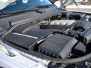
Overview of engine compartment from Main Battery side, (Passenger, LHD), looking across to Aux Battery753 viewsNote labels on main battery cover. The one you cannot read says that an auxiliary battery is installed on the other side. This is to warn service people should they wish to shut off all battery power.
The main starting battery is supposed to be of CaCa separator construction and DIN H8 or BCI Group 49 size. This means Calcium separators Wet Flooded Lead Acid, 13.9" long, 7.5" high and 6.9" wide.
On the Aux battery cover is a label saying to disconnect the blue Anderson single pole connector located under the cover by the brake reservoir. BCI Group 40R battery is small enough that the cover goes back on.
|
|
Replacing Rear Brakes Etc.80 views
|
|
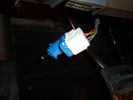
brake light switch3655 views
|
|
brake light switch3216 views
|
|
brake light switch2210 views
|
|
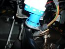
brake light switch3663 viewscommon failure, replace with newer one marked fomoco
|
|
firewall plug run855 viewsThrough the firewall to the right of the brake master cylinder. On left hand drive, this hole would be closest to the outside edge of vehicle.
|
|
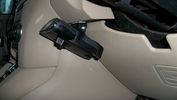
P3 brake controller 198 views
|
|
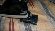
P3 brake controller mount 288 views
|
|
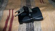
P3 brake controller mount 384 views
|
|
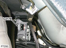
C2178 Module-Parking brake172 viewsPart No.: YPC801020
Colour: BLACK
Cavities: 32WY
Harness: CHASSIS HARNESS
Location: Beneath center of vehicle
|
|
Brake Pads @ 47,600 klms86 views
|
|

Worn Brake pads33 views
|
|

44 views
|
|
Thread upload29 viewsImage uploaded in thread 91299
|
|

parking brake and actuation61 views
|
|

182 views
|
|

EPB Adjust Feb 2011122 views
|
|

93 views
|
|

Thread upload4 viewsImage uploaded in thread 150447
|
|

Thread upload8 viewsImage uploaded in thread 150447
|
|

Thread upload2 viewsImage uploaded in thread 150447
|
|

Thread upload4 viewsImage uploaded in thread 150447
|
|
Thread upload1 viewsImage uploaded in thread 177571
|
|
Thread upload4 viewsImage uploaded in thread 177571
|
|

16 views
|
|

Thread upload24 viewsImage uploaded in thread 52130
|
|

EPB wiring diag46 views
|
|

Thread upload2 viewsImage uploaded in new thread
|
|
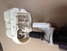
Brake Light Switch Guts - Black Soot47 views
|
|

handbrake works well31 views
|
|
Polar Foil Handbrake135 views
|
|

Workshop manual page - brakes28 views
|
|
181 views
|
|

Brake servo recall work - new pipework121 viewsThis is the new visible result of the recall work just done
|
|
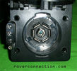
NAS 7 pin + NAS 4 pin Flat Trailer Socket308 viewsThis is the vehicle end of the NAS trailer harness that is located behind the removable plate centered within the rear bumper by the towing loop. Re the four pin flat connector, from the bottom, the exposed bare lower pin is the ground, usually the White wire on a NAS trailer. The next pin up is normally a Brown wire on a trailer and is for the Tail Lights. The third pin, normally a Yellow wire, is the left signal light; the top pin, normally a Green coloured wire, is the right signal light.
Re the round connector, from the notch in the plastic surround, clockwise, the first blade is ignition controlled +12VDC battery power, (only alive when engine running), and on the Land Rover factory harness is an Orange wire; on a NAS trailer, usually Red but perhaps a Black wire.
Next blade clockwise at 3:00 o'clock above, is the Right Turn signal light, a Green wire on the LR harness, and also on a NAS trailer.
At 5:00 o'clock, the next blade is for the Electric Brakes and is Blue on both the LR harness and on a NAS trailer.
The Ground wire is next, White on both the LR harness and on a trailer.
At 9:00 o'clock above, is the Left Turn signal, Yellow on both the LR harness and on a trailer.
The last blade to the left of the line up notch is the Tail Light circuit. On the LR harness, the wire colour is Brown with two White stripes and on a NAS trailer, Brown.
The centre pin is for the Reverse Back Up lights and is Black on the LR harness and often Purple on NAS trailer wiring but can be Black also.
Note that when the socket assembly is installed on the 3, the notch in the plastic surround is on the left - that is rotated 90 degrees anticlockwise to the picture above. In other words, When installed on the 3, the 4 pin flat connector lays horizontal and is located below the round socket.
|
|
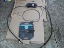
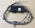
384 viewsOverview - box, two brake cables and release cable
|
|
Brake pipe72 viewsCorroded where the clip had held it on
|
|
Thread upload10 viewsImage uploaded in thread 174619
|
|
25 views
|
|
Brake lights on353 views
|
|

Brakelight Switch26 views
|
|
Gareths stuck park brake257 views
|
|

Tekonsha Ford Brake Controller Adapter part number 3035-P275 viewsThis is the adapter cable between the Brake Controller and the existing C2590 female plug located near the brake pedal on NAS spec LR3's. The flat 4 pin plug of the adapter cable connects to the Controller; the rectangular 6 hole male plug to C2590.
There are only four conductors in the adapter cable, but one will see five pins within the Land Rover C2590 plug. The #2 pin is not required for the NAS setup. #2 pin is the circuit between the head lamp switch and vehicle side running lamps required in the civilized world.
The single pin at the bottom in the picture is #3 and on the Land Rover, a Black wire tied to ground. The other pin at the bottom and across to the left is #6, and Blue on the Land Rover. This is the Brake Controller output to the trailer socket at the rear.
#4 is the pin at the top left, and is a White coloured wire from the battery. Pin #5 is from the stop light switch, and is Green on the Land Rover.
Note that the adapter cable colours do not necessarily follow all the above referenced Land Rover colours.
|
|

Tekonsha P3 Brake Controller 90195 to Ford 3035-P wiring adapter plug311 viewsThis two page pdf is the general instruction for hooking up the Tekonsha part number 3035-P adapter cable between a Tekonsha P3 controller and the existing Land Rover/Ford plug, (called C2590 in the Land Rover wiring diagrams), that is hidden above the brake pedal.
The "Ford" plug, (C2590), is grey and is stuffed up above the brake pedal arm.
Mount the P3 controller appropriately and then connect one end of the custom cable to the P3 and the other to the "hidden" plug.
You will now have power for your trailer electric brakes in the round socket at the rear of your LR3; also no computer update from the Land Rover T4 unit is required. For once, it is plug and play.
If however, your trailer has LED tail lights, you may have trouble with the flashing of the trailer signal lights or non recognition by the 3 that a trailer is connected. As such, the little green trailer signal will not illuminate when a trailer is connected and the signal lights are used. This can affect the shifting of the transmission and much to your annoyance, the backup sensors will still be functioning rather than being auto disabled.
|
|

Tekonsha P3 Electric Trailer Brake Controller model 90195291 viewsOne model of electric brake controller that is commonly used on the LR3 is the Tekonsha P3 unit, model number 90195. It mates up to the LR3 with a custom "Ford" adapter cable, Tekonsha part number 3035P. No wire cutting or splicing is necessary - just mount unit and plug adapter cable in.
|
|
Thread upload3 viewsImage uploaded in new thread
|
|
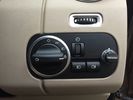
Brake Controller dial19 views
|
|
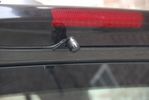
Rear view camera123 viewsRear view camera mounted to the center brake light. It produces a mirrored image. The camera is placed just a little of center to allow it to see the tow hook. When placed in the exact center the view on the tow hook would be blocked by the rear screen whiper
|
|

Burnt Brake Rotor13 views
|
|

Vehicle Maintenance Log for LR3/4 D3/4 or other1135 viewsThis is a Excel file that you can download and then modify to suit. It is very simple, but allows me to keep track of most maintenance and fixes etc on my LR3. All columns and rows and boxes can be edited.
I did not erase any data in the various boxes so you could see how I am using it - again not very fancy but it works for me. Under the brakes column, one will see f6 r5 which is how I keep track of the condition of the brake pads. The dealer records the pad thickness at each oil change so that is where the numbers come from.
f is for Front Pads, 6 is for 6mm; r is for Rear pads, 5 is for 5 mm. New pads are about 10 mm; replacement is at 3 mm or less. The amber coloured brake wear dash warning light should come on at about 2 mm.
|
|

electric plugs RRS inside wing behind rear brake light5 views
|
|

D3 plugs in inside wing begind rear brake light8 views
|
|
|
|
|
|