| Search results - "battery" |
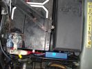
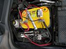
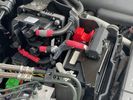
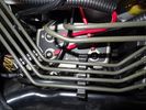
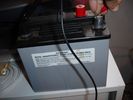
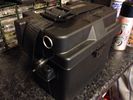
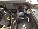
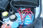
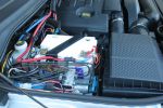
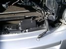
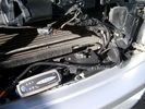
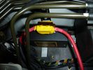
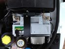
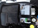
139 viewsThe weatherproof junction box fits neatly down the front of the battery, all contained inside the battery box.
|
|
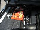
414 viewsDualBattery 80ampH
|
|

Estrarre il circuito stampato con la batteria - Exctact the printed board with the battery18 viewsRimossa la parte superiore del contenitore, estrarre il circuito stampato sollevandolo leggermente dalla parte della batteria.
Removed the top of the box, pull out the printed circuit board slightly lifting from the battery side.
|
|
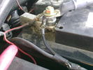
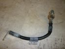
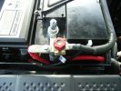
battery neg connection149 views
|
|

12v Battery SoC Table89 views
|
|

Thread upload10 viewsImage uploaded in new thread
|
|
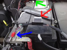
2 FBH Loom77 views
|
|
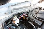
114 viewsBattery to battery cable in place along edge of engine bay
|
|
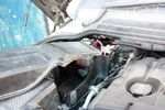
120 viewsModified aux battery box cover with shape of battery to battery cable. I also removed the tab which was fouling my traxide brain mounting bolts.
|
|
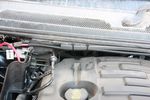
97 viewsBattery to battery cable tied to edge
|
|
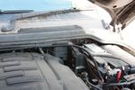
111 viewsBattery to battery cable in main battery box
|
|
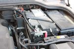
113 viewsBattery to battery cable attached to main battery
|
|
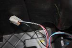
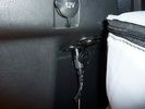
109 viewsThis is the plug for the accessory socket at the rear of the cubby box. On commercial D3 such as this one, there is no accessory socket so this plug is unused. I tapped into the 12V wire as an ignition feed. This will feed a relay coil which opens up power from the aux battery. Like this I can still retro fit and make use of the accessory socket later on.
|
|
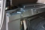
91 views12V socket done. This is permanently powered by the Aux battery. Another one was done on the other side, though that one required drilling the hole with a 29mm hole saw as there wasn't an unused hole on that side.
|
|
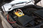
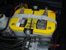
125 viewsOptima Yellow Top in battery box. This is the version with side terminals so there will be some modifications to be done to fit
|
|
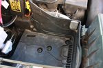
112 viewsDue to the side terminals protruding out the side and affecting the battery clamp, I found the battery will fit better if it could be pushed a few millimeters towards the engine. This lip will have to be removed.
|
|

91 viewsBattery clamp needs to be modified due to the mouldings on the battery top to the side terminals. All that is needed is to cut off the bit as seen.
|
|
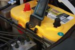
115 viewsModified battery clamp test fitting on battery.
|
|
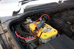
131 viewsBattery clamped down, terminals and cables attached
|
|
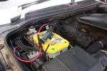
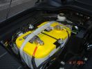
131 viewsAll done. Added some cable sleeving to avoid cables rubbing against battery clamp
|
|
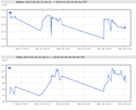
Battery226 viewsInterstate vs Deka = DEKA Do not buy interstate batteries.
|
|

big jeep28 viewswent to collect my optima battery...this was in getting a new wing fitted
37" wheels are quite big...
|
|
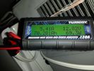
battery consumtion357 views24 hour power usage of an Engel 32L + NL 72L at 1c & -18c freezer in 80-92 degree heat in the shade. That's about 70amp hours.
|
|
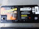
Deka 9A49 AGM Intimidator327 viewsThe Deka 9A49 AGM Intimidator makes an excellent primary battery alternative to the factory or Interstate. Made in US of premium quality. This is an excellent match with the Traxide system w/another Deka or Yellow Top optima.
This will behave properly in your D3/4 LR3 with slightly less wear and tear on your alternator.
|
|
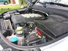
Winch Power upgrade319 viewsUsing 2 warn kits, and removing one of the wires to use on another project. The purpose was to replace the power and ground wire. I used Warn kits, which are 4/0 Welding cable. The original red #4 warped from getting a little too worn. The 2nd
Battery #1 Deka 9A94 AGM Intimidator, Battery #2 Deka 9A47 AGM Intimidator WARN 36080 28" Quick Connect Cable X 2, WARN 26405 Quick Connect Cable 7' X 2, WARN 15901 Black Cable X 1 -- winch control 72" X 1 https://www.facebook.com/DifferentialPartsUS
|
|
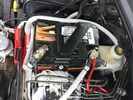
Wiring342 viewsThis is the final wiring configuration. It shows the dual battery wiring, 75A wiring run to the boot, the winch and in the lower right you can see a few turns of coax with a snap on ferrite near the base of a VHF Antenna.
|
|
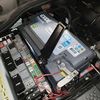
new battery, exide EA1000 / 100Ah/900A7 viewsImage uploaded in thread 177818
|
|
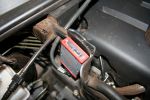
TT Box Location146 viewsSmall TT box, easy to fit on spare battery compartment
|
|
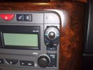
position of buttons for Parrot phone102 viewsthis can be put basically anywhere as it connect via bluetooth to the rest of the system. It is self powered (lithiam battery in it) so just stick it anywhere with no requirements for finding a live wire etc
|
|

Alternator and Regulator Wiring Diagrams, TDV6 and petrol V8 and V61989 viewsThis is a three page pdf that shows the alternator and regulator wiring for the petrol V6, petrol V8 and TDV6. The pdf can be either printed or by right clicking on the displayed pdf, rotated as required for viewing.
Of interest is that the regulator gets its instructions primarily from the Engine Control Module (ECM) and only secondarily from the vehicles electrical buss. The conductor from the battery thru the 5 amp fuse F20E is to provide initial power to excite the alternator at startup and then secondarily, to instruct it if the PWM signals were not available. Primary instructions to and from the ECM are thru the two other conductors via a digital like Pulse Width Modulated (PWM) signal.
If F20E, the 5 amp engine compartment fuse box fuse is blown, the red alternator light on the dash will be illuminated. This means that the alternator could be OK, but if the F20E fuse is blown, no electricity will be generated. Hence check the F20E fuse if you get a red ALT light or some indication of the alternator not working.
Regarding operation of the red ALT light on the dash, it is not the regulator within the alternator that tells the red light to illuminate, or not, but instead the ECM. This is the reason the red light does not function in the same manner as with older vehicles. With the 3, sometimes you have illumination and sometimes not depending upon what the ECM is thinking. What this means is that you can have an alternator that is failing but the red light does not illuminate as the ECM is compensating for reduced alternator output - maybe by draining the battery and or cutting back on vehicle electrical loads such as shutting off or cycling the radio amplifier or heated seats.
|
|
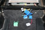
04278 viewsThe green wiring harness is the speaker outputs. Green is + and Green with white stripe is -. We tested all the wires with a 9V battery to figure out which went to what speakers then clearly labeled them as we did.
|
|

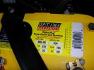
Optima Battery Specifications168 viewsOptima Battery Specifications
|
|

Battery 25 views
|
|
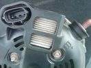
Alternator Plug and B+ terminal919 viewsPictured is the rear of the older Land Rover part # YLE500190 alternator showing the shiny cooling fin of the Regitar VRH2005-142 regulator under.
The first pin in the far left side of the connector is numbered #1 in the LR electrical wiring diagrams and is Battery Voltage Sensing (BVS); the middle pin, #2 receives a Pulse Width Modulated (PWM) signal from the Engine Control Module (ECM), and the right pin, #3 carries a PWM signal back to the ECM. Terminal Pin #2 on the LR wiring diagrams is called Alternator Control or ALT CON; Pin #3 per LR is called Alternator Monitoring or ALT MON.
Pin #1 is similar to what in older designs used to be called A or Batt, but is now called by Denso, S, AS, or Alternator Sensing for this design. Pin #1 also provides power to excite the alternator at startup until the PWM instructions over ride the battery voltage info. Land Rover calls the electronics under the pins a Smart Regulator, ironic, as it has to follow orders from the ECM rather than give the orders - new age thinking I guess. This is different from older design internal regulators that look at just the battery or the electrical buss voltage and then decides itself what to do.
It is almost like we are back to the external regulator designs of old, except that the ECM may decide that instead of telling the alternator to make more power, to load shed, and hence shut down the heated windscreen, seats, or whatever other electrical loads it decides are appropriate. My view is that the "smarts" are in the ECM and that the "regulator" should be regarded if not dumb, then as being a slave to the ECM.
|
|

amps-acid-car-battery-soc-charge-voltage-3d26 views
|
|
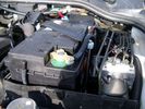
Aux Battery showing ground cable bolt "upside" down 1577 viewsIn order to obtain sufficient height clearance to get the plastic cover back on, I had to install the ground cable to the underside of the battery post connector.
Note the battery vent hose, (approx 5 ft required) is run down into where the windshield washer fluid container is located. There is not much electrical or metal in that area to be corroded by battery gas plus the open end of the vent hose tends to be protected from dirt and stays clean as well.
|
|
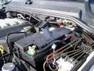
BCI Group 40R Deka 640RMF battery showing vent hose run forward to windshield washer reservoir area 1430 viewsRecessed post "Euro profile" battery to "match" OEM and stock Land Rover bracket; note that the Traxide SC80-LR module is mounted at an angle to allow for the main cable to sit under the cover so cover still closes.
The battery is a nominal 7", (180mm), high, but sits on a 1" battery spacer set under to raise the bottom front end of the battery such that the approx 11", (290 mm), length of the BCI 40R battery rises above the angled plastic nibs at the forward end bottom of the case front; hence sufficient space, (1/4", 5mm) remains at the brake reservoir end.
Also the 40R battery does not have hold down "flanges" on each end; on the sides yes, but not the ends so no additional length is required.
When I had to replace the 40R, this time I installed the shorter, (9.625"), taller, (7.5") Interstate BCI 47 / DIN H5 battery which eliminated the spacer on the bottom and better fit the stock LR tie down bolt lengths. Deka also has a BCI 47 / DIN H5 that would work fine as well.
|
|

D4 Auxilliary or Second Battery installed in Aux Battery Box217 views
|
|
D4 Auxilliary or Second Battery installed in Aux Battery Box, Vents Circled192 views
|
|
Thread upload82 viewsImage uploaded in thread 52879
|
|
199 views
|
|
170 views
|
|
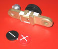
Battery Disconnect side post with + & - caps under view743 viewsThe upper and lower pieces of metal are clamped together but electrically seperate from each other. The connection between the two pieces is via the threaded part attached to the knob. When the knob is turned tight, current will flow between the two sections of metal.
|
|
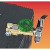
Battery Disconnect Wirthco 20308 Knob Top Post 890 viewsThis is a battery post style disconnect, usually for the negative terminal. There is a hole drilled in the round end off the battery so that flat terminal can be attached as well as the normal battery post terminal. I did not use this hookup arrangement, however I show it for information only.
|
|
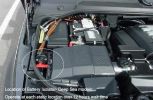
627 views
|
|

battery mounting and cables50 views
|
|

Battery Primer120 views
|
|

Caterpillar Battery Size cross reference chart and battery profiles including post layout753 viewsThis pdf has a dimension, (metric and inches), cross reference chart plus another sheet that provides BCI and DIN cross reference numbers and shows post locations plus bottom ridge tie down locations, (or the lack of).
This data was for me, hard to find, and helps one in selecting a suitable physical size of Aux battery for the space available.
|
|

Thread upload5 viewsImage uploaded in new thread
|
|
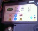
145 views
|
|

348 views
|
|

Battery TDV625 views
|
|

Battery test10 views
|
|

Thread upload3 viewsImage uploaded in thread 200678
|
|

Thread upload2 viewsImage uploaded in thread 194599
|
|

Thread upload2 viewsImage uploaded in thread 40682
|
|

Thread upload2 viewsImage uploaded in thread 204124
|
|

Thread upload13 viewsImage uploaded in new thread
|
|
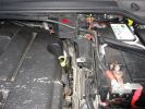
2nd Battery Pic 1362 views
|
|
Thread upload13 viewsImage uploaded in thread 136410
|
|
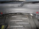
2nd Battery Pic 2318 views
|
|
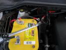
2nd Battery Pic 3378 views
|
|
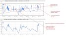
154 viewsRunning a 72L fridge on 100W solar with some driving. Conditions, overcast with some occasional sun. Overnight on Battery power. https://www.facebook.com/snomasterusa
|
|

Thread upload17 viewsImage uploaded in thread 172879
|
|

Thread upload19 viewsImage uploaded in thread 126959
|
|

Thread upload8 viewsImage uploaded in thread 152796
|
|
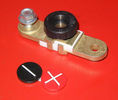
Battery Disconnect side post with + & - caps, top view617 viewsThis disconnect is designed for side post batteries. It can be used on either the + or - terminals. It can also be installed at the "other" end of the battery cable as well. In my install of the Aux battery, I installed this on the negative ground cable where the cable attaches to the body sheet metal. I have never used it but it seemed like a good idea at the time. The main battery hookup is pure stock.
For the hot side of the Aux battery, an Anderson PowerPole was used inline for the cable between the Aux and connecting to the spare bolt hole at the + post of the Main battery cable.
|
|

16 views
|
|

Thread upload5 viewsImage uploaded in thread 202239
|
|

Thread upload4 viewsImage uploaded in thread 180189
|
|

Positive battery terminal lead16 views
|
|

Thread upload28 viewsImage uploaded in new thread
|
|

Thread upload15 viewsImage uploaded in new thread
|
|

Thread upload28 viewsImage uploaded in thread 103032
|
|

Thread upload15 viewsImage uploaded in thread 135852
|
|

Thread upload14 viewsImage uploaded in new thread
|
|

Battery Voltage Chart35 views
|
|

Battery Voltage SoC67 views
|
|
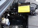
T-Max Adventurer 160lt/min Compressor too big for spare battery slot73 views
|
|

Battery 17 views
|
|

Thread upload3 viewsImage uploaded in thread 193933
|
|

Changing D4 Key battery30 views
|
|

Mvubu in Botswana 2014119 viewsMvubu 2014 Discovery 4 TDV6 XS, Corris Grey.Snorkel, OL Bull Bar, Winch,OME Heavy Duty Coil Springs,Light Guards,17" Black Wheels,Cooper ST max,Dual Battery+Inverter,Drawer Storage,FR Rear Ladder,Hannibal Roof Rack,80L Excel Long Range Fuel Tank,HiLift Jack Points,75L Water Tank.
|
|
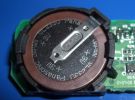
148 viewsKey Fob Battery
|
|
Auxiliary power sockets - TracTronics, Australia383 viewsA complete kit including two outlets, wiring etc connected to auxiliary Optima Blue top battery using their very effective SC40 split charge relay. One outlet between rear and front seats, and 2nd alongside loadspace 12v outlet, enables fridge to run when engine is not running, without affecting start capacity or vehicle functions.
|
|
TracTronics loadspace power socket 382 viewsThe 2nd power socket fitted alongside the original in the loadspace runs off the auxiliary Optima Bluetop battery to run a fridge when engine is not running. No more starting worries!
|
|
110 viewsTFC compressor in auxillary battery box
|
|

Thread upload3 viewsImage uploaded in new thread
|
|
CounterAct Power Supply mounted 247 viewsPicture is blurred, however power supply is 3M two sided tape to the flat black plastic of the second battery compartment just under the antilock brake pipes to the fender side of the brake fluid reservoir. The white wire to the left rear coupler pad runs thru the firewall hole near the steering column. The blue wire to the right front coupler runs across and above the engine following the other wiring looms that cross the vehicle.
|
|

B1C6258 viewsBATTERY SAVER OUTPUT CIRCUIT
|
|
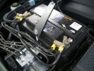
2nd battery in engine bay. Look under the rigid brake lines to see the solenoid438 views
|
|
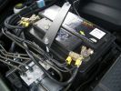
278 views
|
|
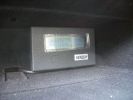
Genesis digital battery system - monitor in top glovebox325 views
|
|
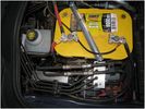
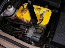
Optima Yellow top Battery in a D4266 views
|
|
Thread upload3 viewsImage uploaded in thread 200510
|
|

Thread upload4 viewsImage uploaded in thread 200510
|
|

Thread upload2 viewsImage uploaded in thread 200510
|
|

Thread upload1 viewsImage uploaded in thread 200510
|
|

Thread upload3 viewsImage uploaded in thread 200510
|
|
100A fuse mounted in secondary battery compartment15 views
|
|
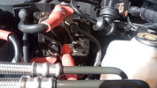
+12V supply141 views+12V taken from the regulator used to power the start/stop battery from MY14 onwards
|
|
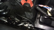
Cable routed from secondary battery box to front grille115 views
|
|
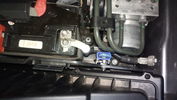
Fuse mounted in secondary battery box111 views
|
|
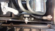
Fuse mounted in secondary battery box95 views
|
|

Deka Battery Dimension Data615 viewsThe battery size that I installed for my auxiliary was a BCI 40R battery as it was for me the easiest to fit and was also a cranking battery. The case profile was such that no tie down fins were located on either bottom end, (sides yes), and length wise, it was only about 11" (290 mm) long. As such, I did not have to grind the nibs at the front bottom of the plastic surround.
I did however raise the bottom of the battery above the angled nibs as I set the battery on a 1" (25mm) high plastic spacer. The total height, (battery plus spacer), was about 8" (200mm) so the battery top still fit under the Land Rover factory cover.
For the Aux battery, when I replaced the 40R, I installed an Interstate BCI 47 which is similar in size to a DIN H5. I was therefore able to eliminate the vertical spacer as the Group 47/H5 is the same height as the DIN H7/H8 stock LR spec starting battery. As such, the standard battery tie down bolts can be used without modification. The Group 47 battery is 9 11/16" long x 6 7/8" wide x 7 1/2" (190mm) high.
|
|
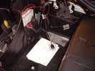
78 views
|
|
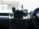
371 viewsHome made console, GPS in clip off mount, 29Mg radio,dual battery moniter,long rang tank gauge & elecric switches.A clip out removable console with no screws.PS also a camera mount.
|
|

Thread upload9 viewsImage uploaded in new thread
|
|
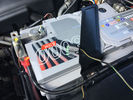
Thread upload9 viewsImage uploaded in new thread
|
|
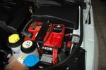
Aux Battery29 views
|
|
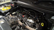
Dual Battery and ECU Chip175 viewsDual Barrery System by Traxide and Optima Yellow Top battey, Plus ECU Chip being fitted
|
|
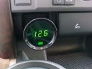
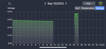
Battery voltage145 views
|
|
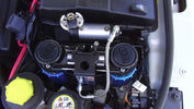
ARB CKMTA Twin Compressor180 viewsTwin Compressor with Manifold and Airtank. Tight fit but it fits. Also the ECU Chip is at the back and below up against the battery case.
I changed the hose quick release to a standard Air Hose Fitting eg like a workshop would use. My other truck has those also.
|
|
Take power direct from battery, routed cable through some rubber pipe, then taped up169 views
|
|
73 viewsAux battery tray - I found out you can remove the side as well as the top cover of the compartment.
|
|
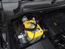
Optima Yellow Top16 viewsAGM auxiliary battery in second battery compartment
|
|
Ctek Smartpass11 viewsSmartpass used as second battery management system and isolator
|
|
Battery Voltage57 views
|
|
aux battery 120amp relay213 views
|
|
Main battery and accessory fuse box216 views
|
|

IBS contoller showing battery condition (engine off)218 views
|
|
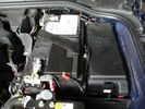
D4 Battery30 views
|
|
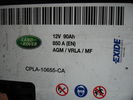
D4 Battery Specifications36 views
|
|

My old Landcruiser183 viewsApart from a battery and an exhaust I spent nothing on it.
|
|
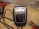
Ctek Battery Tester19 views
|
|
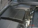
Main Battery Cover170 views
|
|
OptimaYellow Top Deep Cycle and Battery Tray194 views
|
|
OptimaYellow Top Deep Cycle and Battery Tray171 views
|
|
Aux Battery Cover167 views
|
|
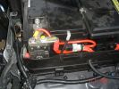
Aux to Main Battery201 views
|
|
Revived old battery (complements of the XS3600) comes in handy for power-testing65 views
|
|
battery charging66 views
|
|
Front-right view (looking forward) of partially installed winch and mount124 viewsThe closest bracket, with three rubber grommets, is the air bag sensor. Before beginning any of this work, be sure to disconnect battery and discharge any remaining electrical power. I didn't want to accidently drop this assembly and cause the airbags to deploy.
|
|

Additional 12V power, battery monitoring and USB sockets104 views
|
|

240V / 12V Power Board and Battery Charger102 views
|
|
added battery connector for charging direct from vehicle - the solar panel also plugs in here, so can be used for vehicle or trailer charging108 views
|
|
Dual Battery632 viewsOptima Battery and Surepower 1314
|
|
264 viewslook for the light shining through ...thats were the gromet is
|
|
261 viewslook for the light shining through ...thats were the gromet is
|
|
254 views
|
|
234 views
|
|
241 views
|
|
224 views
|
|
241 views
|
|
225 views
|
|
20 views
|
|
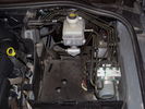
Spare Battery Bay with unknown box near the dipstick38 views
|
|

Thread upload11 viewsImage uploaded in thread 124456
|
|

The new Aux Battery charger for the D3 !196 views
|
|

D4 battery tray installed35 views
|
|

Car battery monitor19 views
|
|
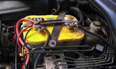
The auxiliary battery21 viewsThe auxiliary battery in the bay.
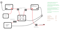
As the wiring diagram I made shows, there's a wire leading to the fuse box in the rear. (is going through the key-switch)
The second one is going to the fog lights. The smaller cables which should be connected to the head-lights, are connected to the battery.
The third one is going to the compressor (via a switch) (sits before the key-switch)
A fourth one is going to the CB and battery check display (sits before the key-switch)
|
|

Close up - Solenoid16 viewsA close up of the solenoid which is installed close to the auxiliary battery bay.
|
|

Close up - key removed18 viewsIn the center is the added switch with removable key.
Here the key is removed.
This is to add an additional 'protection' from discharging the auxiliary battery in case other people are working on the car and accidentally switches on any electrical bit :)
|
|
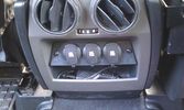
12V outlets for the 2nd row13 viewsI used a part of the old front (which was broke) to cut out a 'mount' for three 12V outlets for the second row.
The outer outlets are switched on whenever the ignition is on as I used the connector that originally was out there.
The middle outlet is connected to the auxiliary battery and is switched on/off through a rocker switch in the central console. (other picture)
This middle one is going to be used for our small fridge that usually resides just there when we're on holiday.
|
|
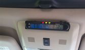
Battery check display15 viewsI mounted a digital battery display in order to see the voltage on the auxiliary battery.
There's also a thermometer which gives the inner and outer (via a side switch) values.
The display is switched on/off via another rocker switch.
|
|
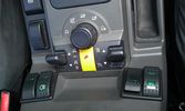
The on/off switch for the battery display22 viewsThe right inner switch 'powers' the auxiliary battery display. I might use that one to power on/off the driving camera (which will be arriving soon) as well. Although I'm not sure yet.
|
|
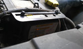
Solenoid engaged15 viewsAfter the engine's running for 5 minutes, the solenoid gets engaged and starts charging the auxiliary battery.
|
|
Harness chafing19 viewsWire insulation worn through with short to battery
|
|
Harness location15 viewsArea of harness that chafes against battery terminal
|
|
33Ah leisure battery in ABS case with Fused 12v socket48 views
|
|

2012 Mazda MX-5 Battery Test17 views
|
|
Aux battery fuse box18 viewsMy install of a fuse box.
|
|

Aux battery fuse box19 viewsClose up of fuse box
|
|

Battery voltages25 views
|
|
Battery box34 views
|
|
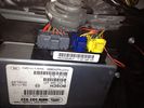
ECU pics behind battery 234 views
|
|

D4 Battery CCF AGM 120 views
|
|
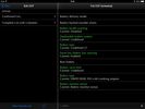
D4 Battery AGM 223 views
|
|
new Autron 12V Dual battery guage114 views
|
|
940 viewsFitting Second Battery and split Charge System
|
|
Aux Battery1054 viewsShows the aux 65Ah battery in place, top left of the picture is the 100amp circuit breaker feeding items sutch as , inverter, sub bass amplifiers, computer.
|
|

Aux Battery918 viewsShopwing the addition of the 35mm2 cable going to the split charge relay
|
|
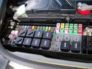
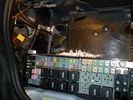
Picture of the engine compartment fuse panel5780 viewsEngine compartment fuse panel located near the battery. This is where F3E, (5 amp), F26E, (20 amp), Fuseable link 10E, (60 amp) and Relay 7E, the now upgraded 70 amp air compressor motor relay, part number YWB500220, (E is for Engine compartment fuse box), are all located. Fuse F35P, (5 amp), is inside the Passenger compartment behind the lower glove box door.
To keep the suspension from going down to the stops when driving, (or parked), it appears that it is only really necessary to remove F26E to depower the exhaust valve and generally keep all the valve block solenoid valves in a closed position trapping whatever air is within the air springs. F3E gets its power thru F26E, so when F26E is removed, the F3E circuit is automatically de-powered. F35P is more interesting in that battery power goes thru the ignition switch and F35P and then into the air suspension control unit. Apparently however, if F26E is removed, removing the F35P is not needed even when the engine is running.
With all fuses still in, if you have a problem, in practice, ideally, the compressor still works and will raise the 3 to an appropriate height. If so, one can then shut the engine off and allow the computers to go to sleep and then you remove the fuse(s). In actual practice, it seems that one need only pull the F26E fuse and can do so with the engine running. All the same, one might consider that the 3 is first a mobile computer, and secondly a 4x4. Computers prefer to go to sleep before the plug is pulled on them, however given that F26E circuit is always alive, then the computer never sleeps. With the fuse(s) pulled, and if you are still up, you can now be a 4x4 instead of a low rider. The whole purpose of the fuse pulling exercise is to depower the one and only system exhaust valve that is physically located within the compressor unit, (to keep it from opening), and secondarily to keep closed the four air spring solenoids within the block valves. This also shuts the air compressor down and stops the air compressor from making air even if the compressor is still good. That is why you initially need the fuse(s) in to allow the compressor to make air if it can.
|
|
Cable holder by battery195 views
|
|
75 viewsTouch Screen Battery
|
|
4GA Power Cable16 viewsFrom fuse box on aux battery - along channel.
|
|

PP002 12V135 views Brad Harris Socket
Hella Socket Cigarette
Lighter Socket
Battery Level Meter
External Terminals for Battery Charger or Solar Panel
ON/OFF isolator tie down strap excludes Battery
Built in fuses
https://www.facebook.com/snomasterusa
|
|
962 views'Rotronics' 3 stage battery management system installation
|
|
953 viewsAuxillary battery installation
|
|
796 viewsIn cab view of battery management monitors
|
|

MY2010 CCF Battery Section3 views
|
|

Second battery in Disco475 views
|
|

Second battery in Disco 477 views
|
|

New Exide AGM battery - Varta silver/calcium battery was replaced under warranty at 79680km.32 views
|
|

Partial remains of battery terminal bolt - Oops21 views
|
|

Towing socket battery charging cable39 views
|
|
aux battery bracket41 views
|
|
Battery Compartment Wire20 views
|
|

battery box multiplug7 views
|
|
96 views
|
|

Interstate Battery Dimension sheet641 viewsThis sheet is hard to find - the sheet is not on the Interstate corporate web site but some dealer web sites display it. The pdf shows most of their available batteries including the H7 and H8 sizes that are the LR North America replacement batteries for the main starting battery. These batteries are of the Land Rover desired "shallow" cycle high discharge current Maintenance Free, (Ca Ca), internal construction, (not AGM, but instead, Wet Flooded Lead Acid with battery "caps" and Ca grid separators).
For the AUX battery , the H6, (BCI Group 48), is probably similar in dimensions to the Varta E12V75N that is popular in Australia. For that battery to fit in the second battery compartment, you must grind out the angled nibs on the inside front bottom of the LR black plastic surround, something I did wish to do and hence installed a Group 40R on a spacer. Alternately, one can choose an Interstate BCI Group 47 which is similar to a DIN H5 for the AUX location. I did this when I had to replace my 40R. No vertical spacer is required and the stock battery tie down bolts and clamp work well.
|
|

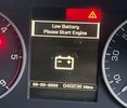
Cluster with dying battery62 views
|
|

Oxidation on neg battery poll48 views
|
|
16 views
|
|

JLR_Battery_Care_Manual_v232 views
|
|

Key Fob Repair Manual32 viewsHere is a way to diagnose problem and change key fob battery.
|
|

LA414-001 - Technical Bulletin - Battery Junction Box Connections99 views
|
|
Wiring harness for Hella 4000 Compacts260 viewsWired directly to the battery, all tucked away neatly now but can\'t find the picie
|
|
Thread upload7 viewsImage uploaded in new thread
|
|

Thread upload4 viewsImage uploaded in new thread
|
|

LR Electric Trailer Brake C2590 Female Connector606 viewsThis female connector, C2590, located up above and near the brake pedal is for the Trailer Electric Brake Controller hookup.
The Black wire in the bottom right is pin #3, the ground. The Blue wire to the left is pin #6, the Trailer Brake Controller output going to the rear trailer socket.
The White #4 wire is the 30 amp fusible link, (Link 6E in the engine compartment junction box), for the Brake Controller 12VDC power feed from the battery. Note that this would make a pretty good power source for CB radios and the like if no electric trailer brakes were required.
Pin #5 is a Green wire from the stop lamp switch, (the control input for the Brake Controller).
This plug is standard on all NAS (LR3) vehicles, but unlikely to be found on the D3 spec units.
|
|
Air Suspension ECU Fuse 35P cut off switch.3821 viewsThis shows the SPST rocker switch mounted in the blank plate installed in lieu of a manual passenger side air bag shut down switch - now automatic via passenger seat pressure switch. Fuse 35P (5 amps) is located in the interior fuse box behind the lower glove box and protects the ignition power supply to the Air Suspension ECU. When the SPST switch is moved to the OFF position, the RAISE /LOWER switch on the centre console is not powered, and hence does not function. As such, some signals from the wheel height sensors and CPU are ignored. By itself however, removing F35P will probably not stop the 3 from self dropping, particularly after the engine is turned off.
Fuse F3E, (5 amps), located in the engine bay fuse box by the starting battery protects the circuit that provides feedback to the Air System ECU indicating that the Compressor Relay has successfully operated and that the Air Compressor is or should be operational, can also be removed, (but is probably not totally necessary), as it gets its power thru F26E. Hence Fuse F26E, (20 amp), also located in the engine compartment fuse box is the fuse that must be removed. This fuse protects the circuit that provides full time battery power to the Air System ECU. When in place, current thru the fuse powers the periodic re-levelling action, (usually lowering a bit with that brief air release noise), that often occurs when the vehicle is parked and the engine is off.
Removing F26E fuse will stop the auto levelling action and also inhibit any other down to the stops signals, (engine running or not). When F26E is removed, no power can flow thru to F3E, hence removing F3E is more for insurance than an absolute requirement. The same with F35P, removing F26E removes primary full time power from the Air Suspension ECU, and hence removing the F35P fuse should not really be required either as long as F26E has been removed.
|
|

Battery Maintainer pigtail sticking out of Grill728 viewsThis is all you see when everything is put back together - just the pigtail and Weather Pack blanking plug. Most often, I have it all tucked back behind the grill.
In winter, there may be a second cord hanging out as well - the 120 VAC power cord for the engine block heater, a tea kettle like element inserted in the engine block. NAS petrol V8's do not have the Fuel Burning Heater, (FBH), installed, but instead in cold area markets have the block heater element assembly available as a dealer installed option. There is an argument to say that the heating element is factory installed in all cold climate V8 gasoline engines, however the appropriate power cord is not. If true, this means that all one needs to purchase is the area specific power cord and plugging in / attachment to the engine block located block heater.
As such, you will often see a conventional 120VAC three prong power plug hanging loose out of the grill of most vehicles here in the wintertime. In summer, most drivers tuck the plug back behind the grill as it is no beauty mark.
|
|
Battery Maintainer switch box and connector 723 viewsThe Hammond box contains a DPDT toggle switch with centre off. The Positive and Negative from each battery feeds to the switch. Depending on the setting of the toggle, (full left, full right,or centre off),the respective batteries connect into the pigtail that can stick out thru the grill when one wishes to connect the charger.
This allows one to charge each battery independently via a suitable battery maintainer. I use a CTEK unit that feeds a maximum of 3.3 amps at 14.4 or 14.7 VDC, depending upon setting. The wiring therefore allows for a slow recharge of either of the batteries separately if either one requires such.
|
|
Battery Maintainer switching box plug and CTEK Multi US 3300 charger. 706 viewsThe CTEK Multi US 3300 maintainer is just sitting there for the picture. In addition to topping up both batteries, the CTEK can provide power such that if the batteries were completely dead, there would be power to the door locks and hence, one could most likely still gain access via the remote once the starting battery charged up a bit.
The Land Rover recommended method is via the hidden key hole which is mechanical, however that presumes the mechanism is not frozen from lack of use. As such, the manual lock should be exercised at least once a year to ensure that it still functions.
The blanking plug sitting on top of the plastic box is of the GM Weather Pack series. That is what I like to use for vehicle wiring that is subject to moisture, (or not).
|
|
View from front left side looking towards rear aux battery compartment under cover 647 viewsAs there is no Fuel Burning Heater in the NAS V8 petrol vehicles, there is space available to install the FASKIT panel here. The piping is such that each air spring can be isolated from the air system and then filled one at a time manually via the Schrader valve. There are five Schrader valves and five shutoff valves. The fifth valve nearest the gauge controls air from the compressor, and can provide fill up air via a jumper fill line assuming the compressor is still operational.
|
|
Plastic cover and Box back on in Front of Radiator 638 viewsThe wiring loom is below the cover - nothing is crushed or distorted and all fits back together OK. The black plastic box with the DPDT, (centre OFF), toggle switch is to tie the battery maintainer to each of the two batteries per the Traxide Dual battery install. I can also get power to the power door locks if all fails.
|
|
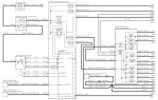
Power Window Circuit Sheet 1 from Battery to Central Junction Box (fuse box behind glove box)353 views
|
|

Underhood Fuse and Relay Box drawing 3055 viewsShows the various fuse and relay locations. Fuse 3E, (5 amp), and Fuse 26E, (20 amp), as well as upgraded 70 amp Relay 7, part number YWB500220, locations are displayed. Relay 7 sends battery power to the compressor from the 60 amp fusible link called up as 10E. Fuse 26E is what provides full time always on battery power to the air suspension ECU and hence powers the auto level wakeup when the vehicle is shut down and say parked for the night. Removing F26E is the primary method to disable the air suspension system; Removing F35P is more if you want to experiment with it from inside.
I found it useful when I had a suspension problem, (actually a wheel alignment problem picked up by the steering wheel angle sensor), that only showed itself on the highway but allowed for no trouble light driving in the city. This was because in the city, the steering wheel was always in motion and rarely was the vehicle driven in a near straight line for very much distance.
|
|

relocation of stuff to allow gigantic battery installation. The hood/bonnet barely closes wihout trouble.383 views
|
|

we put the fuses in the rear panel as well as the air tank gauge, air switch, and battery switch.417 views
|
|
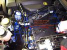
2nd battery fitting477 views
|
|
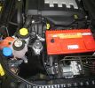
odyssey 2150 going in place467 views
|
|
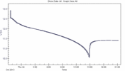
34 viewsLand Rover branded D3 battery of unknown age, discharged at 4.5A (= 90Ah at 20hr rate)
|
|

Horn Wiring Circuit LR3578 viewsThe is the wiring diagram for the dual horn circuit.
The Horn Relay, (R133), is not a big black thing hidden somewhere but instead what is called a FET, (and it is hidden)!
This is a Field Effect Transistor that is built into the circuit board that is mounted to the back of the fuse box that is located behind the lower glove box door on the passenger side of the 3. The related 15 amp fuse, 12P, is mounted in this fuse box and is often called F12P, where F is for fuse, and P is for Passenger compartment.
This is to help differentiate from another fuse and relay box, (the usual kind), that is located beside the starting battery in the Engine compartment. FxxE is often used in the naming of those fuses.
|
|
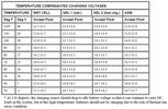
LR_Battery_temp_comp56 views
|
|

LTB00199 - Technical Bulletin - Battery Vent Tube Blockage - New Design Repair Procedure63 views
|
|
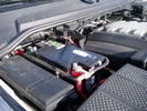
Main starting battery showing 1/2" hole drilled for power cable egress910 viewsView of OEM battery in Left Hand Drive LR3. This is supposed to be a Battery Group BCI 49 or H8 sized battery but in reality is the slightly shorter BCI 94R or H7 battery that fits easier lengthwise, (12 3/8" vs 14").
Note the 10mm hole drilled in plastic of surround to allow for entry of main power cable that runs between batteries. The cable bolts to a spare 6mm threaded hole in the OEM battery cable end; the light gauge wire runs to the front of vehicle to a connector for the CTEK MULTI US 3300 charger. Coloured felts, (red and green), are a material treated to reduce battery post corrosion. The OEM battery ground cable is only about a foot long and runs to an 8mm stud located on the inner fender just to the rear of the fuse case.
|
|
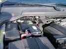
Main Battery showing aux cable feed running off positive battery post.776 viewsThe black wiring loom around the battery cable to the aux battery was a part provided with the Traxide kit. My goal was to run the cable low enough such that the battery box cover would go back on as previous.
Note the hole drilled in the side of the battery box such that the new cable could thread thru to allow the battery box top to still fit the same as prior to the addition of the cable to the auxiliary battery.
|
|
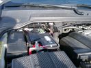
Thread upload54 viewsImage uploaded in thread 52879
|
|
Thread upload5 viewsImage uploaded in thread 144076
|
|
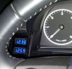
Battery meters26 viewsBattery meters - top for Main and bottom for Optima Yellow-top
|
|

Battery compartment plug155 views
|
|

NAS 7 plus 4 pin LR3 Trailer wiring, battery end. 549 viewsThis is the LR wiring diagram from the engine compartment battery location to the Electric Brake Controller connector, C2590, located under the dash near the brake pedal.
|
|
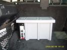
G4 battery box68 views
|
|
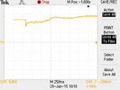
Cranking voltage new battery18 viewsMore details in .csv file
|
|

Cranking voltage new battery20 viewsDetailed measurement numbers of the new.jpg file.
|
|
Thread upload21 viewsImage uploaded in thread 205816
|
|
Thread upload0 viewsImage uploaded in thread 204138
|
|
Thread upload1 viewsImage uploaded in thread 204138
|
|
Thread upload0 viewsImage uploaded in thread 204138
|
|
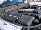
Overview of engine compartment from Main Battery side, (Passenger, LHD), looking across to Aux Battery753 viewsNote labels on main battery cover. The one you cannot read says that an auxiliary battery is installed on the other side. This is to warn service people should they wish to shut off all battery power.
The main starting battery is supposed to be of CaCa separator construction and DIN H8 or BCI Group 49 size. This means Calcium separators Wet Flooded Lead Acid, 13.9" long, 7.5" high and 6.9" wide.
On the Aux battery cover is a label saying to disconnect the blue Anderson single pole connector located under the cover by the brake reservoir. BCI Group 40R battery is small enough that the cover goes back on.
|
|
317 viewsStorage of recovery kit in 2nd battery compartment
1 x 8m strop, 1 x 2m tree strop, 2 x bow shackles & 1 x pully block
|
|
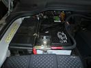
Traxide711 viewsLeft hand drive, primary battery with Traxide cable routed. The battery is on the right.
|
|
traxide cable run742 viewsTraxide cable between primary and secondary battery.
|
|
traxide808 viewsThis would be an ideal location for the traxide 80 kit, there are pre threaded holes available here.. would take a bit of fitting, and extending the cable to the primary battery would need to be extended.
|
|
rear socket install1412 viewsTraxide rear socket installation, alternative location. These holes must be precisely in this location because there is little clearance to the right of left due to the blower motor and hoses, etc.
|
|
rear socket install838 viewsThis photo shows the rear sockets installed, shows how the sockets in use are tucked up nicely and out of the way.
|
|
rear socket installation complete643 viewsThis demonstrates the rear sockets installed, shows how the sockets in use are tucked up nicely and out of the way.
|
|
rear socket installation complete680 viewsdemonstrate a neat and roomy install
|
|
DIII LR3 1442 viewsFitted Accessories
Devon 44 hidden winch
Warn XD9000 with remote kit
Safari Snorkel
Rover Specialties Rock Sliders with side nerf bars.
Yellow Top 2nd Battery
Available from --
http://www.lucky8llc.com/Products.aspx?ProductID=7136
Traxide SC80-LR D3 Kit B -TPSE
Available from --
http://www.traxide.com.au/Traxide.html
|
|
Battery Box Primary186 viewsThis visual is what is next to, behind and under your battery. It is important to note that the negative terminal which is prone to corrosion is in the rear, nearest to everything to maximize damage. The white powder pictured is baking soda. This is carefully used with a damp rag to neutralize any effect of battery acid (hydrochloric acid).
|
|
Negative Battery Cable208 viewsThis shows the corrosion from the negative terminal on the Negative to body ground. This is likely due to gas released through the negative post. It appears to be a common problem with the LR3. As a result of this corrosion left unchecked will damage the computer ecu and cables mounted near and below the battery.
|
|
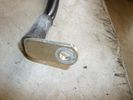
Negative Battery Cable159 viewsClose up of the corrosion damage to negative cable.
|
|
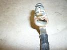
Negative Battery Cable164 viewsClose up of the corrosion damage to negative cable.
|
|
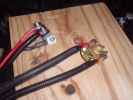
New battery terminals69 views
|
|
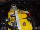
Re-wiring of 2nd aux battery130 views
|
|
Wiring from spare battery71 views
|
|
12 Volt supply from aux battery82 views
|
|
12 Volt supply from aux battery86 views
|
|

Both connectors wired to aux battery90 views
|
|
Dual battery16 views
|
|
Dual battery21 views
|
|
Dual battery19 views
|
|
Battery comfort lead16 views
|
|
Offroad van duel battery connection75 views
|
|
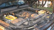
Triple battery connection - battery location104 views
|
|
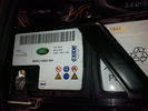
Thread upload3 viewsImage uploaded in thread 179157
|
|
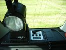
424 viewsThe second battery has its own voltmeter
|
|
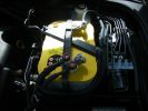
396 viewsThe OPTIMA aux battery
|
|
343 viewsSurePower 1315-200 battery isolator
|
|
352 viewsThis is how the battery isolator is connected with the main battery.
|
|
114 views
|
|
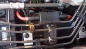
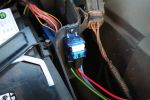
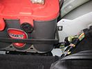
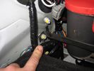
153 viewsI routed the white signal wire from the junction box which I positioned at the side of the battery, back and under the bonnet seal.
|
|
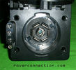
NAS 7 pin + NAS 4 pin Flat Trailer Socket308 viewsThis is the vehicle end of the NAS trailer harness that is located behind the removable plate centered within the rear bumper by the towing loop. Re the four pin flat connector, from the bottom, the exposed bare lower pin is the ground, usually the White wire on a NAS trailer. The next pin up is normally a Brown wire on a trailer and is for the Tail Lights. The third pin, normally a Yellow wire, is the left signal light; the top pin, normally a Green coloured wire, is the right signal light.
Re the round connector, from the notch in the plastic surround, clockwise, the first blade is ignition controlled +12VDC battery power, (only alive when engine running), and on the Land Rover factory harness is an Orange wire; on a NAS trailer, usually Red but perhaps a Black wire.
Next blade clockwise at 3:00 o'clock above, is the Right Turn signal light, a Green wire on the LR harness, and also on a NAS trailer.
At 5:00 o'clock, the next blade is for the Electric Brakes and is Blue on both the LR harness and on a NAS trailer.
The Ground wire is next, White on both the LR harness and on a trailer.
At 9:00 o'clock above, is the Left Turn signal, Yellow on both the LR harness and on a trailer.
The last blade to the left of the line up notch is the Tail Light circuit. On the LR harness, the wire colour is Brown with two White stripes and on a NAS trailer, Brown.
The centre pin is for the Reverse Back Up lights and is Black on the LR harness and often Purple on NAS trailer wiring but can be Black also.
Note that when the socket assembly is installed on the 3, the notch in the plastic surround is on the left - that is rotated 90 degrees anticlockwise to the picture above. In other words, When installed on the 3, the 4 pin flat connector lays horizontal and is located below the round socket.
|
|

Thread upload10 viewsImage uploaded in thread 153940
|
|
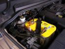
Aux Battery Installed1032 viewsIts a tight fit, but uses the LR battery mounts and bracket, slightly modified.
|
|
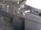
2 new rear 12v outlets933 viewsI added these two after market 12v oulets that are directly wired via a 30amp fuse to the aux battery. Why 2? Well you can never have enuff in my experieince... There\'s also a 12v socket wired to the ignition on the other side.
|
|
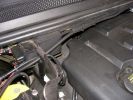
Main Feed799 viewsHere\'s the shielded positive feed from the main battery. Runs accross the fireall with lockties to support.
|
|
Optima Battery782 viewsBattery makers sheet for all you rivet counters out there.
|
|
Installed and wired863 viewsShows the wiring loom to the isolator, the feeds (fused link) to the rear outlets and the other feeds are for the battery meter
|
|

Optima Battery91 views
|
|
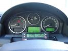
ScanGauge II on steering column of LR3800 viewsMAP is Manifold Absolute Pressure, what I call Vacuum.
The volts is I think the battery charging voltage as it moves around from about 12.4 when shut down to 13.5 when the batteries seems charged; 14.9 is about as high as I have seen it display.
You also have RPM, speed in MPH or KPH, coolant temperature and a bunch of other readings including sort of instantaneous fuel in a variety of units.
Also under some conditions, the ScanGauge will reset the MIL light as well. The background colour of the display can be changed to many different colours. I have it set to match the LR green.
|
|

Thread upload1 viewsImage uploaded in thread 200210
|
|

Thread upload2 viewsImage uploaded in thread 200210
|
|
Thread upload4 viewsImage uploaded in thread 200210
|
|
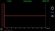
Thread upload13 viewsImage uploaded in thread 184914
|
|
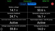
Thread upload14 viewsImage uploaded in thread 184914
|
|
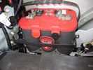
291 views
|
|
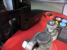
253 views
|
|
241 views
|
|
270 views
|
|
10 views
|
|

Thread upload26 viewsImage uploaded in thread 161552
|
|
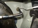
120 viewsThe signal wire then drops into the aux battery box and through the bulkhead grommet
|
|
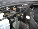
Signal wire through aux battery box to grommett124 views
|
|

Thread upload16 viewsImage uploaded in thread 162511
|
|

Thread upload3 viewsImage uploaded in thread 191860
|
|
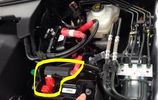
Thread upload11 viewsImage uploaded in thread 177417
|
|

Tekonsha Ford Brake Controller Adapter part number 3035-P275 viewsThis is the adapter cable between the Brake Controller and the existing C2590 female plug located near the brake pedal on NAS spec LR3's. The flat 4 pin plug of the adapter cable connects to the Controller; the rectangular 6 hole male plug to C2590.
There are only four conductors in the adapter cable, but one will see five pins within the Land Rover C2590 plug. The #2 pin is not required for the NAS setup. #2 pin is the circuit between the head lamp switch and vehicle side running lamps required in the civilized world.
The single pin at the bottom in the picture is #3 and on the Land Rover, a Black wire tied to ground. The other pin at the bottom and across to the left is #6, and Blue on the Land Rover. This is the Brake Controller output to the trailer socket at the rear.
#4 is the pin at the top left, and is a White coloured wire from the battery. Pin #5 is from the stop light switch, and is Green on the Land Rover.
Note that the adapter cable colours do not necessarily follow all the above referenced Land Rover colours.
|
|
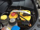
Traxide - 2nd battery19 views
|
|

Varta Battery Dimension chart570 viewsThis pdf provides Varta dimensions for among others, the E12V75N, (old DIN H6 or 85605 or BCI Group 48 size). This appears to be a deep cycle battery and the choice for many re the Aux battery install as long as you are willing to grind away the angled nibs at the bottom front of the battery surround. My choice was a shallow cycle battery intended for cold weather related engine starting rather than winch use.
Note the pdf Varta batteries are all deep cycle batteries suitable for running fridges, winches etc, rather than for engine starting and hence a good Aux battery if those are the intended uses rather than engine starting.
Varta now makes a Varta G14 with AGM technology and known as a Stop Start Plus battery. It is 95Ah, CCA of 850A; length 353mm; Width 175mm; Height 790mm and is specific for these newer stop start vehicles such as some D4's. For the 3's, one is still probably better off with an H8 sized battery but of the older Wet Flooded Lead Acid type and battery caps rather than a sealed AGM.
The Land Rover part number for the recommended battery is LR033179.
|
|
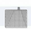
Varta battery grid65 views
|
|
![Filename=vl2330-rechargable-panasonic-li-ion-battery-1067686-p[ekm]170x170[ekm].jpg
Filesize=3KB
Dimensions=170x170
Date added=16.Jun 2017 vl2330-rechargable-panasonic-li-ion-battery-1067686-p[ekm]170x170[ekm].jpg](albums/userpics/33392/thumb_vl2330-rechargable-panasonic-li-ion-battery-1067686-p%5Bekm%5D170x170%5Bekm%5D.jpg)
Thread upload10 viewsImage uploaded in thread 161047
|
|
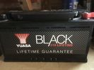
Thread upload9 viewsImage uploaded in new thread
|
|
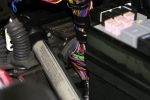
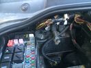
Main loom passes through bulkhead behind the engine bay fuse box next to the battery140 views
|
|

space where second battery could live155 views
|
|
|
|
|
|