| Search results - "amplifier" |

1 TMC Amplifier51 views
|
|
TV ariel x2 with built in power amplifier.82 views
|
|

Logic7 Amplifier31 views
|
|

Alternator and Regulator Wiring Diagrams, TDV6 and petrol V8 and V61989 viewsThis is a three page pdf that shows the alternator and regulator wiring for the petrol V6, petrol V8 and TDV6. The pdf can be either printed or by right clicking on the displayed pdf, rotated as required for viewing.
Of interest is that the regulator gets its instructions primarily from the Engine Control Module (ECM) and only secondarily from the vehicles electrical buss. The conductor from the battery thru the 5 amp fuse F20E is to provide initial power to excite the alternator at startup and then secondarily, to instruct it if the PWM signals were not available. Primary instructions to and from the ECM are thru the two other conductors via a digital like Pulse Width Modulated (PWM) signal.
If F20E, the 5 amp engine compartment fuse box fuse is blown, the red alternator light on the dash will be illuminated. This means that the alternator could be OK, but if the F20E fuse is blown, no electricity will be generated. Hence check the F20E fuse if you get a red ALT light or some indication of the alternator not working.
Regarding operation of the red ALT light on the dash, it is not the regulator within the alternator that tells the red light to illuminate, or not, but instead the ECM. This is the reason the red light does not function in the same manner as with older vehicles. With the 3, sometimes you have illumination and sometimes not depending upon what the ECM is thinking. What this means is that you can have an alternator that is failing but the red light does not illuminate as the ECM is compensating for reduced alternator output - maybe by draining the battery and or cutting back on vehicle electrical loads such as shutting off or cycling the radio amplifier or heated seats.
|
|

Entertainment System Wiring Diagrams2331 viewsThe 12 page pdf has the wiring diagrams for the low and high line "radio" and various components such as the amplifier, phone modules,NAV display, antennas and satellite radio and TV.
|
|
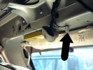
6 Radio diversity Amplifier59 views
|
|
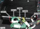
376 views
|
|

Amplifier wiring98 viewsChanges for converting High Line to Premium.
|
|
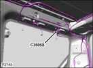
AM and FM Aerial amplifier97 views
|
|
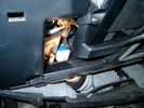
Brake Switch Visible thru Opening4973 viewsThe blue and white bit is the switch; the sort of gold appearing box,(it is really black), you will not see in your 3 as it is a Smooth Talker brand amplifier for my Blackberry phone antenna. This install is detailed in the SmoothTalker phone antenna section of my gallery.
One way to remove and install the switch is to lower the "horizontal" panel above the brake pedal as shown where the flashlight head is located. To actually remove the switch, you slide your hand thru the gap and rotate the switch clockwise 1/4 turn while watching thru the rectangular opening. Installation of the new switch is the reverse of above - 1/4 turn counterclockwise.
Before you remove the switch, note its orientation - horizontal with electrical wires to the left. That is the way it should look after replacement as well.
The second time I replaced the switch, I did it all thru the rectangular opening and did not remove the horizontal panel - that is experience helping out.
The knee kick you have to remove regardless. It is sort of hinged at the bottom so you just pull at the top and sort of rotate the knee panel and then pull upwards for two plastic "fingers" to clear the slots they reside in.
|
|
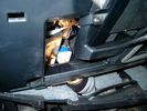
Smooth Talker Amplifier Box mounted below near steering column.179 viewsThe gold look box due to the lighting, (actually black), is the antenna amplifier located near the steering column. It can be put anyway but this seemed an OK location as I ran the antenna connector cable rearward from here to the back corner of the 3 and then up to the underside of the roof glass at the rear. The blue/white thing is the brake light switch that often must be replaced. See the Brake Light Switch file within this Gallery regarding the switch replacement.
|
|

419-08 Low and High line radio systems components and operation838 viewsThis 15 page pdf displays the radio components including pinouts for both the low and high line head units and the two Harman Kardon amplifiers including the Logic 7 amp. The steering wheel controls for both the radio and phone system are also outlined along with mention of the Sirius satellite radio feature.
|
|
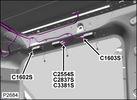
FM and DAB3 Aerial amplifiers118 views
|
|
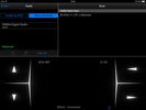
B1591 324 viewsB1A56-11
Antenna - Circuit short to ground
Diversity antenna amplifier circuit short to ground
Refer to the electrical guides and check the diversity antenna amplifier circuit and the antenna for short circuit to ground
|
|
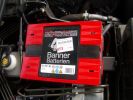
Aux Battery1054 viewsShows the aux 65Ah battery in place, top left of the picture is the 100amp circuit breaker feeding items sutch as , inverter, sub bass amplifiers, computer.
|
|
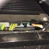
Harmon Kardon Audio Amplifier11 viewsLocated underneath right hand front seat. Connected to MOST system
|
|
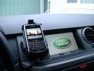
BlackBerry Tour 9630 mounted on air vent265 viewsThe antenna amplifier is mounted lower near the steering column. The amplifier box is painted black but looks sort of gold coloured due to the lighting in the other jpg showing the amp located under/near the steering column.
|
|

LTB00008 - Technical Bulletin - Audio System Amplifier Diagnostic Aid75 views
|
|
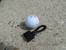
MOST fiber optic loop tool468 viewsThe looping tool in the jpg uses the Land Rover type plastic fiber optic cable with both ends feeding back into a female fiber optic connector that mates with the male fiber optic connectors on the Land Rover system.
The purpose of the loop is to allow one to disconnect MOST connected items such the BlueTooth module or the HK amplifier but allow the MOST system to still transmit signal from the head unit as the circuit would remain closed and hence complete. Of course with the Bluetooth module disconnected, there would be no Bluetooth available, however the radio and NAV would still function.
The looping tool allows one to troubleshoot the system by removing one component at at time from the MOST loop. In other words, what might appear to be a radio problem could be a Bluetooth problem - that sort of thing.
|
|
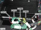
Thread upload1 viewsImage uploaded in thread 180578
|
|
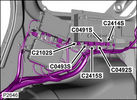
Audio amplifier & DAB unit & Door lock system106 views
|
|
|
|
|
|
|