| Search results - "Wiring" |

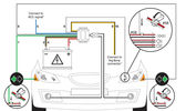
0000 LR Bluetooth dealer Kit install instructions1608 viewsThis 17 page pdf is mostly a series of pictures showing how to install the original Land Rover dealer installed Bluetooth kit for circa 2005 / 2006 three's. Also included are three wiring diagrams sheets related to the pairing code 0000 Bluetooth install.
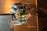
This pdf is useful if you are now removing the 0000 kit to install the optical 2121 MOST D4 module, an easier install than the 0000 kit ever was.
|
|
heated seat (base) wiring411 viewsThe Small connector takes the plug from the seat back pad, the larger connector (with red) is fitted into the multiplug casing uder the seat - the male side of this is already pre-wired.
|
|
heated seat wiring352 views
|
|
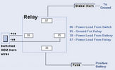
04horn37 views
|
|
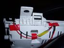
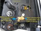
Insrument panel rear 34 viewsShowing wiring for heater and lights on indicator
|
|

Thread upload25 viewsImage uploaded in thread 176268
|
|
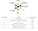
Thread upload6 viewsImage uploaded in thread 176361
|
|

Thread upload15 viewsImage uploaded in thread 153386
|
|
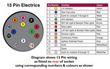
Thread upload13 viewsImage uploaded in thread 165627
|
|
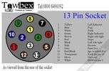
Thread upload16 viewsImage uploaded in thread 184914
|
|
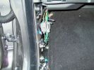
N/S Kickpanel wiring harness for AUX input4288 views
|
|

97 viewsOut at the C pillar. From here wires were threaded through the rear seatbelt anchor point into the commercial box, which is the hub of all the wiring and CarPC installation
|
|
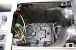
73 viewsStarting the switch wiring
|
|
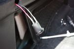
72 viewsWiring for 12V socket attached to socket
|
|
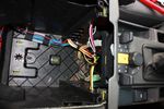
70 viewsAll switch wiring neatly routed to exit hole
|
|
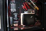
78 viewsElectrical items fitted in place and wiring in progress
|
|

Audio control wiring loom LEFT16 viewsLeft Door wiring loom for audio controls
|
|

B post door plug14 viewsRear door wiring harness plug to B post
|
|

Rear right door audio wiring loom15 viewsRight Loom
|
|
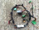
Front Console Wiring Loom AH32-14B079-BC Pic 39 views
|
|
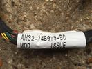
Front Console Wiring Loom AH32-14B079-BC Pic 27 views
|
|
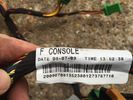
Front Console Wiring Loom AH32-14B079-BC6 views
|
|
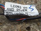
Wiring Loom F Console AH22-14B079-AC Pic36 views
|
|
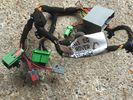
Wiring Loom F Console AH22-14B079-AC Pic211 views
|
|
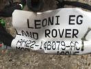
Wiring Loom F Console AH22-14B079-AC7 views
|
|
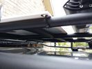
solar panel install356 viewsAt least at this point, I mounted it by using Clear Silicone RTV. This stuff is kind of like glue, but can be removed. If it doesn't hold up after curing and driving, I'll remove it and come up with another plan. I used heavy cable ties on the 4 grommets, in case it lets loose, it won't take out my wiring and the car behind me. 2 Panels are dandy like this, but I don't want to permanently block the roof space. Grape Solar to power my snomaster fridge
|
|
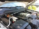
Traxide USI-160 Install515 viewsOverview picture of Traxide USI-160 upgrade install. This was an upgrade from the SC80 which performed flawlessly. The USI-160 had two relays and can deliver more amperage. As a result, the wiring was upgraded to 4/0 Welding Cable (warn) and heat shielding was added. The unit performs flawlessly to support 2 HAM Radios, Fridge, etc. Like me https://www.facebook.com/DifferentialPartsUS
|
|
Wiring342 viewsThis is the final wiring configuration. It shows the dual battery wiring, 75A wiring run to the boot, the winch and in the lower right you can see a few turns of coax with a snap on ferrite near the base of a VHF Antenna.
|
|

Alternator and Regulator Wiring Diagrams, TDV6 and petrol V8 and V61989 viewsThis is a three page pdf that shows the alternator and regulator wiring for the petrol V6, petrol V8 and TDV6. The pdf can be either printed or by right clicking on the displayed pdf, rotated as required for viewing.
Of interest is that the regulator gets its instructions primarily from the Engine Control Module (ECM) and only secondarily from the vehicles electrical buss. The conductor from the battery thru the 5 amp fuse F20E is to provide initial power to excite the alternator at startup and then secondarily, to instruct it if the PWM signals were not available. Primary instructions to and from the ECM are thru the two other conductors via a digital like Pulse Width Modulated (PWM) signal.
If F20E, the 5 amp engine compartment fuse box fuse is blown, the red alternator light on the dash will be illuminated. This means that the alternator could be OK, but if the F20E fuse is blown, no electricity will be generated. Hence check the F20E fuse if you get a red ALT light or some indication of the alternator not working.
Regarding operation of the red ALT light on the dash, it is not the regulator within the alternator that tells the red light to illuminate, or not, but instead the ECM. This is the reason the red light does not function in the same manner as with older vehicles. With the 3, sometimes you have illumination and sometimes not depending upon what the ECM is thinking. What this means is that you can have an alternator that is failing but the red light does not illuminate as the ECM is compensating for reduced alternator output - maybe by draining the battery and or cutting back on vehicle electrical loads such as shutting off or cycling the radio amplifier or heated seats.
|
|

Entertainment System Wiring Diagrams2331 viewsThe 12 page pdf has the wiring diagrams for the low and high line "radio" and various components such as the amplifier, phone modules,NAV display, antennas and satellite radio and TV.
|
|

Exterior Lighting (Fog Lamps - Non NAS)13 viewsWiring diagram for non-NAS fog lamps
|
|
04278 viewsThe green wiring harness is the speaker outputs. Green is + and Green with white stripe is -. We tested all the wires with a 9V battery to figure out which went to what speakers then clearly labeled them as we did.
|
|
Rear wiring213 views
|
|
06257 viewsWires from the wiring harness of the V1000 to hook up.
|
|
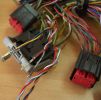
AirBag Pins79 viewsNew Wiring at AirBag ECU just need to back out the pins of the old and clip in the new.
|
|
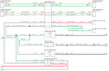
ABS Wiring48 views
|
|

Fin cell phone aerial drawing190 viewsThe factory aerial for the factory NAV / GPS on my 2005 HSE is within the high mounted stop light lens at the top of the upper hatch door. I do not have the factory installed phone kit, and as such, do not have the fin installed; instead there is just a plastic blanking insert to fill the cell phone aerial wiring hole in the metal portion of the roof; hence this requirement for an "external" cell antenna. For those that do have the fin on their glass roof, the fin is screwed on to a glued on plastic gasket, (sort of), and not bolted thru as per the metal roof 3's.
|
|

AFS Retrofit loom info77 viewsinformation about how to build a loom to retrofit AFS
|
|

Thread upload3 viewsImage uploaded in thread 193523
|
|

Alternator female plug looking down into top373 viewsThis shows the plug connected to the alternator wiring harness looking down into the top of the plug.
The cavity marked 1 is the AS or BATT SENSE and the wire colour most likely has Brown/Green on it.
The cavity marked 2 is the RC or ALT CON and the wire colour most likely has Red/White on it.
The cavity marked 3 is the L1 or ALT MON and the wire colour likely has Green/White on it.
I say "most likely" as the wire colours are not always the same on all vehicles.
Also the terminal 1 conductor destination is more likely C0570-175 rather than per the jpg.
The #3 pin is located closest to the big B+ terminal.
|
|
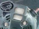
Alternator Plug and B+ terminal918 viewsPictured is the rear of the older Land Rover part # YLE500190 alternator showing the shiny cooling fin of the Regitar VRH2005-142 regulator under.
The first pin in the far left side of the connector is numbered #1 in the LR electrical wiring diagrams and is Battery Voltage Sensing (BVS); the middle pin, #2 receives a Pulse Width Modulated (PWM) signal from the Engine Control Module (ECM), and the right pin, #3 carries a PWM signal back to the ECM. Terminal Pin #2 on the LR wiring diagrams is called Alternator Control or ALT CON; Pin #3 per LR is called Alternator Monitoring or ALT MON.
Pin #1 is similar to what in older designs used to be called A or Batt, but is now called by Denso, S, AS, or Alternator Sensing for this design. Pin #1 also provides power to excite the alternator at startup until the PWM instructions over ride the battery voltage info. Land Rover calls the electronics under the pins a Smart Regulator, ironic, as it has to follow orders from the ECM rather than give the orders - new age thinking I guess. This is different from older design internal regulators that look at just the battery or the electrical buss voltage and then decides itself what to do.
It is almost like we are back to the external regulator designs of old, except that the ECM may decide that instead of telling the alternator to make more power, to load shed, and hence shut down the heated windscreen, seats, or whatever other electrical loads it decides are appropriate. My view is that the "smarts" are in the ECM and that the "regulator" should be regarded if not dumb, then as being a slave to the ECM.
|
|

Amplifier wiring98 viewsChanges for converting High Line to Premium.
|
|

ASC Wiring Diagram31 viewsASC Wiring Diagram
|
|
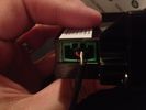
Aux Input Wiring Harness69 viewsUsed a modified PC CD interface cable to connect to stock female harness. Pins 3(R), 4(L), 5(G)
|
|
301 views
|
|
417 views
|
|
262 views
|
|
263 views
|
|

92 views
|
|

Thread upload13 viewsImage uploaded in thread 138228
|
|
9 views
|
|
9 views
|
|

44 views
|
|

35 views
|
|

34 views
|
|

40 views
|
|

28 views
|
|

30 views
|
|
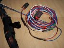
Burnt Bit97 viewsThis bit of wiring going to the connector was so close to bulkhead it got a bit burnt, Its for the clutch switch on a manual used for EPB, It will be replaced connector to pin with the wiring shown.
|
|

Thread upload10 viewsImage uploaded in thread 54001
|
|

Can Bus with splice locations2 views
|
|
Auxiliary power sockets - TracTronics, Australia382 viewsA complete kit including two outlets, wiring etc connected to auxiliary Optima Blue top battery using their very effective SC40 split charge relay. One outlet between rear and front seats, and 2nd alongside loadspace 12v outlet, enables fridge to run when engine is not running, without affecting start capacity or vehicle functions.
|
|

HVAC Climate Control Wiring Diagram 62 views
|
|

Thread upload39 viewsImage uploaded in new thread
|
|
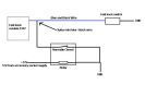
CounterAct Power Supply mounted 246 viewsPicture is blurred, however power supply is 3M two sided tape to the flat black plastic of the second battery compartment just under the antilock brake pipes to the fender side of the brake fluid reservoir. The white wire to the left rear coupler pad runs thru the firewall hole near the steering column. The blue wire to the right front coupler runs across and above the engine following the other wiring looms that cross the vehicle.
|
|
Thread upload20 viewsImage uploaded in thread 169498
|
|
Drivers seat wiring Cut151 viewsSpare connector from my second hand seats shows where wiring to seat gets cut presumably by emergency services.
|
|
Thread upload0 viewsImage uploaded in thread 201952
|
|
Thread upload1 viewsImage uploaded in thread 201952
|
|
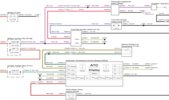
D3_FBH_Wiring24 views
|
|
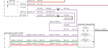
D3 Fuel Pump Wiring22 views
|
|
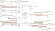
D3_Glow_Plug_Wiring_119 views
|
|
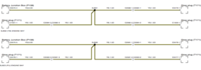
D3_Glow_Plug_Wiring_216 views
|
|
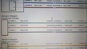
Thread upload18 viewsImage uploaded in thread 184914
|
|
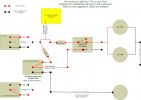
251 views
|
|
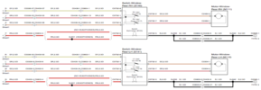
D3_Rear_Window_Wiring19 views
|
|
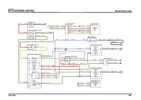
Thread upload22 viewsImage uploaded in thread 123695
|
|

Heated Seat Element Wiring - Seat Base48 views
|
|
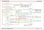
Thread upload19 viewsImage uploaded in thread 162372
|
|
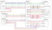
D3_TCCM_Wiring17 views
|
|

Thread upload10 viewsImage uploaded in thread 192004
|
|

Thread upload5 viewsImage uploaded in thread 206343
|
|

Thread upload2 viewsImage uploaded in thread 206743
|
|

Thread upload7 viewsImage uploaded in thread 206812
|
|

Thread upload3 viewsImage uploaded in thread 170152
|
|

Thread upload21 viewsImage uploaded in thread 142490
|
|

Thread upload18 viewsImage uploaded in thread 150396
|
|

216 views
|
|

45 views
|
|
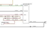
D4 Aux Lights Switch Wiring Diag80 views
|
|

D4_FBH_Wiring19 views
|
|

D4 Fuel Temp Wiring17 views
|
|
D4_Glow_Plug_Wiring16 views
|
|

Thread upload62 viewsImage uploaded in thread 120453
|
|

7 views
|
|

Hardware location of wiring audio information and entertainment system2214 viewsHardware location of wiring audio information and entertainment system2
|
|

D3 WIRING 08MY26 viewsImage uploaded in thread 185033
|
|

Thread upload8 viewsImage uploaded in thread 187892
|
|

Discovery 3 Exterior Light Wiring69 views
|
|

Thread upload9 viewsImage uploaded in thread 190934
|
|

Thread upload10 viewsImage uploaded in thread 193383
|
|

Thread upload12 viewsImage uploaded in thread 198096
|
|

Thread upload18 viewsImage uploaded in thread 147705
|
|
Thread upload28 viewsImage uploaded in thread 108293
|
|
Thread upload31 viewsImage uploaded in thread 108293
|
|
Thread upload12 viewsImage uploaded in thread 177861
|
|

Thread upload7 viewsImage uploaded in thread 206759
|
|

Thread upload5 viewsImage uploaded in thread 208122
|
|

Thread upload1 viewsImage uploaded in thread 209484
|
|

D4 Headlight Wiring Diagram 1 VIN 51332638 views
|
|

D4 Headlight Wiring Diagram 2 VIN 52454535 views
|
|
Lighting Wiring jpg58 views
|
|
Steering Switches JPG53 views
|
|

Steering Switches51 views
|
|
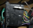
New Speaker Cables.111 viewsThis is the door connector, Main loom to Right, Door side to the left. to the top of the connectors you can see green and Green white wires which are the speaker ones. The door wiring is premium and has two pairs, the main loom was a 1 pair high line, so i am adding the pair you see (one already pinned up) to upgrade the loom to premium.
|
|
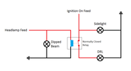
Thread upload22 viewsImage uploaded in thread 116751
|
|
Thread upload13 viewsImage uploaded in new thread
|
|
Some of the new wiring514 views
|
|
Picture of wire direct into headlight wiring181 views
|
|
Again just another pic of the wiring into the main175 views
|
|
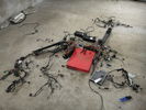
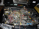
246 views2 wiring looms , looks like a mess but i know what i am doing ?
|
|
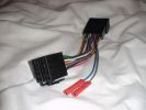
Wiring harness for Kenwood to Disco 360 views
|
|
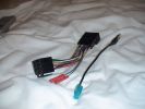
Aerial abd wiring adapter52 views
|
|

66 viewsI was quite proud of my wiring work - My Nursing Degree didn't cover too much content on auto electrics.
|
|
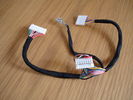
D3 Steering Wheel Wiring34 views
|
|
In readiness for soldering the remote wiring to the circuitboard61 views
|
|
DSC_003320 viewsCan Bus Wiring Engine Bay
|
|
Wiring in left hand rear wheel arch, behind plastic shroud.726 views
|
|
Left hand rear wheel arch, behind plastic shroud.720 viewsThis is the standard wiring.
|
|
The swinging lump of iron that sit under the back,871 viewsLook how close it is to the wiring!
|
|
DVD Power and Audio Connectors214 views
|
|
DVD Dome Light connector194 views
|
|

View of all 3 DVD connectors202 views
|
|
EAS Wiring23 views
|
|

Wiring Seats56 views
|
|
Thread upload4 viewsImage uploaded in thread 149835
|
|

Thread upload13 viewsImage uploaded in thread 118475
|
|

EPB wiring kit46 views
|
|

Thread upload1 viewsImage uploaded in thread 175087
|
|
101 views
|
|
86 views
|
|
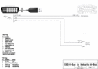
64 viewsOBD2 adapter to FBH wiring diagram, corrected and labelled for plug view.
|
|
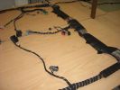
Finished seats area108 viewsThis is a shot of the loom when it was finished from the pass (RHD) door
Both of the seats wiring can be seen, i replaced the conduit on the bottom right and the Yaw rate sensr connector can also be seen in the middle.
|
|
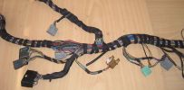
Finished Passenger Kick panel area131 viewsMissing connetor (left most grey) & wiring in, (plastic bracket was broke will use the one in the car) Airbag wires & connector to connector previously cut replaced (on top of grey one to right).
And you can even see the 2 new speaker wires going into the Pass door connector at the very bottom.
|
|

Pass seat wiring108 viewsClose up showing the re worked Pass seat wiring on the D3 loom next to the sport one.
|
|

flir wiring31 views
|
|

Wiring Diagram Fog Lamps76 viewsR130 is the (R5 relay under the hood) The wire is blue grey that is hot when the high beams are on and opens the relay contact that turns off power to the fog lamps. North America Only
|
|

Fogs & LEDs Wiring - Pic 183 views
|
|

Fogs & LEDs Wiring - Pic 265 views
|
|

Fogs & LEDs Wiring - Pic 363 views
|
|

Fogs & LEDs Wiring - Pic 458 views
|
|

Fogs & LEDs Wiring - Pic 557 views
|
|
171 views
|
|
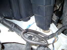
Front coupler pad to right front under air filter housing 158 viewsCoupler Pad is attached to the flat metal surface just behind the rectangular drain off of the air filter housing. The last 3 inches (75mm) of the 1/4" (5mm) black flex wiring loom was then threaded over the last bit of wiring. One of the other jpg's is less washed out and shows the coupler pad a bit better.
|
|
Front Coupler pad to right front under air filter housing 156 viewsThe brighter white "square" behind the black air cleaner drain is the Coupler Pad location I chose for the right front corner. The 1/4", (5mm), black wiring loom carries a single blue colour conductor between the power supply and pad.
A second coupler pad, (white conductor), is located near the left rear tail light. The mounting location is accessible from the rear compartment access "door" where the trailer hitch wiring attaches to the factory loom.
|
|

Front PDC wiring18 views
|
|

Park Brake wiring102 views
|
|

wiring diagram135 views
|
|

pdf wiring diagram 1172 views
|
|

High Beams Main Beams Wiring Diagram76 viewsThis is the wire colors and connections for Dipped, Main, and Side Marker lights
|
|
Retro fitted Headlamp Washer Relay Rewiring Circuit Diagram301 views
|
|
D4 Seat wiring loom10 views
|
|
Thread upload21 viewsImage uploaded in new thread
|
|
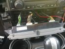
Heater control wiring138 views
|
|
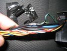
heated seats31 views
|
|
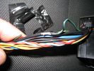
Earth or -Ve connection required under Driver Seat. Cut the green and black and splice into the blac.134 views
|
|
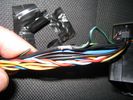
wiring118 views
|
|
Horn Wiring Image58 views
|
|

Horn Wiring71 views
|
|

Thread upload11 viewsImage uploaded in thread 176906
|
|
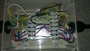
Topside124 viewsWiring from the top, one additional earth added to the internal box after the picture was taken.
|
|
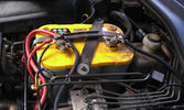
The auxiliary battery21 viewsThe auxiliary battery in the bay.
As the wiring diagram I made shows, there's a wire leading to the fuse box in the rear. (is going through the key-switch)
The second one is going to the fog lights. The smaller cables which should be connected to the head-lights, are connected to the battery.
The third one is going to the compressor (via a switch) (sits before the key-switch)
A fourth one is going to the CB and battery check display (sits before the key-switch)
|
|
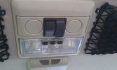
The on/off switches of the multimedia headrests17 viewsThese switches were installed to power on/off the previously installed gamecube and the screens attached to it.
When I removed the gamecube and lately the screens as well, I was clever enough (surprised as well) to leave the switches and all the wiring that I had running around.
They came in handy when I installed the multimedia headrests and are now adding an extra power on/off control of the screens.
|
|
close-up of dome light wiring loom189 views
|
|
Dome light wiring loom197 views
|
|

Series Wiring75 views
|
|
Wiring 15 views
|
|

Intelli Beam Wiring Diagram312 views
|
|
1628 viewsSome of the heavy wiring from the switch pack to the winch motor done.
|
|
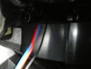
110 viewsview of wires inside dash (from where plug was removed). I ran them through the pre-existing slit in the top of the glove box to wiring loom connector.
|
|
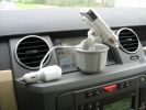
Full setup...562 viewsThis is a side view of that setup. As you can see, all the wiring can be hidden from view in the bottom of the car adapter (The part that goes into the cup holder...)
|
|

Wiring fault189 viewsThe wire and connector that corrodes causing a fault to the key fob locking
|
|
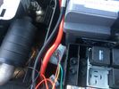
wiring to be sorted10 views
|
|

Centre console and cubby storage removed for wiring loom of rear seat entertainment19 views
|
|

Under-vehicle wiring574 viewsUnder-vehicle wiring on Discovery 3
|
|
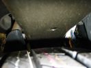
Under body wiring632 viewsUnder body wiring on Discovery
|
|
Xenon Headlamp wiring 115 views
|
|
Xenon Headlamp wiring 226 views
|
|
Xenon Headlamp wiring 319 views
|
|
Can bus wiring repair19 viewsprevious owners repair to a can bus wire near the transfer case module
|
|

With front on ramps check here for water in wiring channel28 views
|
|
Wiring looms and cooling pipes need to be moved out the way12 views
|
|

information and entertainment system (wiring diagram).pdf707 views
|
|

Information and Entertainment System - wiring diagrams13 views
|
|

Infotainment Wiring inc RSE92 views
|
|

128 viewsWiring Diagram for HEVAC-System
|
|
Subwoofer Install275 viewsThe stock sub has 2 sets of wires running to it. Both of these wires lead back to the stock amp.
The new sub only needs two wires - a positive and a ground. So, we just cut the stock wiring harness off the wires in the tail gate and wired them together. On the other end of these wires, we did the same thing.
|
|

Replacement switch from RRS installed on LR3864 viewsThe switch shown is LR part number YUZ500020, the upper rear hatch release switch that is found on the Range Rover Sport.
The switch body is the same switch as on the LR3 except that there is no wiring disconnect on the LR3. Hence when the switch corrodes and requires replacement, the LR solution is to purchase a new handle and license plate light assembly. I instead cut off the old switch and installed a JAE mating connector to the existing wiring and hence just plugged the RRS switch in.
The replacement RRS switch snaps into the same rectangular space in the same manner as the removed LR3 switch, the difference is the JAE male wiring connector.
|
|

Key in Ignition Electrical Wiring Diagram1051 viewsThis shows the key in ignition wiring, (LGW, 1.5D), running from the key lock cylinder to the Central Junction Box, (CJB), thru 5 amp fuse F40P, located in the fuse box behind the lower glove box door.
You can remove the 5 amp fuse and the good news is that the ignition chime will not sound any longer; the bad news is that a bunch of other circuits that rely on knowing if the key is in or out no longer work.
Also note the Transponder Coil D219 reference.
|
|

Most ring26 views
|
|
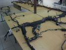
Wiring Laid out shown from other side121 viewsDamaged Disco 3 loom on bottom and new Sport one on top. This angle is as if you were looking at the drivers seat from the front (RHD). You can see the amp wiring centre shot and the rear door wiring to the left all duplicated.
|
|
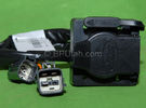
Harness section that runs behind the rear bumper.410 viewsThis is the harness section that clips up inside the rear bumper and includes the circular 7 pin, (6 flat +1 round), NAS socket, and also the 4 pin NAS flat connector.
The two small plug ends connect under the rear left tail light to the harness section that exits from the interior.
The Land Rover part number for the NAS trailer tow kit, (both cables), is YWJ500220.
|
|

Harness that connects inside left rear compartment.445 viewsThis is the harness section that connects behind the left rear interior access panel and exits thru the large grommeted hole to below/behind the left rear tail light.
Note the two rubber grommets on the harness as there is both an interior metal skin and an exterior metal skin behind the left tail light assembly.
The two light grey connectors plug into two existing connectors near the top of the rear left interior access panel. The two darker connectors plug into the second piece of harness.
There is no little separate fuse box either with the NAS spec harness. The fuse box is included with the UK 13 pin dual plug units. If there was a fuse box, it would be on this portion of the harness.
|
|

Thread upload8 viewsImage uploaded in thread 166460
|
|
Thread upload4 viewsImage uploaded in thread 166460
|
|

Thread upload5 viewsImage uploaded in thread 166460
|
|

Thread upload7 viewsImage uploaded in thread 166460
|
|

Thread upload9 viewsImage uploaded in thread 166460
|
|

Thread upload8 viewsImage uploaded in thread 166460
|
|
Thread upload8 viewsImage uploaded in thread 166460
|
|

Thread upload7 viewsImage uploaded in thread 166460
|
|
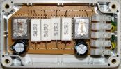
All the components assembled ready for wiring.830 viewsThe 5watt resistors get fairly hot, be careful not to have them touching the relay case or use a larger box for yours.
|
|
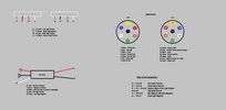
Thread upload8 viewsImage uploaded in new thread
|
|
Thread upload6 viewsImage uploaded in thread 130779
|
|
Thread upload7 viewsImage uploaded in thread 130779
|
|
Thread upload15 viewsImage uploaded in thread 119434
|
|

134 views
|
|
![Filename=Lighting_diagram[1].jpg
Filesize=26KB
Dimensions=952x556
Date added=15.Jan 2009 Lighting_diagram[1].jpg](albums/userpics/12442/thumb_Lighting_diagram%5B1%5D.jpg)
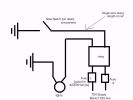
ON OFF ON Spotlight Wiring Diagram by UNG87 views
|
|
88 views
|
|
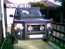
Wiring harness for Hella 4000 Compacts260 viewsWired directly to the battery, all tucked away neatly now but can\'t find the picie
|
|
Looks much better now - still have the wiring and dashboard hacking to do423 views
|
|

wiring audio information and entertainment system1179 viewswiring audio information and entertainment system1
|
|

wiring audio information and entertainment system170 viewswiring audio information and entertainment system
|
|
482 views
|
|
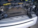
19mm wiring loom in trough behind bumper and in front of rad792 viewsThe 19mm wiring loom is large enough that a maximum of six 6mm air lines can be fished thru as required. The loom runs from the FASKIT panel located in the engine compartment behind the left front headlight, down and across in front of the rad and then down to the front axle valve block located behind and below the right fog light.
|
|
414 viewsHere is the left rear cubby box with the TM-D700A bolted inside. I also drilled a hole in the bottom of the cubby for antenna, GPS, and power wiring, and a hole in the front for control, microphone, data, and audio cabling.
|
|
388 viewsCompleted Install of Control Panel. Wiring goes up into headliner, over curtain airbag on left hand side, and down the B pillar.
|
|
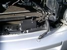
Battery Maintainer switch box and connector 722 viewsThe Hammond box contains a DPDT toggle switch with centre off. The Positive and Negative from each battery feeds to the switch. Depending on the setting of the toggle, (full left, full right,or centre off),the respective batteries connect into the pigtail that can stick out thru the grill when one wishes to connect the charger.
This allows one to charge each battery independently via a suitable battery maintainer. I use a CTEK unit that feeds a maximum of 3.3 amps at 14.4 or 14.7 VDC, depending upon setting. The wiring therefore allows for a slow recharge of either of the batteries separately if either one requires such.
|
|
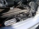
Battery Maintainer switching box plug and CTEK Multi US 3300 charger. 706 viewsThe CTEK Multi US 3300 maintainer is just sitting there for the picture. In addition to topping up both batteries, the CTEK can provide power such that if the batteries were completely dead, there would be power to the door locks and hence, one could most likely still gain access via the remote once the starting battery charged up a bit.
The Land Rover recommended method is via the hidden key hole which is mechanical, however that presumes the mechanism is not frozen from lack of use. As such, the manual lock should be exercised at least once a year to ensure that it still functions.
The blanking plug sitting on top of the plastic box is of the GM Weather Pack series. That is what I like to use for vehicle wiring that is subject to moisture, (or not).
|
|
Boot lighting panel, wiring side up 281 viewsThis shows the back side of the plastic cover panel on which the two LED lights are mounted.
Also of note is the SPST rocker switch to switch the new lights off independent of the the Land Rover W5W light.
The new light pair will only power up if the Land Rover light is powered and hence dims and automatically goes off along with the Land Rover light.
The Black wire is ground, the Purple wire is +12VDC.
|
|
Dust Seal duct taped back together 2281 viewsThis shows the dust seal duct taped back together; also the surplus wire rope exiting from the actuator area prior to being cut to length.
I do not think the sticky plastic membrane is a dust seal, but more of a cable protector to cover up the wiring bundle that is effectively sticking to the underside of the flexible membrane.
|
|

NAS 7 Pin Round Socket + 4 Pin Flat Socket oriented as installed.752 viewsThis is the layout you see when you look into the NAS Land Rover sockets as installed at the rear of the LR3/4. The flat 4 pin socket is located under the round socket.
Wiring order is relative to the slot on the round socket, and hence the same as the other jpg where the slot is shown at the top.
The CJB monitors the front and rear turn signal lamps and can detect if more than four lamps are fitted, (the side turn signal lamps are not monitored). This is another reason for using genuine LR bulbs as off shore bulbs can have varied and out of spec resistance values.
When a trailer is detected, the trailer warning indicator in the instrument cluster is supposed to flash green in synchronization with the turn signal indicators.
If one or more of the turn signal lamps on the vehicle or the trailer are defective, the trailer warning indicator will cease to flash any longer. This is to alert the driver to probably bulb failure.
If the trailer has LED lamps installed, and no LED adapter circuitry is used, most likely the trailer will not be sensed and systems such as the backup sensors will not be disabled.
|
|
Plastic cover and Box back on in Front of Radiator 637 viewsThe wiring loom is below the cover - nothing is crushed or distorted and all fits back together OK. The black plastic box with the DPDT, (centre OFF), toggle switch is to tie the battery maintainer to each of the two batteries per the Traxide Dual battery install. I can also get power to the power door locks if all fails.
|
|

Component Names related to Power Window Wiring Diagram283 views
|
|

LR3 Electrochromatic Interior Rear View Mirror wiring diagram.852 viewsIt seems that there are two fuses, F69P and F5P that provide power for the interior rear view mirror. Ten amp F5P is a feed off the reverse gear relay and inhibits auto dimming when reverse is selected. Five amp F69P provides power to the auto dimming circuits and the garage door opener function if optioned.
The pdf can be downloaded and printed out. For on screen viewing, right click on the pdf and select the Rotate Clockwise button.
|
|
19 mm wire, (tubing), loom rising from below at left headlight656 viewsFrom the FASKIT panel, five air lines fit in the 3/4" (19mm) wiring loom and feed to the front air valve block located behind and under the right front fog light.
|
|
Wiring (tubing) loom at left headlight showing FASKIT panel 584 viewsThis shows the wiring (tubing) loom and FASKIT panel mounted to left wing. The loom moves a a couple of inches (50mm) towards the bottle once the headlight is put back in as there is not enough free space for the loom as located. The FASKIT panel is just visible at the top left corner of the picture.
|
|
Wiring, (tubing), loom exiting temporarily from the front right fog light.569 viewsThe front axle air valve block is located just behind and below the fog light. Access to the valve block is by removing the right front fender liner, (or the bumper). The FASKIT lines are attached to the left and right front air spring lines at this location; also compressor air is taken from this location as well. Cutting the lines at as few different locations makes it easier to find leaks at a later date. As above, five 6mm air lines run from the FASKIT panel to the front axle air valve assembly and run within the loom. Two pair of the lines are for control of the air springs, and the fifth line taps the air supply at the valve block assembly off the compressor. This will be the air source line rather than tapping in directly to the high pressure air tank.
|
|

LR3-Wiring_exterior_lighting72 views
|
|
a few items being built in behind cover panel.442 viewsred inverter will have fluch mount plugs, air outloet will be flush, guage with window in lower pop-panel and switches and fuses for all rear items behind popout panel.
12v sockets being added as well, high and low.
|
|
wiring progress423 viewslots torn out that somehow goes back together
|
|

Thread upload42 viewsImage uploaded in thread 47507
|
|

LR3 Air Conditioning High Line electrical wiring diagrams1465 viewsThis 7 page pdf shows the wiring for the Heater/AC both front and rear.
|
|

Air Suspension Wiring Sheets3037 viewsThese two sheets show the wiring and fuses related to the operation of the air suspension system. Fuses F3E, F26E, and F35P are shown as well as the interior up down switch and the wheel height sensors.
As with all pdf's, you can rotate them to view plus download and or print out as you wish.
|
|

Console Gear Selector Wiring Diagram960 viewsThis is a 3 page wiring diagram centered around the console located gear selector.
|
|

LR3 Brake Wear Sensor Wiring1517 viewsThis 1 page wiring diagram pdf shows that both the front and rear brake pad wear sensors are part of a closed series circuit to ground.
In operation, when all is good, the series circuit is grounded and the amber brake wear warning indicator on the instrument panel is not illuminated.
When the pads on one wheel, either the left front, or right rear, become too worn, the respective sensor is "cut" which results in an open circuit condition. This causes the dash brake wear indicator to illuminate.
The circuit is like the old style Christmas light strings where one burned out bulb caused the whole string to go out.
A quick field fix to get the dash light to extinguish in lieu of replacing the sensor and pads etc is to disconnect the brake pad wear sensor and short across the two open conductors of the vehicle side connector plug. This of course means you now have a normal vehicle, one of the thousands that do not feature brake pad wear information systems.
|
|

Door Lock Wiring Diagrams1730 viewsNear the bottom of this 5 page pdf on page 224 are shown the pushbuttons and locking mechanisms for the rear hatch and tail gate.
The pdf will open vertically but you can download and print it out or just rotate the image clockwise by right clicking on your screen and selecting the "Rotate Clockwise" button.
|
|

Power Door Lock wiring diagrams530 viewsI thought I would include this 5 page power door lock wiring diagram pdf here as well.
When the pdf loads, if the views are vertical, it may be that you can right click on your mouse and a box will come up that will allow you to rotate the views clockwise so that the sheets are horizontal. Alternatively you can download the file and print each sheet yourself.
|
|

Power Door Lock Wiring694 viewsAbove is a 5 page, (pages 222 to 226), pdf wiring diagram for the power door locks for the LR3.
You can download and print as required. For on screen reading, use the right click rotate feature.
Additional pdf's regarding Locks can be found within the Gallery under the Power Windows and Door Lock Circuits heading.
|
|

Engine and Transmission Electronic Controls Wiring Diagram996 viewsThis 20 page pdf shows the wiring for the electronic controls for the engine, transmission and transfer case.
|
|

Power and Heated Seats Electrical Schematic979 viewsThis 6 page pdf shows the wiring for the power adjustment of the front seats and seat heating for all the seats.
Re seat movement or the lack of, not only are there four related fuses, two 30 amp and two 5 amp, (one of each per seat), there are are two separate ground wires, perhaps of more significance than the power, if all movement on either side quits.
|
|

Horn Wiring Circuit LR3578 viewsThe is the wiring diagram for the dual horn circuit.
The Horn Relay, (R133), is not a big black thing hidden somewhere but instead what is called a FET, (and it is hidden)!
This is a Field Effect Transistor that is built into the circuit board that is mounted to the back of the fuse box that is located behind the lower glove box door on the passenger side of the 3. The related 15 amp fuse, 12P, is mounted in this fuse box and is often called F12P, where F is for fuse, and P is for Passenger compartment.
This is to help differentiate from another fuse and relay box, (the usual kind), that is located beside the starting battery in the Engine compartment. FxxE is often used in the naming of those fuses.
|
|

Mirror - power fold pivot and pan/tilt/heat wiring42 views
|
|

Stop Light Lamp Circuit pdf2491 viewsThis pdf shows the brake light circuit for the NAS LR3.
Note that power for the brake light bulbs can come either thru the brake light switch power feed /contacts plus also from the Hill Decent Control, (HDC), system relay located within the Central Junction Box, (CJB) - yes two separate sources of power for the brake light bulbs. This would tend to explain how a brake light circuit concern shows up as a hill decent fault message; also why lesser vehicles without hill decent braking mechanisms, (HDC), never display this sort problem when a brake light bulb or switch acts up. You never have a problem related to a system that does not exist.
Additional evidence of the relationship of the HDC and the tail light circuit is demonstrated by when the HDC actually acts to slow the 3 down, the brake lights automatically illuminate even if the slowing action was merely retarding the engine speed or shifting to a lower gear, (in other words, no foot on the brake pedal).
There is also a tie in to the Cruise Control and hence a failing brake light switch can affect cruise operation or just create false Cruise Control messages. To further complicate the issue, while there are no messages generated, operation of the radiator electro viscous fan can also be negatively affected by the fouled set of secondary contacts within the brake light switch. This is all because the NC contacts within the brake switch send misleading messages to the ECU.
While the ground wire design is similar to other vehicles, note the grounds for the brake light filament and the reverse light filament are common on each side. That means that if one has a non functioning brake light on one side, the reverse light may not also work or that some problem with the reverse lights could back feed into the brake lights. This situation while unusual, can result when grounds are corroded probably due to swimming in rivers and creeks or just routine driving in a marine environment.
|
|
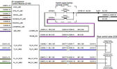
Thread upload5 viewsImage uploaded in thread 175498
|
|

Thread upload15 viewsImage uploaded in thread 167285
|
|

Heated Windscreen Wiring Diagram408 viewsThis single page pdf is the heated windscreen wiring diagram. You can rotate the view by right clicking on the pdf and of course it can be printed out as well.
Relay R208 in the pdf is relay R9 in the Engine Compartment fuse box. Note both 30 amps fuses, F15E and F18E, also located in the Engine Compartment fuse box. If one side of your windscreen does not heat, the problem may be one of the two fuses.
|
|
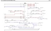
Thread upload4 viewsImage uploaded in thread 120453
|
|

16 views
|
|

Disco3 Wiring147 views
|
|

D3 Wiring Diagram102 views
|
|

Wiring Diagram167 viewsLR3 Wiring Diagram
|
|

47 views
|
|

Maf 126 views
|
|

MAF 221 views
|
|
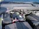
Main Battery showing aux cable feed running off positive battery post.776 viewsThe black wiring loom around the battery cable to the aux battery was a part provided with the Traxide kit. My goal was to run the cable low enough such that the battery box cover would go back on as previous.
Note the hole drilled in the side of the battery box such that the new cable could thread thru to allow the battery box top to still fit the same as prior to the addition of the cable to the auxiliary battery.
|
|

Thread upload16 viewsImage uploaded in new thread
|
|

NAS 7 plus 4 pin LR3 Trailer wiring, battery end. 548 viewsThis is the LR wiring diagram from the engine compartment battery location to the Electric Brake Controller connector, C2590, located under the dash near the brake pedal.
|
|

NAS 7 plus 4 pin LR3 Trailer wiring, trailer end. 498 viewsThis is the LR wiring diagram showing the conductors from the the Trailer Brake Controller connector, C2590, back to the rear combo NAS 7 plus 4 pin sockets.
|
|

NAS Trailer Wiring Colour Code366 viewsThis is a common wiring colour code for trailer wiring in North America. Some vehicle manufacturers follow the code for at least some of the functions.
|
|
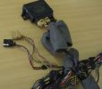
Missing PDC connector114 viewsThe front PDC sensor connector and wiring to the front had been removed.
|
|
Thread upload5 viewsImage uploaded in thread 198300
|
|
82 views
|
|

Thread upload14 viewsImage uploaded in thread 189581
|
|

Thread upload30 viewsImage uploaded in new thread
|
|

ON OFF ON Spotlight Wiring Diagram by UNG119 views
|
|

Thread upload6 viewsImage uploaded in thread 126959
|
|
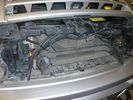
radar detector wires tucked up high426 viewsThe orange ties hold wiring sockets for floodlights (to be installed). Red tie holds excess wire for radar detector.
|
|
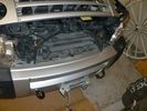
wires tied up tight542 viewsThe Orange ties hold wiring sockets for floodlights (to be installed). Red tie holds excess wire for radar detector.
|
|
Re-wiring of 2nd aux battery130 views
|
|
Wiring from spare battery70 views
|
|

Paddle shift wiring49 views
|
|
Thread upload5 viewsImage uploaded in thread 175065
|
|

EPB wiring diag46 views
|
|

Thread upload13 viewsImage uploaded in thread 65718
|
|

Thread upload40 viewsImage uploaded in new thread
|
|

Thread upload46 viewsImage uploaded in new thread
|
|

Front PDC wiring35 views
|
|

17 views
|
|

15 views
|
|
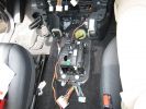
286 viewsPicture of the floor console removed. The wiring moving along from the bottom of the picture forward is power from the rear power socket, and audio from the aux port.
|
|
280 viewsHere is the center console with the support pulled away. You can see the wiring for the HD and XM radios working their way through the console and over to the lower glove box.
|
|
248 viewsThe two installed modules with preliminary wiring for testing.
|
|

Power Window Wiring Diagrams416 viewsThis pdf shows the power window wiring diagrams which are also shown as jpgs 1,2 and 3 below.
|
|
429 viewsRear compartment with my additional wiring and fuses.
|
|
Possible Rack Light Wiring183 views
|
|

radio wiring diagrams84 views
|
|

Rear PDC wiring16 views
|
|
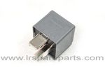
Air Compressor 70 amp replacement relay1393 viewsThere is a software update, 09 April 2010, LTB00270, for the compressor which reduces the shut down pressure to about 205 psig (14 bar). The update is usually done when changing to a new compressor and also includes replacing the R7 relay in the engine compartment fuse box, 07 DEC 2010 LTB00331.
The newer grey case coloured relay, part # YWB500220, shows to be rated at 70 amps, (the relay, not the compressor), however the previous black case coloured relay also indicates 70 amps.
Both the new and replaced relay show on their wiring diagrams to have a parallel voltage spike resistor, (probably 560 ohms), across the coil terminals, #1 and #2. This means one does not just replace the relay with any four prong 70 amp ISO sized relay that one happens upon.
One presumes the grey relay is either upgraded or just being installed for good measure. The relay is common on Ford Fiesta for the seat heater relay, Ford part number 5M5T 14B 192 EA; also Volvo, part number 30765034. The Tyco part number moulded on the grey body is V23136-J4-X62.
|
|
Thread upload34 viewsImage uploaded in thread 44435
|
|
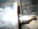
Reservoir Air In fitting installed 1660 viewsSchrader valve installed. Shop air can now be introduced into the tank to facilitate the raising of the 3 when there has just been a failure of the onboard air compressor rather than the electronics or valve block wiring etc.
Air could also be sourced from this point, however the purpose of the modification is air in, not air out as the air pressure normally runs above 200 psig, too high to be safe for routine use unless a pressure reducing regulator is added per the Mitchell Bros kit.
|
|

Roof lining wiring47 views
|
|

FBH Wiring Diagram30 views
|
|
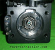
NAS 7 pin + NAS 4 pin Flat Trailer Socket308 viewsThis is the vehicle end of the NAS trailer harness that is located behind the removable plate centered within the rear bumper by the towing loop. Re the four pin flat connector, from the bottom, the exposed bare lower pin is the ground, usually the White wire on a NAS trailer. The next pin up is normally a Brown wire on a trailer and is for the Tail Lights. The third pin, normally a Yellow wire, is the left signal light; the top pin, normally a Green coloured wire, is the right signal light.
Re the round connector, from the notch in the plastic surround, clockwise, the first blade is ignition controlled +12VDC battery power, (only alive when engine running), and on the Land Rover factory harness is an Orange wire; on a NAS trailer, usually Red but perhaps a Black wire.
Next blade clockwise at 3:00 o'clock above, is the Right Turn signal light, a Green wire on the LR harness, and also on a NAS trailer.
At 5:00 o'clock, the next blade is for the Electric Brakes and is Blue on both the LR harness and on a NAS trailer.
The Ground wire is next, White on both the LR harness and on a trailer.
At 9:00 o'clock above, is the Left Turn signal, Yellow on both the LR harness and on a trailer.
The last blade to the left of the line up notch is the Tail Light circuit. On the LR harness, the wire colour is Brown with two White stripes and on a NAS trailer, Brown.
The centre pin is for the Reverse Back Up lights and is Black on the LR harness and often Purple on NAS trailer wiring but can be Black also.
Note that when the socket assembly is installed on the 3, the notch in the plastic surround is on the left - that is rotated 90 degrees anticlockwise to the picture above. In other words, When installed on the 3, the 4 pin flat connector lays horizontal and is located below the round socket.
|
|
Clock spring wiring pinout ish69 views
|
|
Wiring diagram heated seat 73 views
|
|
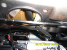
Wiring heated seat70 viewsThis picture is taking from behind the driver seat underneath.. the black cable that goes up in the hole is the wiring for the heat elements. There is a connector on the other end, not visible in this pic.
|
|
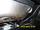
75 viewsup close wiring to the seat
|
|

wiring taped up61 views
|
|

Extra wiring for height sensor53 views
|
|
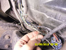
wiring snapped of65 views
|
|

Air susp failt wiring59 views
|
|

Logic7 amp wiring38 views
|
|
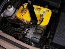
Installed and wired863 viewsShows the wiring loom to the isolator, the feeds (fused link) to the rear outlets and the other feeds are for the battery meter
|
|

pdf wiring diagram147 views
|
|

Seat Heater Element wiring diagram34 views
|
|
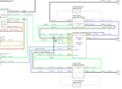
Thread upload24 viewsImage uploaded in thread 108198
|
|

Thread upload1 viewsImage uploaded in thread 140874
|
|

Something for you die hard Rover fans178 viewsI'm sure you may need this on your travels!!
courtesy greeni expedition portals..
|
|
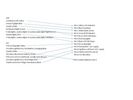
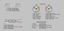
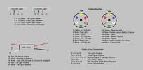
13 pin to 7 pin trailer socket wiring169 views
|
|
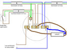
Thread upload1 viewsImage uploaded in new thread
|
|
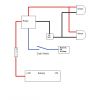
Spot or Driving Lamp Wiring Diagram312 viewsFor wiring non-LR lamps
|
|

Thread upload8 viewsImage uploaded in thread 190636
|
|
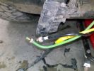
Suspension Valve Block & Wiring removed for Re-Routing141 views
|
|
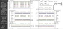
Thread upload0 viewsImage uploaded in thread 178371
|
|
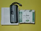
Upper Hatch Release Switch LR Part Number YUZ500020676 viewsThis is the Range Rover Sport switch, Land Rover part number YUZ500020, as it comes out of the box. Note the JAE, (Japanese Aviation Electronics), male wiring connector installed on the end of the power lead.
The rubber cover of the switch is sealed to the plastic body of the switch whereas in the previous switch design, there was no sealing. Also the replaced switch was hard wired into the same harness as the license plate lights - no JAE connector in other words.
|
|
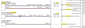
Tailgate Wiring44 views
|
|
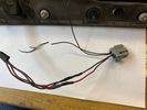
Thread upload3 viewsImage uploaded in thread 195222
|
|

Tekonsha P3 Brake Controller 90195 to Ford 3035-P wiring adapter plug311 viewsThis two page pdf is the general instruction for hooking up the Tekonsha part number 3035-P adapter cable between a Tekonsha P3 controller and the existing Land Rover/Ford plug, (called C2590 in the Land Rover wiring diagrams), that is hidden above the brake pedal.
The "Ford" plug, (C2590), is grey and is stuffed up above the brake pedal arm.
Mount the P3 controller appropriately and then connect one end of the custom cable to the P3 and the other to the "hidden" plug.
You will now have power for your trailer electric brakes in the round socket at the rear of your LR3; also no computer update from the Land Rover T4 unit is required. For once, it is plug and play.
If however, your trailer has LED tail lights, you may have trouble with the flashing of the trailer signal lights or non recognition by the 3 that a trailer is connected. As such, the little green trailer signal will not illuminate when a trailer is connected and the signal lights are used. This can affect the shifting of the transmission and much to your annoyance, the backup sensors will still be functioning rather than being auto disabled.
|
|
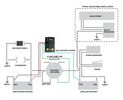
Tmax Wiring55 views
|
|
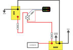
Thread upload10 viewsImage uploaded in thread 128464
|
|

12 views
|
|
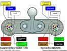
7 pin tow electrics16 views
|
|

22 views
|
|

Thread upload7 viewsImage uploaded in thread 136443
|
|
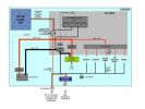
trailer wiring diagram212 views
|
|
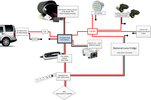
Thread upload31 viewsImage uploaded in new thread
|
|
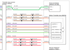
Transfer Box Wiring25 views
|
|
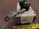
Radio Noise Filter Transmission Electronic Control Unit913 viewsThe jpg shows part number LR020488, a noise suppression capacitor located underneath on a bracket on the right side of the transmission forward of the selector shaft lever. The suppressor is connected to the transmission wiring harness and prevents solenoid operating noise affecting the audio system.
Failure of the capacitor is most often discovered as a result of either black smoke from below and or the blowing of 10 amp fuse F30E located in the engine compartment fuse box. This fuse protects the power circuit to the Transmission Engine Control Unit. When the fuse blows, the engine will still run however you have no gears, hence movement of the 3 is inhibited.
Anything over eight years in service is considered good capacitor life. If the capacitor does fail and fuse 30 blows, a quick fix is just to disconnect the capacitor and replace the fuse.
The capacitor might be missed by the DOT/FCC but the 3 does not seem to mind. With the filter disconnected, solenoid noise might be heard on some radio stations but at least the 3 would be in motion.
|
|

Thread upload19 viewsImage uploaded in thread 1189
|
|

upper tailgate5 views
|
|

Thread upload34 viewsImage uploaded in new thread
|
|

LR3 Vehicle Dynamic Suspension109 viewsLR3 Vehicle Dynamic Suspension wiring diagram
|
|
Thread upload4 viewsImage uploaded in new thread
|
|

Thread upload9 viewsImage uploaded in new thread
|
|
Thread upload10 viewsImage uploaded in new thread
|
|
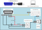
Thread upload5 viewsImage uploaded in thread 154824
|
|
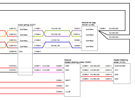
Thread upload6 viewsImage uploaded in thread 153574
|
|
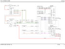
Thread upload9 viewsImage uploaded in new thread
|
|

Thread upload9 viewsImage uploaded in thread 153574
|
|
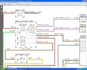
windscreen wiring321 views
|
|

New Wiring Overlaid98 viewsSport loom gives me length info to position replacement connector and its wiring in. Her you can see the new wires lying over the top of the cut of ones.
|
|
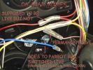
Wiring loom for the parrot186 views
|
|
23 views
|
|
31 views
|
|
22 views
|
|
32 views
|
|
21 views
|
|
28 views
|
|
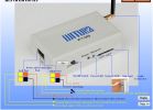
WT009 Wiring103 views
|
|

Thread upload25 viewsImage uploaded in thread 118626
|
|

Root of all evil, err, what makes the DS/LR3 go!431 views
|
|
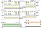
Amp wiring97 views
|
|
Thread upload17 viewsImage uploaded in thread 113428
|
|
Thread upload5 viewsImage uploaded in thread 175355
|
|

Thread upload2 viewsImage uploaded in thread 187958
|
|

Thread upload1 viewsImage uploaded in new thread
|
|

Thread upload3 viewsImage uploaded in new thread
|
|

3 views
|
|

111 views
|
|

Thread upload1 viewsImage uploaded in thread 189587
|
|

Thread upload10 viewsImage uploaded in thread 131361
|
|
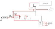
Thread upload5 viewsImage uploaded in new thread
|
|

Modified Wiring diagram for the added electrical bits28 viewsI made this wiring diagram during the cleanup I did lately.
I completely removed some 'old' electrical bits I had installed and used the occasion to document every left and new part.
|
|

LR3 Wiring Diagrams17 views
|
|

Thread upload34 viewsImage uploaded in new thread
|
|
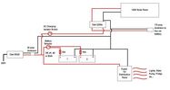
Thread upload4 viewsImage uploaded in thread 132429
|
|
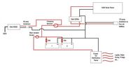
Thread upload9 viewsImage uploaded in thread 132429
|
|

Thread upload10 viewsImage uploaded in thread 131361
|
|
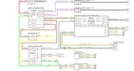
Thread upload11 viewsImage uploaded in new thread
|
|

Thread upload57 viewsImage uploaded in thread 120453
|
|
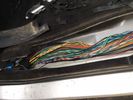
Thread upload13 viewsImage uploaded in thread 54235
|
|

Thread upload1 viewsImage uploaded in thread 178588
|
|
Thread upload1 viewsImage uploaded in thread 189587
|
|

Spot lamp / driving light DIY install wiring diagram98 views
|
|
|
|
|
|
|