| Search results - "System" |

Thread upload6 viewsImage uploaded in thread 143984
|
|
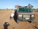
08 D3 stranded with a seized smoking wheel315 viewsAbout 1 hr after replacing the blown tyre, strange noises emanated from the stability control system and speed dropped off. Then I looked in the rear view mirror, and noted a cloud of dust along with a whiff of black smoke. This led to a very quick stop (no traffic on this route for over a week, so no worries about having to signal exiting the road). Took a look and WOW. The right rear wheel was glowing a dull red colour, and burning rubber smoke was wafting from the red glow over the fuel lines.
|
|
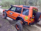
COVER SHOT FOR TOTAL OFF ROAD114 viewsG WAGEN AXELS FITTED WITH HYDRAULIC FRONT + REAR DIFF LOCKS + EXTREAM SUSPENSION SYSTEM FRONT + REAR WARN WINCHES.
|
|

15 Exhaust System18 views15 Exhaust System
|
|

Load retention system fitting instructions47 views
|
|
49 views
|
|
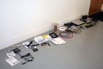
01313 viewsAll the new junk laid out on the floor.
Kenwood KOS-V1000 AV Controller
Kenwood KCA-iP500 iPod Control Interface
Kenwood KOS-L702 Monitor
Kenwood KCA-BT200 Bluetooth interface
Kenwood KNA-G510 Add-on navigation system
|
|
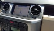
ta-dah! the final result36 viewscomplete GPS satNav system, with iGO software and ALL maps from europe 2012, including POIs speedcams, and personalized land rover skins
|
|
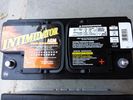
Deka 9A49 AGM Intimidator327 viewsThe Deka 9A49 AGM Intimidator makes an excellent primary battery alternative to the factory or Interstate. Made in US of premium quality. This is an excellent match with the Traxide system w/another Deka or Yellow Top optima.
This will behave properly in your D3/4 LR3 with slightly less wear and tear on your alternator.
|
|

Traxide System4 views
|
|

Thread upload8 viewsImage uploaded in thread 202510
|
|

Thread upload8 viewsImage uploaded in thread 205377
|
|

41 views
|
|
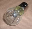
Land Rover Stop Tail Light dual filament bulb nominal 12 volt 21 / 5 watt filaments1427 viewsThis is the Land Rover part number 264590 dual filament bulb, (P21/5), that inserts into the upper two tail lamp receptacles. In the upper one, both filaments function, in the lower one, only the 5 watt tail light filament functions.
I regard it as not a good practice to routinely switch bulbs when the tail light filament, (5 watt), burns out on the lower bulb. The broken filament can jiggle over onto the brake light filament, (21 watt), and short the circuit to ground or something else not predicable.
There are also arguments to say that quality control is better on the Land Rover marketed bulbs than say far east sourced bulbs. Filament construction, and hence resistance can vary and mislead the current sensing circuits monitoring the signal light systems. Also when the bulbs are properly installed, all filaments should be standing vertically and not at any slope.
These are the sort of obscure circumstances that can lead to false trouble messages on the display, dropping to the stops, and subsequent concerns - all over a tail/signal light bulb.
For example, the filament life of both the tail light and the brake light filaments in the P21/5 bulb is significantly less than the USA common 1157 dual filament bulb, (1000/250 vs 5000/1200 hours); brightness in the P21/5 is a bit more, (3cp/35cp vs 3cp/32cp where cp is candle power), but current consumption is oddly less, (0.44a/1.86a vs 0.59a/2.10a where a is amps). It is the quest for efficiency vs maintenance trade off.
|
|
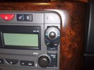
position of buttons for Parrot phone102 viewsthis can be put basically anywhere as it connect via bluetooth to the rest of the system. It is self powered (lithiam battery in it) so just stick it anywhere with no requirements for finding a live wire etc
|
|

ZF 6HP26 Transmission Cooling System Description and Operation2936 viewsThe five page pdf details the operation of the cooling system as related to cooling engine oil, transmission oil and providing hot water to the cabin heating system.
|
|

308-Four-Wheel-Drive-Systems-TransferBox60 views
|
|

Air Distribution and Filtering Systems2083 viewsThis is 3 page pdf with coloured drawings of the air distribution ducting for the front air system.
Also included is a sketch of the pollen filter location within the front heater ducting. Note that two types of filters are available: a) the cheaper dust/pollen filter and b), the activated carbon filter that removes smells from the air. Installing the more expensive activated carbon filter means you never smell a cattle truck or chicken farm again. It really works.
|
|

Air Conditioner Specifications 4.4L V81569 viewsThis 2 page pdf is just the specifications for the AC system. The refrigerant type is R134A.
Note that when topping the system up, it can be a good idea to include some of that ultra violet light dye that will glow to show leaks and loose fitting.
|
|

Rear Area Climate Control System1161 viewsThis 14 page pdf describes how the rear heating AC system is supposed to operate in conjunction with the front system.
The air transfer ducts are shown as coloured sketches as is the air flow within the rear blower setup.
|
|

Air Conditioning and Heater Control Components2425 viewsThis is a 21 page pdf that really explains how the air system is supposed to work. Discussed are the exterior ambient air sensor, where and how it operates; the interior temperature sensor as well as humidity sensor.
|
|

33 views
|
|

Thread upload25 viewsImage uploaded in thread 188003
|
|

Entertainment System Wiring Diagrams2331 viewsThe 12 page pdf has the wiring diagrams for the low and high line "radio" and various components such as the amplifier, phone modules,NAV display, antennas and satellite radio and TV.
|
|

Alarm System description and Operation1052 viewsThis 9 page pdf explains in detail how the anti-thief, (alarm), system is supposed to operate. The system uses the door ajar switches to provide alarm system signals; as such there are few separate contacts related to the alarm system only.
Page 6 of 9 is of particular interest as it describes the trigger log that is accessible with the dealer T4.
|
|

GPS NAV system components and operation999 viewsThis 16 page pdf describes the operation of the GPS navigation system and provides pin outs and equipment layouts. The GPS antenna amp and location is also shown.
|
|

4 Suspension System15 views4 Suspension System
|
|

Siemens VDO Piezo Common Rail injection PCR 2.321 viewsAfter sales info and exact system discription.
Also fault finding and repair.
This is for Ford 3litre 4 cyl. engine ,Ranger 3.0 TDCI, but Disco 3 is the same with 6 cyl.
|
|

6 Brake System18 views6 Brake System
|
|

7 Steering System13 views7 Steering System
|
|

8 Engine System - General Information17 views8 Engine System - General Information
|
|
Thread upload6 viewsImage uploaded in thread 142542
|
|

anti theft system43 views
|
|

Nav System Error Message20 viewsThis is the error I got onscreen after trying satnav upgrade from a dodgy copy. Same error then using old disc. Solution was to use a 'good' copy or the same type as the duff upgrade disc.
This isn't a duff photo - the screen really does have a double image of the text.
|
|

Thread upload15 viewsImage uploaded in thread 64916
|
|
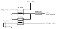
Thread upload19 viewsImage uploaded in thread 125218
|
|

Brakes Description and Operation2229 viewsThis is a 17 page pdf that describes the operation of the various braking systems: the ABS, CBC, DSC, EBD, ETC, EBA, EDC, and HDC. Also discussed is the yaw rate and lateral acceleration sensor as well as the steering angle sensor.
|
|

Brake Light Switch, Find, Remove, and Install Instructions 7851 viewsThis is a two page doc outlining where to find the brake light switch, how to remove it, and then install the new one.
Note, do not move the brake pedal when removing or installing the switch. Let the brake pedal hang where it wants to. The switch design is actually cunning, and as such is supposed to make the removal and install fool proof. Hence if you think too much about it, you can wreck the new switch.
If you want to inspect the interior of the switch, wait until you have removed the old switch. You can then just unsnap the blue from the white to get it apart. Inside, the switch is quite simple, (no circuit boards), but it will probably show black dust from failing contacts.
I think the reason the switch fails is that the Normally Open, (NO), contacts of the brake light contacts were made too light to carry the current load for make and break of the tail light filaments. I also think the black dust created then fouls the Normally Closed, (NC), second set of contacts for the ABS circuit. As such, the Normally Closed contacts become intermittent in operation and display as a fluctuating open and closed circuit condition to the ABS system when the ABS should be seeing a steady closed circuit. Hopefully the replacement switch contacts are more robust and may be as I recently replaced my switch again just as a matter of maintenance. While in a redesign, ideally the NC contacts should be sealed or at least separated from the NO contacts, when I inspected the removed switch, this time there was no black dust present.
Probably the removed switch will have a Land Rover oval logo moulded into it, the new one, FOMOCO.
|
|

Coolant System59 views
|
|
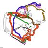
Cooling System59 views
|
|
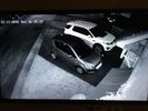
HIKVISION 4mp System45 views
|
|

Coolant - Draining Refilling133 views
|
|

23 views
|
|

Thread upload4 viewsImage uploaded in thread 206753
|
|

Cooling system hoses - 4.4L petrol V81108 viewsThese are the cooling system hoses on the 4.4L petrol V8. The little odd shaped bleeder hose, (LR006158), shown in the top right hand corner can give problems. There is a plastic tee with a threaded air bleeder outlet located in the middle of the hose. The plastic tee can or will fail due to I guess heat distress.
A BIC pen can serve as a field fix, however for your parts kit, a nominal 3/8" ID hose size brass hose barb inline connector plus a couple of hose clamps is suggested. Better yet is a threaded hose barb brass coupling or a tee and bleeder valve to allow bleeding of the line. Land Rover now makes the plastic bleeder valve that breaks available as a separate part, # LR027661, where 0 is a zero. As such, one can now purchase that part only for addition to your field fix parts kit.
|
|
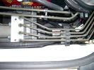
CounterAct Power supply mounted under brake lines.194 viewsThis top view shows where I located the power supply. It is attached with 3M sticky to the black plastic surface that is located under the brake lines.
When the system is operating properly, the red LED pulses about twice per second.
Some users claim they can hear a very slight hum or whine coming from the unit. My unit seems silent.
|
|
Thread upload3 viewsImage uploaded in new thread
|
|
Thread upload3 viewsImage uploaded in new thread
|
|

Thread upload0 viewsImage uploaded in new thread
|
|

Thread upload3 viewsImage uploaded in new thread
|
|

Thread upload0 viewsImage uploaded in new thread
|
|

Thread upload0 viewsImage uploaded in new thread
|
|

Thread upload1 viewsImage uploaded in new thread
|
|
Thread upload6 viewsImage uploaded in new thread
|
|
Thread upload1 viewsImage uploaded in new thread
|
|
Thread upload0 viewsImage uploaded in new thread
|
|
Thread upload2 viewsImage uploaded in new thread
|
|

Thread upload1 viewsImage uploaded in new thread
|
|

Thread upload0 viewsImage uploaded in new thread
|
|
ctek charge system23 views
|
|

056232 viewsP0562 SYSTEM VOLTAGE (ENGINE SIDE) TOO LOW
|
|
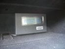
Genesis digital battery system - monitor in top glovebox323 views
|
|
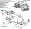
Thread upload20 viewsImage uploaded in new thread
|
|
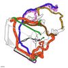
Thread upload22 viewsImage uploaded in new thread
|
|

D3 infotainment38 views
|
|
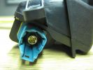
D4 Rear camera connector 142 viewsThis type is used on surround camera system.
|
|
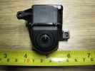
D4 Rear camera front view147 viewsUsed on surround camera system.
|
|
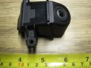
D4 Rear camera side view127 viewsUsed on surround camera system.
|
|
55 views
|
|
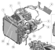
D4 Cooling System 222 views
|
|
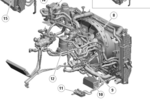
D4 Cooling System24 views
|
|

D4_Fuel_System25 views
|
|

D4_Fuel_System_Diagram_Decode22 views
|
|

D4 infotainment34 views
|
|

Thread upload6 viewsImage uploaded in thread 193079
|
|
TRIMLINE SYSTEMS what can i say.... 119 viewsThank you Gary from trimline
|
|

Hardware location of wiring audio information and entertainment system2214 viewsHardware location of wiring audio information and entertainment system2
|
|

Supplemental Restraint System - Description and Operation313 views
|
|

HVAC System Description and Operation9 views
|
|

Cooling System - Description and Operation 4.0L and 4.4L petrol engines 5 pages1028 viewsThis is a 5 page pdf that provides some insight into how the coolant flows thru all the hoses. Of interest is the paragraph,(page 3/5), that attempts to explain how and why the thermostat is designed to open at different engine operating temperatures - in brief, the reason for the spaghetti tangle of small hoses on the top of the engine.
There is also reference to an engine oil cooler that I gather cools something I think related to a supercharger, if fitted.
|
|

415-03 Audio System - Low and High Line Radios934 viewsThis 8 page pdf shows both the low and high line radios and their various components.
|
|

415-02 Antenna systems for AM/FM, Satellite, GPS and TV systems542 viewsThis is a 5 page pdf related to the antenna systems for the AM/FM radio, Satellite radio, the GPS/NAV and the optional TV.
|
|

419-08 Low and High line radio systems components and operation838 viewsThis 15 page pdf displays the radio components including pinouts for both the low and high line head units and the two Harman Kardon amplifiers including the Logic 7 amp. The steering wheel controls for both the radio and phone system are also outlined along with mention of the Sirius satellite radio feature.
|
|

Diesel - Ethanol co-fuel Paper114 viewsInteresting read - one local authority (Redland Shire Council) has 180 vehicles on trial and is pleased with the results; more power, engines run cooler; lower emissions including reduced smoke and it is a renewable resource to boot!
|
|

86 views
|
|

The Test Rig273 viewsDiscovery TDV6 SE - Adriatic Blue, Alpaca
Caravan - Future System Full Fibreglass (one piece) 21ft (6.10m)internal length
|
|

discovery 3 audio system49 views
|
|

Info cut and pasted from a tech document re the options for the video system322 views
|
|
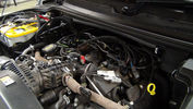
Dual Battery and ECU Chip175 viewsDual Barrery System by Traxide and Optima Yellow Top battey, Plus ECU Chip being fitted
|
|
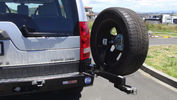
Kaymar Rear Bar Spare Carrier201 viewsOptional Spare tyre carrier for kaymar bar, more ground clearanve and a damned site easier to get the spare out once Dual Drawer System is put in.
|
|
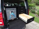
Drawers and fridge slide21 viewsDrawer system fitout
|
|
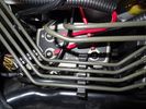
Ctek Smartpass11 viewsSmartpass used as second battery management system and isolator
|
|
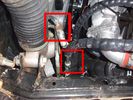
View of both hose connections to power steering system153 viewsBoth connections are shown. My friendly Qantas hydraulic hose expert cut off the elbow and modified it so I can re-install it to the PS rack before warranty work (and certainly before the vehicle is lifted off the body!!).
|
|
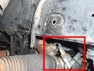
Further detail of attachment of the winch hoses to power steering system145 viewsThis is under the right (looking forward) lower plastic radiator cover.
|
|

Avic-F500BT164 viewsIntegrated Pioneer System with original Land rover Logo
|
|
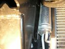
311 viewsLeft hand side impact absorber almost touching cooling system on NA spec truck. Absorber required modification.
|
|

400 viewsCloser view of leftside impact absorber. Note the thin piece of plastic I placed between the absorber and the cooling system component. Note air suspension hoses covered by protective tubing at bottom of photo.
|
|
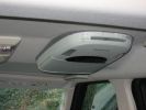
DVD System384 views
|
|

283 views
|
|

Thread upload3 viewsImage uploaded in thread 199339
|
|
Thread upload2 viewsImage uploaded in new thread
|
|
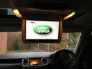
entertainment_screen24 views
|
|

Fuel Purge Valve and other hoses.846 viewsThis 6 page pdf shows the Fuel Purge Valve and associated hoses and describes how it is supposed to work. There are lots of good drawings of the fuel system. It is more complicated than one might think.
|
|
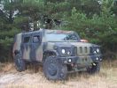
IVECO PANTHER £405 .000 with weapons system!!!!!121 views
|
|
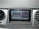
6" kogan system149 views
|
|
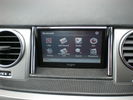
6" kogan gps/media/bluetooth system124 views
|
|
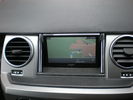
6" kogan system170 views
|
|
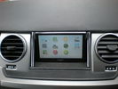
6" kogan system177 views
|
|

Four Wheel Drive System Info160 views
|
|

four wheel drive systems46 views
|
|

Fuel flap locking system missing bit21 views
|
|

handles locks latches and entry systems41 views
|
|
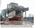
Messing with boats112 viewsShows our 300t capacity Lift System holding up an 80 tonnes module as the hull is winched underneath for final lowering and welding together.
|
|

Thread upload198 viewsImage uploaded in thread 162283
|
|
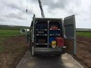
Transit van crew cab 6 drawer system11 views
|
|
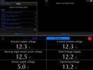
D4 system voltages19 views
|
|
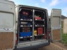
Transit van crew cab 6 drawer system14 views
|
|
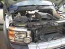
940 viewsFitting Second Battery and split Charge System
|
|
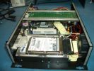
1225 viewsA view of the inside of the car PC, the laptop drive is the system drive and the large 400Gig drive is for storage.
|
|
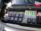
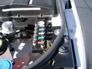
Picture of the engine compartment fuse panel5779 viewsEngine compartment fuse panel located near the battery. This is where F3E, (5 amp), F26E, (20 amp), Fuseable link 10E, (60 amp) and Relay 7E, the now upgraded 70 amp air compressor motor relay, part number YWB500220, (E is for Engine compartment fuse box), are all located. Fuse F35P, (5 amp), is inside the Passenger compartment behind the lower glove box door.
To keep the suspension from going down to the stops when driving, (or parked), it appears that it is only really necessary to remove F26E to depower the exhaust valve and generally keep all the valve block solenoid valves in a closed position trapping whatever air is within the air springs. F3E gets its power thru F26E, so when F26E is removed, the F3E circuit is automatically de-powered. F35P is more interesting in that battery power goes thru the ignition switch and F35P and then into the air suspension control unit. Apparently however, if F26E is removed, removing the F35P is not needed even when the engine is running.
With all fuses still in, if you have a problem, in practice, ideally, the compressor still works and will raise the 3 to an appropriate height. If so, one can then shut the engine off and allow the computers to go to sleep and then you remove the fuse(s). In actual practice, it seems that one need only pull the F26E fuse and can do so with the engine running. All the same, one might consider that the 3 is first a mobile computer, and secondly a 4x4. Computers prefer to go to sleep before the plug is pulled on them, however given that F26E circuit is always alive, then the computer never sleeps. With the fuse(s) pulled, and if you are still up, you can now be a 4x4 instead of a low rider. The whole purpose of the fuse pulling exercise is to depower the one and only system exhaust valve that is physically located within the compressor unit, (to keep it from opening), and secondarily to keep closed the four air spring solenoids within the block valves. This also shuts the air compressor down and stops the air compressor from making air even if the compressor is still good. That is why you initially need the fuse(s) in to allow the compressor to make air if it can.
|
|
Valve System487 views
|
|
Valve System Connections466 views
|
|
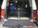
Frame for OL drawer system199 views
|
|
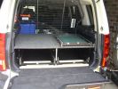
Opposite Lock Drawer system211 views
|
|
Complete system200 views
|
|
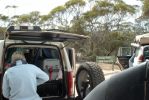
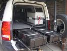
Southern end of Googs Track Sept 2007131 viewsOpposite Lock Rear Wheel Carrier, Opposite Lock Drawer System
|
|

533 viewsAdded an extra switch to the + leading to my PC and to the MP3 changer. As such I can cut off the power to both systems when needed. Learned that one after 2 days constantly working in the car, lighting the whole thing up during 2 days and noticed I couldn't start anymore :D. Saved by my wife's Freelander next to me :)
Also to be seen is the remote controller of the MP3-changer.
|
|
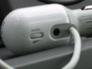
Close up...406 viewsSorry, this is blurry ! Oops...
This is a close up of the adapter itself... There is a 3,5mm input for the connection to the iPod. There is also a volume button. I don\'t use this because of interference between my quite old iPod and that system. But it does charge the iPod through the dock adapter.
|
|
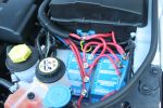
961 views'Rotronics' 3 stage battery management system installation
|
|

suspension 48 viewssuspension will raise when system cooled
|
|
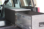
60 viewsORS (Off Road Systems)Sydney. Custom made cargo drawer
|
|
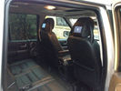
New Rear Seat Entertianment System newly installed15 views
|
|

VMS & HiICE integration81 viewsIntegration of VMS AVNC navigation system into D3 dash with HiICE stereo.
|
|
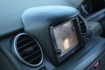
VMS & custom binnacle94 viewsVMS system and custom-made binnacle installed where LR factory satnav screen would be fitted.
|
|

T-Max split charge system41 views
|
|
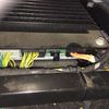
Harmon Kardon Audio Amplifier11 viewsLocated underneath right hand front seat. Connected to MOST system
|
|
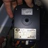
Nokia Bluetooth Module12 viewsLocated behind side panel of right hand luggage area. Connected to MOST system
|
|

D4 information and entertainment system120 views
|
|

information and entertainment system52 views
|
|
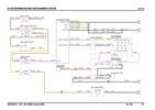
Thread upload8 viewsImage uploaded in new thread
|
|

Thread upload6 viewsImage uploaded in new thread
|
|

information and entertainment system (wiring diagram).pdf707 views
|
|

D3 infortainment system114 views
|
|

Thread upload4 viewsImage uploaded in thread 183698
|
|
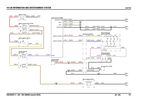
Thread upload7 viewsImage uploaded in new thread
|
|

285 views
|
|

Information and Entertainment System - wiring diagrams13 views
|
|

128 viewsWiring Diagram for HEVAC-System
|
|

6 views
|
|
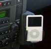
iPod cradle235 viewsThe dealer used the phone fitting and the iPod was installed via cinch connectors. Volume is controlled via the audio, charging function also included.
The sound even with the basic Audio system is terrific!!!
|
|
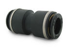
John Guest DOT all plastic fitting717 viewsThis is a picture of the John Guest DOT all plastic union. If you look closely, you can see the DOT imprinted in raised letters on the end of the fitting. This is of a 1/4" connector rather than the 6mm that the 3 requires.
The picture is similar to the air suspension pneumatic fitting union that Land Rover sells as replacement part # STC8580. This is for 6mm OD tubing size. The STC8580 comes with what are called "Collets" at each end that cover up the press to release feature underneath. See the John Guest web site www.johnguest.com under the Pneumatics section and also in Downloads for their catalog for install and remove instructions.
The actual "air brake spec" fitting that Land Rover provides has an interior 4mm OD ferrule that slips inside the 4mm ID of the nominal 6mm tubing. I have not yet been able to obtain the John Guest part number for the LR fitting, only the LR part number. This part number was generated for the RR Classic air systems.
|
|

L319_Discovery_4_SDV6_3L_Diesel_EU5_OBD_Engine_Management_System28 viewsL319_Discovery_4_SDV6_3L_Diesel_EU5_OBD_Engine_Management_System
|
|

LA415-001 - Technical Bulletin - Accessories DVD System Audio Fault68 views
|
|

LA415-003 - Technical Bulletin - Infotainment System Diagnosis82 views
|
|

LA501-020 - Technical Bulletin - Supplemental Restraint System Overlay Harnesses60 views
|
|

Air Suspension System Parts, Layout, and Operation7062 viewsThis 22 page pdf gives a pretty good description of how the system is supposed to work, plus shows the various parts and the electrical including fuses and relays etc. Of the files here, this is the most useful.
As with all the pdf's here, you can download and print it out.
|
|

LED trailer lights adapter for LR3843 viewsThis doc includes a partial list of materials and the instructions/links required to construct an adapter to prevent LED trailer lights from pulsing due to the 3's diagnostic circuits interrogating the signal light circuit.
Using the adapter also facilitates the green flashing of the dash located trailer indicator when the signal lights operate plus inhibits operation of various systems such as the backup sensors, etc.
|
|

File - Load Retention System - VUB503130.pdf246 viewsPDF extracted from Premier Automotive Group (T/AS Land Rover Australia) publication number L3879.
|
|

wiring audio information and entertainment system1179 viewswiring audio information and entertainment system1
|
|

wiring audio information and entertainment system170 viewswiring audio information and entertainment system
|
|

Locking system - Evqoue76 views
|
|
Thread upload28 viewsImage uploaded in new thread
|
|
Block Diagram of Disco 3 / LR3 Air Suspension System.1552 views
|
|

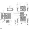
Air System Schematic with parts identified.1374 viewsAir system block diagram with components numbered and identified.
|
|
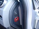
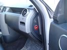
Air Suspension ECU Fuse 35P cut off switch.3820 viewsThis shows the SPST rocker switch mounted in the blank plate installed in lieu of a manual passenger side air bag shut down switch - now automatic via passenger seat pressure switch. Fuse 35P (5 amps) is located in the interior fuse box behind the lower glove box and protects the ignition power supply to the Air Suspension ECU. When the SPST switch is moved to the OFF position, the RAISE /LOWER switch on the centre console is not powered, and hence does not function. As such, some signals from the wheel height sensors and CPU are ignored. By itself however, removing F35P will probably not stop the 3 from self dropping, particularly after the engine is turned off.
Fuse F3E, (5 amps), located in the engine bay fuse box by the starting battery protects the circuit that provides feedback to the Air System ECU indicating that the Compressor Relay has successfully operated and that the Air Compressor is or should be operational, can also be removed, (but is probably not totally necessary), as it gets its power thru F26E. Hence Fuse F26E, (20 amp), also located in the engine compartment fuse box is the fuse that must be removed. This fuse protects the circuit that provides full time battery power to the Air System ECU. When in place, current thru the fuse powers the periodic re-levelling action, (usually lowering a bit with that brief air release noise), that often occurs when the vehicle is parked and the engine is off.
Removing F26E fuse will stop the auto levelling action and also inhibit any other down to the stops signals, (engine running or not). When F26E is removed, no power can flow thru to F3E, hence removing F3E is more for insurance than an absolute requirement. The same with F35P, removing F26E removes primary full time power from the Air Suspension ECU, and hence removing the F35P fuse should not really be required either as long as F26E has been removed.
|
|
Air Suspension ECU Fuse 35P Shut Off Switch2635 viewsA more distant view of the shut off rocker switch in the ON position which is the normal position for when all is working as Land Rover intended.
Ideally, (but not totally necessary), the F35P circuit should be powered or de-energized after the various computers have gone to "sleep".
Similarly, removal of the F26E or F3E fuses is preferable after the computers have all gone to sleep but it appears that no real damage will be done if the fuses are removed while the system is energized. Pulling F26E is the main full time fuse that powers the air suspension computer. As such, once F26E is removed, pulling F3E is not really required.
Power for the compressor goes thru the 60 amp fusible link and relay, however control of the relay is via the air suspension computer so depowering the air suspension computer effectively depowers the air compressor and the internal exhaust valve relay/port.
|
|
View from front left side looking towards rear aux battery compartment under cover 646 viewsAs there is no Fuel Burning Heater in the NAS V8 petrol vehicles, there is space available to install the FASKIT panel here. The piping is such that each air spring can be isolated from the air system and then filled one at a time manually via the Schrader valve. There are five Schrader valves and five shutoff valves. The fifth valve nearest the gauge controls air from the compressor, and can provide fill up air via a jumper fill line assuming the compressor is still operational.
|
|

NAS 7 Pin Round Socket + 4 Pin Flat Socket oriented as installed.752 viewsThis is the layout you see when you look into the NAS Land Rover sockets as installed at the rear of the LR3/4. The flat 4 pin socket is located under the round socket.
Wiring order is relative to the slot on the round socket, and hence the same as the other jpg where the slot is shown at the top.
The CJB monitors the front and rear turn signal lamps and can detect if more than four lamps are fitted, (the side turn signal lamps are not monitored). This is another reason for using genuine LR bulbs as off shore bulbs can have varied and out of spec resistance values.
When a trailer is detected, the trailer warning indicator in the instrument cluster is supposed to flash green in synchronization with the turn signal indicators.
If one or more of the turn signal lamps on the vehicle or the trailer are defective, the trailer warning indicator will cease to flash any longer. This is to alert the driver to probably bulb failure.
If the trailer has LED lamps installed, and no LED adapter circuitry is used, most likely the trailer will not be sensed and systems such as the backup sensors will not be disabled.
|
|

Underhood Fuse and Relay Box drawing 3054 viewsShows the various fuse and relay locations. Fuse 3E, (5 amp), and Fuse 26E, (20 amp), as well as upgraded 70 amp Relay 7, part number YWB500220, locations are displayed. Relay 7 sends battery power to the compressor from the 60 amp fusible link called up as 10E. Fuse 26E is what provides full time always on battery power to the air suspension ECU and hence powers the auto level wakeup when the vehicle is shut down and say parked for the night. Removing F26E is the primary method to disable the air suspension system; Removing F35P is more if you want to experiment with it from inside.
I found it useful when I had a suspension problem, (actually a wheel alignment problem picked up by the steering wheel angle sensor), that only showed itself on the highway but allowed for no trouble light driving in the city. This was because in the city, the steering wheel was always in motion and rarely was the vehicle driven in a near straight line for very much distance.
|
|

solo steep gravel stop = park brake plus reverse on shifter333 viewsso our disco II\'s locked all 4 wheels with brake but now the modern lr3 slides away with only the park brake!!!! 1. put auto shifter in reverse (low gear) with foot on brake, 2. apply park brake, 3. get out and snap photo incase something fails and it slides away ;)
I reversed up the hill from this position, system decided to engage extended heigh mode for some reason trying to gain traction on loose surface.
|
|

Air Suspension Wiring Sheets3037 viewsThese two sheets show the wiring and fuses related to the operation of the air suspension system. Fuses F3E, F26E, and F35P are shown as well as the interior up down switch and the wheel height sensors.
As with all pdf's, you can rotate them to view plus download and or print out as you wish.
|
|

LR3 Brake Wear Sensor Wiring1517 viewsThis 1 page wiring diagram pdf shows that both the front and rear brake pad wear sensors are part of a closed series circuit to ground.
In operation, when all is good, the series circuit is grounded and the amber brake wear warning indicator on the instrument panel is not illuminated.
When the pads on one wheel, either the left front, or right rear, become too worn, the respective sensor is "cut" which results in an open circuit condition. This causes the dash brake wear indicator to illuminate.
The circuit is like the old style Christmas light strings where one burned out bulb caused the whole string to go out.
A quick field fix to get the dash light to extinguish in lieu of replacing the sensor and pads etc is to disconnect the brake pad wear sensor and short across the two open conductors of the vehicle side connector plug. This of course means you now have a normal vehicle, one of the thousands that do not feature brake pad wear information systems.
|
|

Fuel Tank Internals, Description and Operation 809 viewsThis 10 page pdf shows views of the fuel tank internals, what the various pieces do and describes how the fuel storage system is supposed to operate.
As usual, you can download it, save, and print as required.
|
|

SDARS Satellite radio operating instructions 352 viewsThis is a 14 page pdf portion from the Owners Handbook with regard to operation of the satellite radio system operating on the Sirius channels.
|
|

Stop Light Lamp Circuit pdf2491 viewsThis pdf shows the brake light circuit for the NAS LR3.
Note that power for the brake light bulbs can come either thru the brake light switch power feed /contacts plus also from the Hill Decent Control, (HDC), system relay located within the Central Junction Box, (CJB) - yes two separate sources of power for the brake light bulbs. This would tend to explain how a brake light circuit concern shows up as a hill decent fault message; also why lesser vehicles without hill decent braking mechanisms, (HDC), never display this sort problem when a brake light bulb or switch acts up. You never have a problem related to a system that does not exist.
Additional evidence of the relationship of the HDC and the tail light circuit is demonstrated by when the HDC actually acts to slow the 3 down, the brake lights automatically illuminate even if the slowing action was merely retarding the engine speed or shifting to a lower gear, (in other words, no foot on the brake pedal).
There is also a tie in to the Cruise Control and hence a failing brake light switch can affect cruise operation or just create false Cruise Control messages. To further complicate the issue, while there are no messages generated, operation of the radiator electro viscous fan can also be negatively affected by the fouled set of secondary contacts within the brake light switch. This is all because the NC contacts within the brake switch send misleading messages to the ECU.
While the ground wire design is similar to other vehicles, note the grounds for the brake light filament and the reverse light filament are common on each side. That means that if one has a non functioning brake light on one side, the reverse light may not also work or that some problem with the reverse lights could back feed into the brake lights. This situation while unusual, can result when grounds are corroded probably due to swimming in rivers and creeks or just routine driving in a marine environment.
|
|

LTB00008 - Technical Bulletin - Audio System Amplifier Diagnostic Aid75 views
|
|

LTB00063 - Technical Bulletin - Accessory (Rosen System) DVD Diagnostics60 views
|
|

LTB00109 - Technical Bulletin - Cooling System Pressure Test66 views
|
|

LTB00179 - Technical Bulletin - Infotainment System Lock-up - Repair Procedure79 views
|
|

LTB00180 - Technical Bulletin - Supplemental Restraint System Power Circuit Discharge59 views
|
|

LTB00269 - Technical Bulletin - Air Suspension System - Compressor Delivery Valve and Drier Replacement Software Update2926 views
|
|

LTB00270 - Technical Bulletin - Suspension System Software Update When Replacing Compressor221 views
|
|

LTB00310 - Technical Bulletin - Air Suspension System - New Height Sensor Availability144 views
|
|
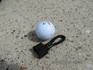
MOST fiber optic loop tool468 viewsThe looping tool in the jpg uses the Land Rover type plastic fiber optic cable with both ends feeding back into a female fiber optic connector that mates with the male fiber optic connectors on the Land Rover system.
The purpose of the loop is to allow one to disconnect MOST connected items such the BlueTooth module or the HK amplifier but allow the MOST system to still transmit signal from the head unit as the circuit would remain closed and hence complete. Of course with the Bluetooth module disconnected, there would be no Bluetooth available, however the radio and NAV would still function.
The looping tool allows one to troubleshoot the system by removing one component at at time from the MOST loop. In other words, what might appear to be a radio problem could be a Bluetooth problem - that sort of thing.
|
|
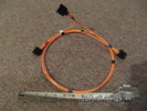
Fibre Optic MOST cable between components.560 viewsThis is a typical section of Plastic Optical Fiber (POF) optic cable with the orange coloured cladding covering the perimeter of the light transparent core. This is used as the MOST (Media Oriented Systems Transport) data transmission medium.
Note that each MOST 1355426 optical connector holds a pair of light conductor cables, one transmitting optical signal in, and the second, optical signal out. When connected to the other cables and devices, the cables form a continuous loop.
The light signal within the cable is red colour as one might expect. One break or disconnect anywhere along the loop shuts down signal transmission to all the connected components.
|
|
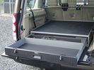
TL1 Secure Storage Systems64 views
|
|

90 tonnes Transformer - Tooley Street84 viewsOur 300t Lift System with a 90 tonnes transformer hanging from it just before lowering 9 metres into a basement.
|
|
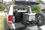
277 viewsStorage System
|
|
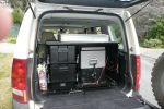
317 viewsStorage System
|
|
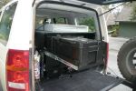
256 viewsStorage System
|
|
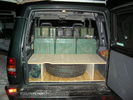
Load system55 views
|
|
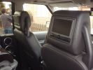
TFC RSE system417 views
|
|
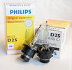
Philips D2S 85122 C1 Xenon 4300K projector HID bulb962 viewsThis is the 4300K OEM bulb in our HID Xenon projector headlights. People who design illumination systems regard the 4300K colour as a good compromise to provide what is called definition. This is effectively the ability to actually determine what an object being illuminated probably is. The more blue colour bulbs, say 5000K and greater, result in a reduction in the ability to distinguish detail, (regardless of brightness), of the object being illuminated. Effectively, you can see the object but you cannot quite figure out what it is. This is because the more blue frequencies means there are fewer other frequencies of light that allow our eyes to actually discern what an object really is.
The 4300K colour temperature applies to clear air conditions; for rain, dust, snow, fog, etc, then a yellow 2500K colour temperature is preferable. 2500K provides more contrast and there is less back splash of light off the air particles. In blowing snow, this means less sparkle back. Flat top cut off of the light beam, (which is the pattern our projector lights have), is important to reducing back splash - hence you do do not want roof mounted lighting for adverse conditions - as low down as possible is preferable, (which is why fog lights generally sit low.)
|
|
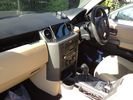
NEW sound system mod33 views
|
|
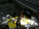
dual batery system114 views
|
|
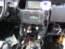
257 viewsSystem testing. Nothing caught fire, which is a success in my book! Just know that the rover gets very angry when all of those control panels are disconnected.
|
|

Pollen Filter Replacement in HVAC System506 viewsThe attached single page doc includes links to pictures of the procedure to replace the "air" filter behind the passenger side glove box related to the Heater AC system.
Part numbers are provided for both Land Rover and Mann filters, both the activated carbon type and the non charcoal filters.
|
|

Complete underbody protection system photo render172 views
|
|

Complete underbody protection system117 views
|
|
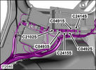
Audio amplifier & DAB unit & Door lock system106 views
|
|

service action Q179 surround camera BSOD225 views
|
|
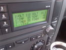
Voltage Display Page Radio Head Unit 118 14.2840 viewsThis shows the voltage/temperature/timer display page within the 6CD-465 radio head. There is a second file within this album, a doc file, that outlines the procedure to access the diagnostics.
The 14.1 volts number was the approximate vehicle system voltage with the engine running; the 118 number infers 11.8 volts which is the low power infotainment system shutdown cutoff voltage. The factory default setting is 135 or about 13.5 volts. By holding the keypad 1 button down, the 3 digit volts numbers will decrease 001 at a time until the keypad 1 button is released. Decreasing the number from 135 to some lower number should increase the time the system will remain on with the engine off.
The TEMP numbers refer to Fuel Burning Heater, (FBH), temperature values. 85 is apparently a high limit and 46 was the number when the jpg was taken. This number varies and given that there is no diesel fueled FBH in our NAS petrol engine vehicles, what the value refers to is unclear. The TIMER numbers also relate to the diesel fuel burning engine heater and perhaps make more sense being 00.
|
|

Radio Head 6CD-465 Display diagnostics and low power procedure757 viewsThe one page doc outlines the procedure to access the diagnostics for the 6CD-465 entertainment system in most of our LR3's.
|
|

Rosen Owners Manual893 viewsThis 28 page Owners Manual is the Rosen version written specifically for the A10 model DVD Video Game Entertainment System player that may in attached to the roof of your 3.
Discussed is how to use the remote control, the wireless headphones, the TV feature if installed, and how to change from 16:9 widescreen format back to the older 4:3 format.
|
|

RRS Air Vent System45 views
|
|
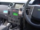
Two sat nav systems - LR & SmartNav424 views
|
|

Thread upload1 viewsImage uploaded in thread 200210
|
|

Thread upload1 viewsImage uploaded in thread 200210
|
|
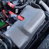
Thread upload4 viewsImage uploaded in thread 200210
|
|

Siemens VDO Piezo Common Rail injection PCR 2.314 viewsDetailed information about te sort of injection system in the Disco 3
|
|

My old Seadoo RXT 291 viewsOn holiday with the ski's, St Tropez France.
My RXT on the left, supercharged & intercooled 1500cc rotax engine...aftermarket freeflow intake system by RIVA, SOLAS blueprinted prop, race sponsons, RIVA intake grate & opas system removed for less drag...estimated 230hp.
Proven 70mph (with GPS & Radar gun)
On the right is my best man's GTX Ltd. with 185hp and good for 60mph with a tail wind...
|
|

Glen Strathfarrar in front of a Hydro System Waterspout 3444 views
|
|
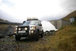
Glen Strathfarrar in front of a Hydro System Waterspout 2425 views
|
|

2010 Calendar Entry460 viewsGlen Strathfarrar in front of a Hydro System Waterspout 1
|
|
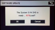
Software Update SYSTEM96 views
|
|

Thread upload13 viewsImage uploaded in thread 158628
|
|

starting system59 views
|
|
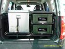
160 viewsG4 storage system
|
|

Thread upload6 viewsImage uploaded in thread 194599
|
|

68 views
|
|

Thread upload5 viewsImage uploaded in thread 118479
|
|
20 views
|
|

From "LR Onelife" Magazine- Best Terrain Response system description Ive seen492 views
|
|

Roof Rack pulley system17 views
|
|

Roof Rack pulley system16 views
|
|

Roof Rack pulley system17 views
|
|
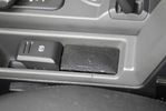
Little speaker to get nav instructions while listening to the radio131 viewsThe sound of the PDA is routed to the Aux input of the car. this way MP3 music and Nav instructions get to the car\'s audio system. But when you want to listen to the radio and also hear nav instructions, you can\'t hear them both through the car radio. For that I mounted a little speaker.
|
|

restraint system, components229 views
|
|

TPMS System18 views
|
|
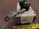
Radio Noise Filter Transmission Electronic Control Unit913 viewsThe jpg shows part number LR020488, a noise suppression capacitor located underneath on a bracket on the right side of the transmission forward of the selector shaft lever. The suppressor is connected to the transmission wiring harness and prevents solenoid operating noise affecting the audio system.
Failure of the capacitor is most often discovered as a result of either black smoke from below and or the blowing of 10 amp fuse F30E located in the engine compartment fuse box. This fuse protects the power circuit to the Transmission Engine Control Unit. When the fuse blows, the engine will still run however you have no gears, hence movement of the 3 is inhibited.
Anything over eight years in service is considered good capacitor life. If the capacitor does fail and fuse 30 blows, a quick fix is just to disconnect the capacitor and replace the fuse.
The capacitor might be missed by the DOT/FCC but the 3 does not seem to mind. With the filter disconnected, solenoid noise might be heard on some radio stations but at least the 3 would be in motion.
|
|

Suspension system fault codes and diagnostics32 views
|
|
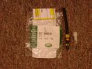
Voss System 203 connector 6 mm for valve blocks 905 viewsThis is Land Rover part number RQC000030, the Voss fitting for the axle valve blocks. I think it is a Voss System 203 6mm fitting, Voss part number 5 2 03 11 01 00.
The parts bag comes with the white plug inserted in the brass threaded bit with what is called the brass cutting ring placed on the tip of the white plastic plug. The idea is that one screws, (M10 x 1 thread), the brass insert into the appropriate hole with the white plug still in the brass insert. Once the brass is tight, (12 mm wrench), then the white plug is pulled from the assembly leaving the cutting ring down inside and under. One then pushes in the 6 mm tube end about 20 mm or so and the tube slides down thru the brass cutting ring, (2 internal sloped one way cutting ridges). When the tube is in far enough, one pulls upwards a bit and the ring cuts into the plastic such that the tube will not pull out. To remove tube, one unscrews the brass nut and all comes out, sort of like I have shown with the short piece of 6mm tubing. The white plug is a throwaway item upon install of the tubing.
|
|

Voss B203 Fitting Install957 viewsNote on the first page, the reference to DIN 73378 and D74324 and also PA11 and PA12 material when referencing suitable spec nylon (polyamide) air line for motor vehicles. I think some of the 6mm fittings used on the 3 for the valve blocks are the System 203 type and called up as Land Rover part number RQC 000030. The Voss part number is I believe 5 2 03 11 01 00.
|
|

Voss System 203 Connector cut thru, (similar to in valve block).677 viewsThis is a cut thru of a Voss System 203 connector. The top third of it is similar to the connector that holds the three 6mm plastic tubing lines into each of the front and rear valve blocks.
I say top third, as per the other pictures, the 3 has a Voss assembly that threads into the plastic of the valve block, whereas in the cut thru above, the Voss brass assembly is threading into the brass body of a metric threaded adapter for threading into a standard type metric threaded hole. Note also the two one way sloping ridges of the cutting ring, and the two interal O ring seals that mate with the plastic tubing. There is additionally the small squashed O ring to provide a seal related to the external thread of the Voss cutting ring assembly; (similar to the larger O ring for the brass body external thread).
|
|

Thread upload4 viewsImage uploaded in thread 142922
|
|
Amdeal 30ft / 10M USB Digital Microscope Cable Wire Endoscope Camera Video Recording Inspection Pipe Camera - Waterproof, 4 LED Lights27 viewsUnder XP system, can watch video directly without install software. By using our software, can take photo,record video, and save the video in the PC. Such USB microscope widely used to inspect tube, check the body, magnify stamps, coins, antiques, insects, electric circuits, machines, fabrics, food, decorations, etc. Please notice that the wire camera is designed for industrial use, not for medical use.
Camera: 1/6" VGA COMS
Pixel: VGA 300K
Resolution: 640x480,352X288,320X240,176X144,160X120
Capture Resolu
|
|
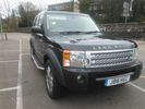
1st Disco18 viewsI fell in love but she broke my heart with her unloved braking system and generally being not cared for by her previous!!!
|
|

1st Disco13 viewsI fell in love but she broke my heart with her unloved braking system and generally being not cared for by her previous!!!
|
|
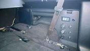
PS2 + Split charge system 10 viewsPS2 - Wireless controllers and headphones.
Split charge system with auxiliary sockets with digital voltage display
|
|
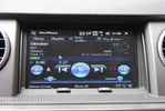
MP3 player to play music on the car system127 viewsUsing an app called mortplayer on the PDA to play mp3 files on the car's ICE system.
It has a nice interface meant for in-car use
|
|
|
|