| Search results - "Springs" |
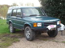
51 viewsD44 front winch bumper. Ali washer bottle. D44 rear h/d bumper. centre diff lock. 235x85x16 pirelli muds. OME +2" springs & shocks. front diff guard. side tree bars. wired for roof CB. Aux fuse block. safari snorkel. extended wading tubes. the list goes on...
|
|

10 Cracked smoking parking brake drum338 viewsNote the crack in the face of the brake. This showed mangled parking brake springs and other bits. Also a bit of melted rubber was drooling out of the crack. Started to remove the brake caliper and enjoying the flies in 45 deg C heat. Ah, the wonderful Aussie climate in January.
|
|
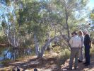
Windich Springs, People not in our group221 views
|
|
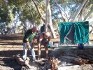
Cooking Roast at Pierre Springs225 views
|
|
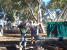
The roast is ging well, Pierre Springs206 views
|
|
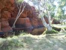
Durba Springs206 views
|
|

Durba Springs202 views
|
|
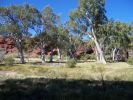
Durba Springs198 views
|
|

Durba Springs192 views
|
|
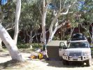
Campsite, Durba Springs222 views
|
|

Sunrise Durba Springs185 views
|
|
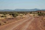
Owen Springs - Towards the West MacDonnell Ranges161 views
|
|
Cruising North of Alice Springs236 views
|
|
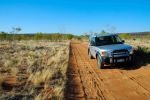
Corrugations on the Owen Springs track219 views
|
|
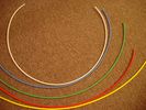
6mm Heat Shrink colours 362 viewsI decided to colour code the tubing so I used 6mm electrical heat shrink.
As there is no apparent colour coding re the 3, I tried to emulate the P38 coding; #1 LR red, #2 RR blue, #3 LF yellow, and #4 RF green. This was not doable as both left side air springs have green coloured tubing coming off the top of the front and rear air springs. I therefore arbitrarily chose the Left Rear to be red; Left Front green; Right Front yellow; Right Rear blue; and for the air compressor supply line, White coloured heat shrink. Since two new lines tie into each air spring line, I made the line between the air spring and the FASKIT, a single solid colour, and the line from the FASKIT to the valve block, White, plus the related appropriate solid colour.
|
|
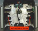
airbag latch hooks342 viewsAirbag retained to steering wheel by 2 latch springs located onto latch hooks of steering wheel
|
|
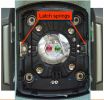
airbag latch springs326 viewsAirbag retained to steering wheel by 2 latch springs located onto latch hooks of steering wheel
|
|
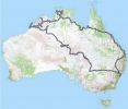
Our Trip Apr-Aug 2008135 viewsGosford to: Broken Hill, Innamincka, Birdsville, Alice Springs, Bungle Bungle NP, Broome, Gibb River Rd to Mitchell Falls and then Kunnunurra, Darwin (for tail gate Repair), Normanton (via Roper Bar, Borroloola, Lawn Hill, Burketown), Townsville, down coast to Noosa then inland to home. TRACK TRACE BY TRACKRANGER SOFTWARE ON ASUS UMPC.
|
|
214 views
|
|
200 views
|
|
198 views
|
|
196 views
|
|
184 views
|
|
141 views
|
|

Mvubu in Botswana 2014119 viewsMvubu 2014 Discovery 4 TDV6 XS, Corris Grey.Snorkel, OL Bull Bar, Winch,OME Heavy Duty Coil Springs,Light Guards,17" Black Wheels,Cooper ST max,Dual Battery+Inverter,Drawer Storage,FR Rear Ladder,Hannibal Roof Rack,80L Excel Long Range Fuel Tank,HiLift Jack Points,75L Water Tank.
|
|
old springs 21 views
|
|
Thread upload17 viewsImage uploaded in thread 151102
|
|
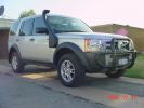
King Springs Lift331 viewsSpring Lift and Safari snorkel fitted
|
|
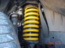
King Springs Lift240 viewsFront Spring
|
|
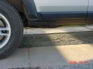
King Springs Lift217 viewsRear underbody Clearance
|
|
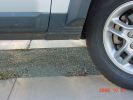
King Springs Lift205 viewsFront underbody clearance
|
|
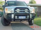
215 views
|
|
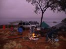
Bush camp 70km South of Alice Springs114 views
|
|
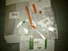
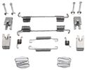
EPB kit spare springs37 views
|
|
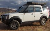
Widow maker - Alice Springs116 viewsHyper extended - Climbed the widow maker and the suspension found its way to this position by the top without any intervention.
|
|
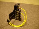
FASKIT on end view 864 viewsEnd and rear view of the FASKIT. Yellow lines are as shipped for hooking to the air supply; one line to valve/filler and other is to gauge. I will modify the arrangement to delete one of the yellow lines such that gauge line plugs into where the second yellow line is right now,(will be only one yellow tube), and then the air source line will plug into the port controlled by the valve, (hidden in this view but visible in other view). When white valve is in the ON position, gauge will read air source pressure, and be available to supply air to any of the selected four air springs. When valve is closed, the gauge will show individual air pressure in each of the air springs when a jumper is run between the gauge Schrader valve and the appropriate air spring Schrader valve.
|
|
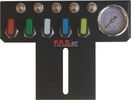
FASKIT air panel unmounted842 viewsThis is the manual air valve panel that is mounted in the "empty" space where the FBH normally resides. The gauge reads to a maximum of 25 Bar. The air tank relief valve is set just over 16.5 Bar (240 psig); the front air springs run maybe 9 Bar, (130 psig) and the rear, somewhat less, perhaps between 5 and 8 Bar. (70 to 115 psig). Max theoretical air spring pressure at full compression due to a big bump and full gross is approximately 27 Bar (390 psig).
|
|
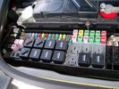
Picture of the engine compartment fuse panel5779 viewsEngine compartment fuse panel located near the battery. This is where F3E, (5 amp), F26E, (20 amp), Fuseable link 10E, (60 amp) and Relay 7E, the now upgraded 70 amp air compressor motor relay, part number YWB500220, (E is for Engine compartment fuse box), are all located. Fuse F35P, (5 amp), is inside the Passenger compartment behind the lower glove box door.
To keep the suspension from going down to the stops when driving, (or parked), it appears that it is only really necessary to remove F26E to depower the exhaust valve and generally keep all the valve block solenoid valves in a closed position trapping whatever air is within the air springs. F3E gets its power thru F26E, so when F26E is removed, the F3E circuit is automatically de-powered. F35P is more interesting in that battery power goes thru the ignition switch and F35P and then into the air suspension control unit. Apparently however, if F26E is removed, removing the F35P is not needed even when the engine is running.
With all fuses still in, if you have a problem, in practice, ideally, the compressor still works and will raise the 3 to an appropriate height. If so, one can then shut the engine off and allow the computers to go to sleep and then you remove the fuse(s). In actual practice, it seems that one need only pull the F26E fuse and can do so with the engine running. All the same, one might consider that the 3 is first a mobile computer, and secondly a 4x4. Computers prefer to go to sleep before the plug is pulled on them, however given that F26E circuit is always alive, then the computer never sleeps. With the fuse(s) pulled, and if you are still up, you can now be a 4x4 instead of a low rider. The whole purpose of the fuse pulling exercise is to depower the one and only system exhaust valve that is physically located within the compressor unit, (to keep it from opening), and secondarily to keep closed the four air spring solenoids within the block valves. This also shuts the air compressor down and stops the air compressor from making air even if the compressor is still good. That is why you initially need the fuse(s) in to allow the compressor to make air if it can.
|
|
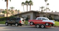
Towing my 56 Chevy264 viewsI towed my Classic Chevy about 650 miles from Palm Springs to Reno, including over the Sierra Nevada mountain pass (7,085 feet (2160 meters)) and the LR3 pulled very well.
|
|

New toys - 2" lift Lovells Gas Legend - (+100kg springs)51 views
|
|
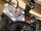
Compressor Electrical Plugs 1406 viewsThis shows the two electrical connectors; the two pronger is the power to the compressor, and the multi-pin connector carries control signals. Also the temporary red plug is where the 6 mm tubing from the centre valve block connects. This line carries both the compressor and exhaust air to and from the springs.
|
|
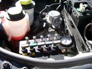
View of mounted panel from front left side877 viewsNote that all valve handles are shown in the OFF position, (the trouble position). In this case, the air that is in the air springs, (if any), is trapped in there - that is the valve blocks cannot vent whatever air is already in the air springs as the air lines between the springs and respective valve blocks are closed off by the FASKIT valves. In operation, there may be only trouble with one air spring, (perhaps a wheel height sensor), and as such, only one valve would need to be closed. If there was complete air compressor failure, then all valves would be closed and then as required, each spring could be manually filled from an outside clean dry oil free air source.
|
|
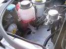
Empty space in NAS LR3 for location of FASKIT panel599 viewsThe empty space is available as the North America Spec gasoline engine LR3's do not have the Fuel Burning Heater installed. The air lines from the four air springs and the air tank will appear to rise up from under the headlight assembly. The lines to the front block valve assembly located behind the front right fog light will sort of run within the bumper across the front of the radiator down into behind the righthand fog light. The rear lines somewhat follow the path of the existing air feed line from the front valve assembly to compressor. Rather than be located between the left front fender liner and left metal wing however, the four lines will feed thru the empty wing space inside and above the wheel well arch and exit down by the left front mud flap. From there, the lines run along the left frame member above the air tank and then parallel the frame over top the compressor to the top of the rear left air spring where the rear air block valve assembly is located.
|
|
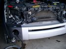
Wiring, (tubing), loom exiting temporarily from the front right fog light.569 viewsThe front axle air valve block is located just behind and below the fog light. Access to the valve block is by removing the right front fender liner, (or the bumper). The FASKIT lines are attached to the left and right front air spring lines at this location; also compressor air is taken from this location as well. Cutting the lines at as few different locations makes it easier to find leaks at a later date. As above, five 6mm air lines run from the FASKIT panel to the front axle air valve assembly and run within the loom. Two pair of the lines are for control of the air springs, and the fifth line taps the air supply at the valve block assembly off the compressor. This will be the air source line rather than tapping in directly to the high pressure air tank.
|
|

Front replacement coil spring - King Springs127 views
|
|

Rear replacement coil spring - King Springs116 views
|
|
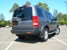
After replacement heavy duty coil springs fitted129 viewsReplacement King Spring coils fitted 22 February 2008. Oem shocks retained.
Wheel arch measurements (note that the old springs - weighing perhaps 30kg - were sitting in the boot when the "after" measurements were taken):-
FRONT
Before - 33" (84cm)
After - 35¼" (89.5cm)
REAR
Before - 33" (84cm)
After - 34¼" (86.7cm)
|
|
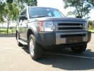
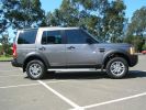
After replacement heavy duty coil springs fitted188 viewsReplacement King Spring coils fitted 22 February 2008. Oem shocks retained.
Wheel arch measurements (note that the old springs - weighing perhaps 30kg - were sitting in the boot when the "after" measurements were taken):-
FRONT
Before - 33" (84cm)
After - 35¼" (89.5cm)
REAR
Before - 33" (84cm)
After - 34¼" (86.7cm)
|
|

From wheel arch after replacement heavy duty coil springs fitted135 viewsAfter replacement heavy duty coil King Spring coils fitted 22 February 2008. Oem shocks retained.
Wheel arch measurements
FRONT
Before - 33" (84cm)
After - 35¼" (89.5cm)
|
|

Rear wheel arch measurement after replacement heavy duty coil springs fitted146 viewsAfter replacement heavy duty King Spring coils fitted 22 February 2008. Oem shocks retained.
Wheel arch measurements (note that the old springs - weighing perhaps 30kg - were sitting in the boot when the "after" measurements were taken):-
REAR
Before - 33" (84cm)
After - 34¼" (86.7cm)
|
|

Stanley Chasm - Alice Springs244 views
|
|
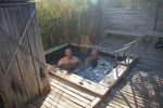
Early morning dip in hot springs82 views
|
|

101 viewsDown in the river bottom there were a bunch of temporary run-off springs. These will be gone in a day or two.
|
|
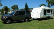
Towing outfit201 viewsTowing our Trailcraft 5.4m "Panorama Dirt Road" caravan (March 2008).
Heavy duty springs and 150mm hitch riser on LR "plough" has made the outfit level. There's a slight nose-up attitude and some pitching front and back whilst under-way. We're looking forward to taking delivery of a Mitchell Bros towbar so that we can use our Hayman Reece weight distribution hitch (which will correct the nose-up and reduce the front-back pitch).
|
|

111 views
|
|
|
|