| Search results - "Sign" |
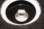
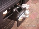
180 viewsThe offending adapter in the D4 courtesy of the bright young designers, who modified it from the perfectly acceptable hex nut
|
|
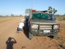
08 D3 stranded with a seized smoking wheel315 viewsAbout 1 hr after replacing the blown tyre, strange noises emanated from the stability control system and speed dropped off. Then I looked in the rear view mirror, and noted a cloud of dust along with a whiff of black smoke. This led to a very quick stop (no traffic on this route for over a week, so no worries about having to signal exiting the road). Took a look and WOW. The right rear wheel was glowing a dull red colour, and burning rubber smoke was wafting from the red glow over the fuel lines.
|
|
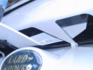
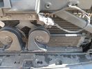
Antenna Mount462 viewsBracket mounted using existing holes behind the grill. The design of this bracket is listed elsewhere.
|
|

15 First sign of bits of parking brake failure336 viewsNote the complete lack of pad from the parking brake. Not only was there no composite brake material left, but the drum was somewhat twisted and connecting bits all smashed. Also a small drip of melted rubber from wheel bearing parts....
|
|
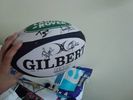
13 viewsGot it signed by the SA team ;-)
|
|
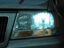
Standard hid bulb - light everywhere and glare caused by light in bottom of bowl95 viewsWhilst the beam pattern is ok the problm is that with 300% more light the spillage into the bottom of the reflector bowl is seen as glare by other motorists. it also is the reason the overhead motorway signs are lit up so well be bad retrofit xenons
|
|
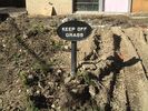
Irony325 viewsSelf Explanatory, there is no grass.
|
|

FBH_App-CheckSignal_Screen19 views
|
|

Terratrip 202 V4 possible discrete location140 viewsAttached to ashtray - allowing removal / unplugging when not in use by pulling out the ashtray.
Terratrip is an odometer for use in rallies / raids - very popular with the French when used in conjunction with a roadbook. A mechanical backup in case GPS signal is lost on modern odometers like the Globe 800 I propose to use.
We'll see if there are reflection issues from the screen.
|
|

3D Printed Samsung Galaxy S5 Phone Mount21 viewsDesigned to fit a Brodit Clip Mount (in this case one for an Isuzu DMAX)
|
|

Anti Lock and Traction Control description and operation.1986 viewsNote on page 6 of this 17 page pdf the significance of the Steering Angle sensor mounted on the steering wheel shaft. The paragraph regarding the plausibility check as related to the brake pedal being not depressed is why the clean operation of the second set of contacts on the brake switch matters so much.
|
|

Embroidered T-shirt97 viewsEmbroidered in Khathmandu in a shop, from any design, by hand, overnight.
(9N1SC is a radio call-sign)
|
|
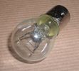
Land Rover Stop Tail Light dual filament bulb nominal 12 volt 21 / 5 watt filaments1427 viewsThis is the Land Rover part number 264590 dual filament bulb, (P21/5), that inserts into the upper two tail lamp receptacles. In the upper one, both filaments function, in the lower one, only the 5 watt tail light filament functions.
I regard it as not a good practice to routinely switch bulbs when the tail light filament, (5 watt), burns out on the lower bulb. The broken filament can jiggle over onto the brake light filament, (21 watt), and short the circuit to ground or something else not predicable.
There are also arguments to say that quality control is better on the Land Rover marketed bulbs than say far east sourced bulbs. Filament construction, and hence resistance can vary and mislead the current sensing circuits monitoring the signal light systems. Also when the bulbs are properly installed, all filaments should be standing vertically and not at any slope.
These are the sort of obscure circumstances that can lead to false trouble messages on the display, dropping to the stops, and subsequent concerns - all over a tail/signal light bulb.
For example, the filament life of both the tail light and the brake light filaments in the P21/5 bulb is significantly less than the USA common 1157 dual filament bulb, (1000/250 vs 5000/1200 hours); brightness in the P21/5 is a bit more, (3cp/35cp vs 3cp/32cp where cp is candle power), but current consumption is oddly less, (0.44a/1.86a vs 0.59a/2.10a where a is amps). It is the quest for efficiency vs maintenance trade off.
|
|
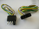
4 pin NAS flat connector from NAS small trailer382 viewsThe connector with the three exposed pins is the end that would commonly be located at the trailer hitch end, (front), of a small NAS lightweight trailer that has no electric brakes. This plug would connect into the flat 4 pin connector at the rear of the 3.
Note the order of the pin functions and wire colours: White is ground; the next pin is for tail/marker lights using the Brown wire; the Yellow conductor is for the left turn signal, and the far pin uses the Green conductor for the right turn signal.
There is no separate brake light conductor as NAS spec vehicles most often combine the brake and signal light functions to the same bulb filament rather separate filaments in different bulbs. The LR factory harness resolves that design difference.
Fortunately, the Land Rover NAS assembly pin order for the 4 pin flat plug maintains the above described conventions.
|
|

Alternator and Regulator Wiring Diagrams, TDV6 and petrol V8 and V61989 viewsThis is a three page pdf that shows the alternator and regulator wiring for the petrol V6, petrol V8 and TDV6. The pdf can be either printed or by right clicking on the displayed pdf, rotated as required for viewing.
Of interest is that the regulator gets its instructions primarily from the Engine Control Module (ECM) and only secondarily from the vehicles electrical buss. The conductor from the battery thru the 5 amp fuse F20E is to provide initial power to excite the alternator at startup and then secondarily, to instruct it if the PWM signals were not available. Primary instructions to and from the ECM are thru the two other conductors via a digital like Pulse Width Modulated (PWM) signal.
If F20E, the 5 amp engine compartment fuse box fuse is blown, the red alternator light on the dash will be illuminated. This means that the alternator could be OK, but if the F20E fuse is blown, no electricity will be generated. Hence check the F20E fuse if you get a red ALT light or some indication of the alternator not working.
Regarding operation of the red ALT light on the dash, it is not the regulator within the alternator that tells the red light to illuminate, or not, but instead the ECM. This is the reason the red light does not function in the same manner as with older vehicles. With the 3, sometimes you have illumination and sometimes not depending upon what the ECM is thinking. What this means is that you can have an alternator that is failing but the red light does not illuminate as the ECM is compensating for reduced alternator output - maybe by draining the battery and or cutting back on vehicle electrical loads such as shutting off or cycling the radio amplifier or heated seats.
|
|

Alarm System description and Operation1052 viewsThis 9 page pdf explains in detail how the anti-thief, (alarm), system is supposed to operate. The system uses the door ajar switches to provide alarm system signals; as such there are few separate contacts related to the alarm system only.
Page 6 of 9 is of particular interest as it describes the trigger log that is accessible with the dealer T4.
|
|
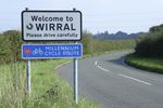
Thread upload9 viewsImage uploaded in new thread
|
|

House Sign?57 views
|
|

Wipers, Front and Rear, plus Washers description and operation.818 viewsThis 17 page pdf describes how the wipers, front and rear, plus the washers are intended to operate. Also described is how the rain sensor is designed to function along with a table of the wiper delay timing parameters.
|
|
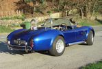
Replica AC Cobra 4276 viewsSelf design & build cobra 427 in a small house garage over a 4 year period. 515bhp & 3mpg if you push hard with the right foot. Track days were the most fun I've had with clothes on. Sadly she's gone to make way for the more sedate "E" type.
|
|
Thread upload16 viewsImage uploaded in thread 131653
|
|
Sign on road-side183 views
|
|

Land Rover Aerial Fin images for both Glass and Metal Roof Disco3 / LR3863 viewsAs well as the two different fins, this pdf also shows the plastic blanking plate for glass roof vehicles where no fin is installed.
The glass roof fin is secured by two security screws from the top into a plastic frangible glue on gasket. The hope is that when struck, the fin will shear off and not crack the glass roof. Re the metal roof design, the fin is secured from underneath via two nuts.
The pdf also shows the various electrical bits related to the antennas. In the UK, the fin would house not only a cell phone antenna but the TV and satellite radio antenna electronics as well; in the States, the Sirius sat radio antenna and a G type cell phone antenna if the phone kit was installed would reside within the fin. The SAT NAV GPS antenna is located within the High Mount Brake Light plastic mounted to the upper rear hatch.
|
|
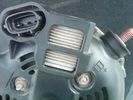
Alternator Plug and B+ terminal918 viewsPictured is the rear of the older Land Rover part # YLE500190 alternator showing the shiny cooling fin of the Regitar VRH2005-142 regulator under.
The first pin in the far left side of the connector is numbered #1 in the LR electrical wiring diagrams and is Battery Voltage Sensing (BVS); the middle pin, #2 receives a Pulse Width Modulated (PWM) signal from the Engine Control Module (ECM), and the right pin, #3 carries a PWM signal back to the ECM. Terminal Pin #2 on the LR wiring diagrams is called Alternator Control or ALT CON; Pin #3 per LR is called Alternator Monitoring or ALT MON.
Pin #1 is similar to what in older designs used to be called A or Batt, but is now called by Denso, S, AS, or Alternator Sensing for this design. Pin #1 also provides power to excite the alternator at startup until the PWM instructions over ride the battery voltage info. Land Rover calls the electronics under the pins a Smart Regulator, ironic, as it has to follow orders from the ECM rather than give the orders - new age thinking I guess. This is different from older design internal regulators that look at just the battery or the electrical buss voltage and then decides itself what to do.
It is almost like we are back to the external regulator designs of old, except that the ECM may decide that instead of telling the alternator to make more power, to load shed, and hence shut down the heated windscreen, seats, or whatever other electrical loads it decides are appropriate. My view is that the "smarts" are in the ECM and that the "regulator" should be regarded if not dumb, then as being a slave to the ECM.
|
|

Thread upload15 viewsImage uploaded in thread 174456
|
|

Thread upload9 viewsImage uploaded in thread 136164
|
|
Thread upload5 viewsImage uploaded in thread 202713
|
|

Frame Jacking Points showing where holes are located.1088 viewsThe four points marked with the arrows show where the holes in the underside of the frame are located such than one could insert a trolley jack pin type lifting adapter, (or as designed), the official LR scissors jack.
|
|

A Pillar Black Plastic cover install pdf - new type.1038 viewsThis 3 page LR pdf explains how to install the newer A pillar plastic covers and avoid instant water leakage as a result of the new design.
|
|
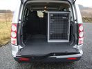
B24 TransK9 Dog Transit Box for Discovery 471 viewsThis box is designed specifically for the Discovery so that the 6th seat can also be used.
|
|

MY 4x4\'s powerd by BAS signature logo190 views
|
|

BAS Logo for signature use189 views
|
|
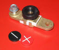
Battery Disconnect side post with + & - caps, top view617 viewsThis disconnect is designed for side post batteries. It can be used on either the + or - terminals. It can also be installed at the "other" end of the battery cable as well. In my install of the Aux battery, I installed this on the negative ground cable where the cable attaches to the body sheet metal. I have never used it but it seemed like a good idea at the time. The main battery hookup is pure stock.
For the hot side of the Aux battery, an Anderson PowerPole was used inline for the cable between the Aux and connecting to the spare bolt hole at the + post of the Main battery cable.
|
|
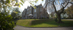
Woodlands Hotel6 viewsGreen Oval Garage would like to say thank you to the Woodlands Hotel in Leeds for allowing us the use of their beautiful grounds for all our future photos shoots.
Woodlands is one of the finest luxury hotels in Leeds. This boutique hotel is set in beautiful landscaped grounds on the outskirts of Leeds city centre, just 2 minutes drive from junction 27 of the M62 motorway, with 23 individually designed bedrooms and an award winning restaurant. Packed with character, this lovingly restored hotel is only three miles from the vibrant, cosmopolitan city of Leeds with superb nightlife and unrivalled shopping.
Woodlands also offers a stylish and contemporary functions venue for all kinds of social and business events. Our three stunning event spaces are suitable for everything from wedding ceremonies and receptions, to corporate meetings and events. The permanent marquee, attached to the hotel, can accommodate up to 150 for dining and 200 for evening parties and receptions, making it one of the most elegant settings for a wedding venue in the Leeds area.
For more information or to make a booking, please contact us on enquire@woodlandsleeds.com or 0113 2381 488
|
|

111 views
|
|

112 views
|
|

Thread upload7 viewsImage uploaded in thread 159579
|
|

Thread upload2 viewsImage uploaded in thread 194599
|
|

Thread upload1 viewsImage uploaded in thread 192626
|
|

Thread upload7 viewsImage uploaded in new thread
|
|

Brake Light Switch, Find, Remove, and Install Instructions 7853 viewsThis is a two page doc outlining where to find the brake light switch, how to remove it, and then install the new one.
Note, do not move the brake pedal when removing or installing the switch. Let the brake pedal hang where it wants to. The switch design is actually cunning, and as such is supposed to make the removal and install fool proof. Hence if you think too much about it, you can wreck the new switch.
If you want to inspect the interior of the switch, wait until you have removed the old switch. You can then just unsnap the blue from the white to get it apart. Inside, the switch is quite simple, (no circuit boards), but it will probably show black dust from failing contacts.
I think the reason the switch fails is that the Normally Open, (NO), contacts of the brake light contacts were made too light to carry the current load for make and break of the tail light filaments. I also think the black dust created then fouls the Normally Closed, (NC), second set of contacts for the ABS circuit. As such, the Normally Closed contacts become intermittent in operation and display as a fluctuating open and closed circuit condition to the ABS system when the ABS should be seeing a steady closed circuit. Hopefully the replacement switch contacts are more robust and may be as I recently replaced my switch again just as a matter of maintenance. While in a redesign, ideally the NC contacts should be sealed or at least separated from the NO contacts, when I inspected the removed switch, this time there was no black dust present.
Probably the removed switch will have a Land Rover oval logo moulded into it, the new one, FOMOCO.
|
|

Thread upload142 viewsImage uploaded in thread 174456
|
|
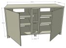
Cabinet design165 views
|
|

Thread upload3 viewsImage uploaded in thread 182352
|
|
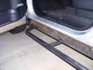
Sill protectors 2740 viewsThe side protection bar comes out a good 170mm. Prevents side panel damage and car-park knocks! Still deciding whether to fit the chequerplate tops, as originally designed.
|
|

69 views
|
|
85 views
|
|

56 views
|
|

Thread upload15 viewsImage uploaded in new thread
|
|
107 views
|
|

139 views
|
|
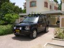
RHS view371 viewsSHows the Front Runner (SA) slimline windcheetah rack which is immensely strong. Takes my 110kg (oh gawd, I must get back on the diet and exercise regime) tramping over it when loading/unloading gear without a problem. Fittings are simply fixed or removed, and IMO very well designed and made. IPF 800 series driving and spots fitted to the front of the rack. IPF cam/reversing fitted each side and to rear of rack for negotiating rocky wadis at night. The G4 stickers were bought off E-bay as a set.
|
|
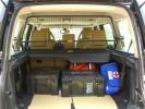
Load space368 viewsShows the SA Front Runner Wolfpack stacking plastic storage boxes that I keep laod straps etc in and the 2nd is tool kit, spare belts, jerry can funnel and tools, plus airline and tyre inflator/deflaotr for ARB on-board compressor, HD jump leads. ARB Winch pack (Orange)with strops, snatch blocks, shackles, gloves, and 2 ARB recovery dampers. Really great 4x4 1st Aid kit from Outdoors warehouse in SA. LRs own loadspace guard - not the best design if you want to store a long load. Mods to be carried out!
|
|
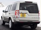
The D4 cluttered signage on the tailgate154 views
|
|

sign for winter tires 17 viewssign when winter tyres are mandatory in Czechia
|
|

czech road sign winter tyres19 viewsczech road sign winter tyres
|
|
Thread upload29 viewsImage uploaded in thread 167874
|
|
Tap in to C2443 pin 3167 viewsC2443 pin 3 provides easy access to the high beam signal from MY14 onward. My13 and earlier the signal has to be taken from C583 Pin 34 (CJB)
|
|

Thread upload2 viewsImage uploaded in new thread
|
|
21 views
|
|

Cooling System - Description and Operation 4.0L and 4.4L petrol engines 5 pages1028 viewsThis is a 5 page pdf that provides some insight into how the coolant flows thru all the hoses. Of interest is the paragraph,(page 3/5), that attempts to explain how and why the thermostat is designed to open at different engine operating temperatures - in brief, the reason for the spaghetti tangle of small hoses on the top of the engine.
There is also reference to an engine oil cooler that I gather cools something I think related to a supercharger, if fitted.
|
|
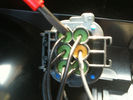
190 viewssignal wire pin 3 on rear of D4 rear light plug fit 6 ohm 50 watt resistor across here and common ground Pin 5 yellow terminal shown in next pic
|
|
Discovery 3 rear underbody protection111 viewsDiscovery 3 rear underbody protection wich I designed and draw.
|
|
Discovery 3 Underbody protection109 viewsDiscovery 3 rear underbody protection wich I designed and draw.
|
|
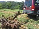
LR3 to plow your garden297 viewsI found this jpg where a current LR owner is using his LR3 for a similar purpose as the original Series units were designed to do - that is serve as a tractor for plowing a field or I suppose a garden.
In this case, I note the hitch is one of those that attach to the factory tow loop, (Rhino Hitch), rather than the factory product that inserts from the bottom and hangs down - (like a plow), but all the time. One of the other jpg's in this album shows the two factory variations plus a third jpg shows a closeup of the Rhino Hitch.
|
|
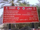
good to know that \'drowning accidents are now popular\' - signpost near the pool139 views
|
|
Walking Stick (Insect Order: Phasmida)53 views
|
|
design with a lamp at night37 views
|
|

design with a lamp at night.34 views
|
|
design with a lamp at night..35 views
|
|
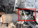
Detail of hydraulic hoses attached to power steering hoses155 viewsHoses are attached to the upstream side of power steering rack. When winch not running, PS rack sees full pressure (ie, no change from design). Biggest challenge is running stiff hoses so that they align with attach points. I got Qantas employee who repairs hydraulic baggage loaders to braise in fittings (very tight spaces and tough access).
|
|
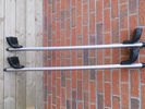
Showing manufacturers designed profile in bars.21 views
|
|
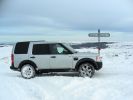
CALENDAR 2010315 viewsFebruary 2009. Glaisdale Rigg.
As it says on the sign, "2 miles from Lealholm, 7 miles from Rosedale!"
North York Moors.
|
|
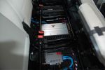
amps and signal processor321 views
|
|
Accessing the signal processor368 views
|
|
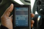
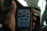
EQ for signal processor.. accessed through a palm PDA313 views
|
|

26 views
|
|

38 viewsGiancarlo e signora più Lady Crazy alle prese con le tagliatelle
|
|

37 viewsGiancarlo e signora alle prese con i ravioli
|
|

23 views
|
|

Thread upload10 viewsImage uploaded in thread 133664
|
|

223 viewsDesign of 18" rim to fit D4 3.0 ltr
|
|

Thread upload8 viewsImage uploaded in new thread
|
|
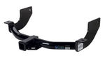
Curt Manufacturing brand hitch, assembled but not installed.290 viewsThe Curt Manufacturing hitch is an alternate to the Land Rover removable "plow" hitch. Once bolted in place, the Curt hitch is always there.
The Curt part number is 13456. It is a Class III hitch with a 2" square receiver and designed for a maximum 600 pound tongue weight.
The hitch hangs below the rear bumper but does not stick out past the bumper; also the "donut" spare tyre can still be installed / removed; am not so certain about a full sized fully inflated spare.
|
|
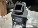
Rhino Tow Loop Hitch269 viewsThis is a receiver end view of the Rhino Hitch that ties to the factory tow loop. In addition to improved strength, it does not reduce ground clearance as does the factory style when installed.
Land Rover in early advertising videos when the 3 first came out showed the D3 hanging from a crane via the frame. The intent was to show how strong the frame is and by inference, the rear tow loop, specifically noted as being good for 6 tonne. The video ends before anything dropped or was lowered back to the ground, so one of course does not know for certain. The Rhino Hitch design however picks up on the apparent evidence of strength and certainly the additional clearance.
|
|
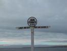
"The Icon". The man in the hut that does your sign ,, had gone home ..155 views
|
|

Thread upload198 viewsImage uploaded in thread 162283
|
|

signs35 views
|
|

Croc Sign, Ord River, WA, Aust123 views
|
|
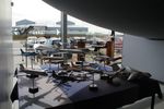
Various Avro failed designs19 views
|
|
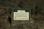
Road sign55 views
|
|
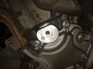
Old pump design has a weak point on the tensioner mount12 views
|
|
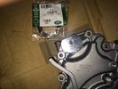
New pump design has the reinforced casting for the tensioner mount13 views
|
|
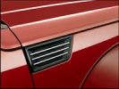
2007 Dodge Nitro - where did they get that design cue from?256 views
|
|

Thread upload8 viewsImage uploaded in new thread
|
|

L319 - The Design Case Study29 views
|
|

134 views
|
|

LED trailer lights adapter for LR3843 viewsThis doc includes a partial list of materials and the instructions/links required to construct an adapter to prevent LED trailer lights from pulsing due to the 3's diagnostic circuits interrogating the signal light circuit.
Using the adapter also facilitates the green flashing of the dash located trailer indicator when the signal lights operate plus inhibits operation of various systems such as the backup sensors, etc.
|
|

Littelfuse Add-A-Circuit MINI and ATO style data sheet150 viewsPDF from Littelfuse showing both the MINI and ATO style of fuse holders. The 3 uses the MINI size of fuse. The MINI Add-A-Circuit can be inserted in place of one of the existing fuse panel MINI fuses. The removed fuse is then inserted into the lower slot of the Add-A-Circuit and a second fuse in the second slot to protect the device that you are adding. The Add-A-Circuit is designed for a max of 10 amps on the second load, and I guess maybe the original circuit as well.
|
|

LLumar "windscreen" clear Infra Red reduction side window film930 viewsThis is a data sheet on the LLumar brand of what they call Windscreen Film; It is almost clear, (has a bit of a blue tint), and reduces both the Ultra Violet fading and sun burn rays which most all films do as that is easy, plus more significantly, the Infra Red heat rays. That is rare as it is not so easy or cheap to do.
AIR80BLSRHPR (blue) is what the IR rejection film is listed as in the brochure that I used. http://www.llumar.com/en/AutoWindscreen.aspx
I had it applied to the front side windows as well as the front sun roof. One can feel the difference when the sun is low and streaming thru the side glass or high and coming thru the sun roof. Rolling a side window down is the simplest test of effectiveness re the rejection of the heat energy.
|
|

EPB Failure Analysis472 viewsDocumented dissection of failed screaming EPB showing fundamental design flaw and use of inappropriate materials.
|
|
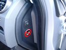
Air Suspension ECU Fuse 35P cut off switch.3820 viewsThis shows the SPST rocker switch mounted in the blank plate installed in lieu of a manual passenger side air bag shut down switch - now automatic via passenger seat pressure switch. Fuse 35P (5 amps) is located in the interior fuse box behind the lower glove box and protects the ignition power supply to the Air Suspension ECU. When the SPST switch is moved to the OFF position, the RAISE /LOWER switch on the centre console is not powered, and hence does not function. As such, some signals from the wheel height sensors and CPU are ignored. By itself however, removing F35P will probably not stop the 3 from self dropping, particularly after the engine is turned off.
Fuse F3E, (5 amps), located in the engine bay fuse box by the starting battery protects the circuit that provides feedback to the Air System ECU indicating that the Compressor Relay has successfully operated and that the Air Compressor is or should be operational, can also be removed, (but is probably not totally necessary), as it gets its power thru F26E. Hence Fuse F26E, (20 amp), also located in the engine compartment fuse box is the fuse that must be removed. This fuse protects the circuit that provides full time battery power to the Air System ECU. When in place, current thru the fuse powers the periodic re-levelling action, (usually lowering a bit with that brief air release noise), that often occurs when the vehicle is parked and the engine is off.
Removing F26E fuse will stop the auto levelling action and also inhibit any other down to the stops signals, (engine running or not). When F26E is removed, no power can flow thru to F3E, hence removing F3E is more for insurance than an absolute requirement. The same with F35P, removing F26E removes primary full time power from the Air Suspension ECU, and hence removing the F35P fuse should not really be required either as long as F26E has been removed.
|
|
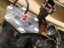
Compressor Electrical Plugs 1406 viewsThis shows the two electrical connectors; the two pronger is the power to the compressor, and the multi-pin connector carries control signals. Also the temporary red plug is where the 6 mm tubing from the centre valve block connects. This line carries both the compressor and exhaust air to and from the springs.
|
|

NAS 7 Pin Round Socket + 4 Pin Flat Socket oriented as installed.752 viewsThis is the layout you see when you look into the NAS Land Rover sockets as installed at the rear of the LR3/4. The flat 4 pin socket is located under the round socket.
Wiring order is relative to the slot on the round socket, and hence the same as the other jpg where the slot is shown at the top.
The CJB monitors the front and rear turn signal lamps and can detect if more than four lamps are fitted, (the side turn signal lamps are not monitored). This is another reason for using genuine LR bulbs as off shore bulbs can have varied and out of spec resistance values.
When a trailer is detected, the trailer warning indicator in the instrument cluster is supposed to flash green in synchronization with the turn signal indicators.
If one or more of the turn signal lamps on the vehicle or the trailer are defective, the trailer warning indicator will cease to flash any longer. This is to alert the driver to probably bulb failure.
If the trailer has LED lamps installed, and no LED adapter circuitry is used, most likely the trailer will not be sensed and systems such as the backup sensors will not be disabled.
|
|
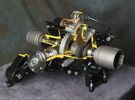
Rear Differential cutaway with E-Locker 1210 viewsThis jpg is from the link below.
There are another ten or so cutaways plus a whole file group showing a 2005 LR3 sectioned for the 2005 Chicago Auto show. Each jpg has an enlarge function to the bottom right of a main picture.
On one jpg you can see right into the stepper motor.
http://www.cutawaycreations.com/cutaways.php?project=land-rover-electronic-rear-differential#/IMAGES/car4/images/image1.jpg
Both the front and rear differentials are manufactured by Dana Spicer in the UK. Dana calls them a Clamshell design.
|
|
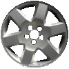
LR3 Sparkle Silver 6 spoke Wheel Cromodora of Italy 19 inch x 8 ALY72191U1108 viewsThese are the standard equipment 19" wheels on the 2005 LR3 HSE. The wheels are Made in Italy by the Cromodora company. Each are rated at 940 kg (2,072 pounds) and have an offset of 53 mm positive, (53P or +53).
I mention the 940 kg load rating as that is about the heaviest rating of any Land Rover product. The RRS and RRHSE both have lower ratings. What this means is that while a wheel from a Range Rover may physically fit, it probably does not have the brute strength of the factory spec Land Rover 3 wheel. There is no Land Rover product heavier than the 3, hence the 3 wheel design spec is the heaviest of the bunch.
|
|
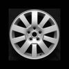
LR3 Sparkle Silver 10 spoke Wheel Cromodora of Italy 18 inch x 8 ALY72190U727 viewsThese wheels are factory standard on the 2005 LR3 SE and Made in Italy by the Cromodora company. Each wheel is rated at 940 kg (2,072 pounds) and has an offset of 53 mm positive, (53P or +53).
I mention the 940 kg load rating as that is about the heaviest rating of any Land Rover product. The RRS and RRHSE both have lower ratings. What this means is that while a wheel from a Range Rover may physically fit, it probably does not have the brute strength of the factory spec Land Rover 3 wheel. There is no Land Rover product heavier than the 3, hence the 3 wheel design spec is the heaviest of the bunch.
|
|

lr3-kaymar-closed with 20"405 viewsthe kaymar carrier, designed to allow two tires, sets them both a bit outboard, thus blocking the lamp. that\'s when I realized why they put the fully functional lamps in the bumper (functions: running, brakes, signals, hazard)
I plan to re-weld the locating section more towards the middle of the rear similar to Disco II orrientation.
|
|

LR3 Denso Alternator YLE500390 pulley view819 viewsNote the DENSO sticker on the side. Denso calls their nominal 150 amp 12 Volt alternator an SC2 design. SC means Segment Conductor which apparently increase the winding density of the stator coil, hence yielding a physically smaller lighter alternator for a given output. I presume the 2 means the second try at getting it right. A Denso part number is 4280003690 for the alternator, (there are others, as below).
Rotation is clockwise and the 54mm diameter pulley has 6 grooves (PV6x54). Count the pulley grooves on both the one you remove and your new one - some replacement alternators seem to ship with 5 or 7 grooves so you might be swapping pulleys.
A previous LR part number was YLE500190 for the older variation of the newer YLE500390 unit.
An additional part number for a factory rebuilt is Nippon Denso 210-0569 for the petrol V8 alternator. Other Nippon Denso numbers include 104210-3690 and 104210-3691. The Lester number is 11206 which relates to another Denso number of 290-5287. WAI uses 11206N.
From 2006 to 2009, the internal regulator is a Transpo IN6349 and of the B circuit type if it can be said that applies to PWM, (Pulse Width Modulated), regulators.
The "regulator" inside the alternator is therefore really not a regulator in the old sense of the term but instead an instruction receiver from the ECM that translates Pulse Width Modulated (PWM) signals into a form that the alternator understands – digital like signals from the Engine Control Module(ECM) into analogue like signals that the windings understand.
|
|

LR3 Denso Alternator YLE500390 rear view709 viewsThis picture shows the rear of the YLE500390, the Land Rover part number for a newer design alternator utilizing the Transpo IN6349 regulator with the "hidden" cooling fins. Note the visual difference in the rear view of the next file jpg.
If the alternator is a rebuilt, (service exchange unit), but Land Rover supplied, then the part number is LR008860 or similar. (Note that 0 in LR0 is zero.)
Two Denso part numbers exist for the alternator as well, 4280003690 and 4280003691. The rating of the petrol V8 alternator is nominal 12 VDC and 150 amps. In normal day to day operation, they seem to run about 14VDC - usually between 13.9 and 14.1 volts at the OBD port.
For the petrol V6, the LR service exchange number is LR008862, and the 2.7TDV6 is LR008861.
The bridge rectifier within the alternator is a 12 diode avalanche type, 117mm diameter, as used in Nippondenso 120 to 160 amp alternators with the Hair Pin stator. It is similar to a Transpo INR421 which is rated for 120 to 150 amp alternators. That is probably our primary problem - the rectifier is just too light. Alternate part numbers for the bridge rectifier are Cargo 237607, Mobiltron RM-29 and AS ARC6021.
Re the B+ stud, the INR421 calls it up as an M8 x 1.25 x 30 mm long course threaded stud; some say 34 mm but that may be longer than desirable.
|
|

Power and Heated Seats Electrical Schematic979 viewsThis 6 page pdf shows the wiring for the power adjustment of the front seats and seat heating for all the seats.
Re seat movement or the lack of, not only are there four related fuses, two 30 amp and two 5 amp, (one of each per seat), there are are two separate ground wires, perhaps of more significance than the power, if all movement on either side quits.
|
|

Stop Light Lamp Circuit pdf2491 viewsThis pdf shows the brake light circuit for the NAS LR3.
Note that power for the brake light bulbs can come either thru the brake light switch power feed /contacts plus also from the Hill Decent Control, (HDC), system relay located within the Central Junction Box, (CJB) - yes two separate sources of power for the brake light bulbs. This would tend to explain how a brake light circuit concern shows up as a hill decent fault message; also why lesser vehicles without hill decent braking mechanisms, (HDC), never display this sort problem when a brake light bulb or switch acts up. You never have a problem related to a system that does not exist.
Additional evidence of the relationship of the HDC and the tail light circuit is demonstrated by when the HDC actually acts to slow the 3 down, the brake lights automatically illuminate even if the slowing action was merely retarding the engine speed or shifting to a lower gear, (in other words, no foot on the brake pedal).
There is also a tie in to the Cruise Control and hence a failing brake light switch can affect cruise operation or just create false Cruise Control messages. To further complicate the issue, while there are no messages generated, operation of the radiator electro viscous fan can also be negatively affected by the fouled set of secondary contacts within the brake light switch. This is all because the NC contacts within the brake switch send misleading messages to the ECU.
While the ground wire design is similar to other vehicles, note the grounds for the brake light filament and the reverse light filament are common on each side. That means that if one has a non functioning brake light on one side, the reverse light may not also work or that some problem with the reverse lights could back feed into the brake lights. This situation while unusual, can result when grounds are corroded probably due to swimming in rivers and creeks or just routine driving in a marine environment.
|
|

LSE Design108 views
|
|

LTB00199 - Technical Bulletin - Battery Vent Tube Blockage - New Design Repair Procedure63 views
|
|

Thread upload23 viewsImage uploaded in thread 107857
|
|
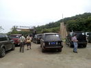
the sign says are you ready62 views
|
|
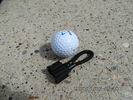
MOST fiber optic loop tool468 viewsThe looping tool in the jpg uses the Land Rover type plastic fiber optic cable with both ends feeding back into a female fiber optic connector that mates with the male fiber optic connectors on the Land Rover system.
The purpose of the loop is to allow one to disconnect MOST connected items such the BlueTooth module or the HK amplifier but allow the MOST system to still transmit signal from the head unit as the circuit would remain closed and hence complete. Of course with the Bluetooth module disconnected, there would be no Bluetooth available, however the radio and NAV would still function.
The looping tool allows one to troubleshoot the system by removing one component at at time from the MOST loop. In other words, what might appear to be a radio problem could be a Bluetooth problem - that sort of thing.
|
|
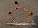
Fibre Optic MOST cable between components.560 viewsThis is a typical section of Plastic Optical Fiber (POF) optic cable with the orange coloured cladding covering the perimeter of the light transparent core. This is used as the MOST (Media Oriented Systems Transport) data transmission medium.
Note that each MOST 1355426 optical connector holds a pair of light conductor cables, one transmitting optical signal in, and the second, optical signal out. When connected to the other cables and devices, the cables form a continuous loop.
The light signal within the cable is red colour as one might expect. One break or disconnect anywhere along the loop shuts down signal transmission to all the connected components.
|
|
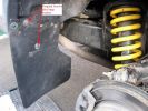
Fitting Land Rover Series 3 Rear Mud Flaps to a Disco 3/4 - A956 viewsUsed Original Screws plus two extras, Had to cut around exhaust. Once first done, laid them back to back and used first as a template to drill and cut second. Used a 5.5mm drill for the holes in the flap for the original screws and a 7mm drill to make the new holes in the plastic wheel-arch trim and lining to take the two-part trim clip (see my gallery for a picture of this style clip) - this photo of the new flap shows two screws but I modified that design to avoid using screws which corrode with time. Ignore the fact the pics are taken on a D3 Coiler, it makes no difference.
|
|
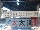
Tokyo Fish Market (although this may be the fruit n veg sign...)227 views
|
|
Thread upload0 viewsImage uploaded in thread 166816
|
|

Office Off Road Sign155 views
|
|

Office Off Road Sign147 views
|
|
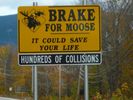
vermont101 viewsmoose crossing warning signs in vermont
|
|
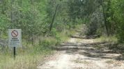
Pine Road - Road closed sign108 viewsForestry track/road (11 km north of Iluka turnoff along Pacific Highway) but blocked about 3 km along. Took Thompsons Road to rejoin highway but had to negotiate a swampy area with fallen trees across track. Road impassible without chainsaw so found a private road and headed towards Glencoe Road using a Telstra track.
|
|
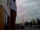
Parking Sign54 views
|
|

35 views
|
|
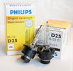
Philips D2S 85122 C1 Xenon 4300K projector HID bulb962 viewsThis is the 4300K OEM bulb in our HID Xenon projector headlights. People who design illumination systems regard the 4300K colour as a good compromise to provide what is called definition. This is effectively the ability to actually determine what an object being illuminated probably is. The more blue colour bulbs, say 5000K and greater, result in a reduction in the ability to distinguish detail, (regardless of brightness), of the object being illuminated. Effectively, you can see the object but you cannot quite figure out what it is. This is because the more blue frequencies means there are fewer other frequencies of light that allow our eyes to actually discern what an object really is.
The 4300K colour temperature applies to clear air conditions; for rain, dust, snow, fog, etc, then a yellow 2500K colour temperature is preferable. 2500K provides more contrast and there is less back splash of light off the air particles. In blowing snow, this means less sparkle back. Flat top cut off of the light beam, (which is the pattern our projector lights have), is important to reducing back splash - hence you do do not want roof mounted lighting for adverse conditions - as low down as possible is preferable, (which is why fog lights generally sit low.)
|
|

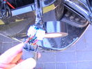
D4 Light Resistor54 viewsD4 LED Rear Light Resistor to avoid fast turn signal
|
|
216 viewsNeat design, very robust.
|
|

Outside Houses of Parliament208 viewsIt felt like my car had a big neon sign on it today driving in to Central London!!!!
|
|
i took power for camera and the reversing signal from the main loom with scotch locked365 viewstape them up otherwise they will corrode. this area gets wet and dirty
|
|

61 views
|
|
Thread upload16 viewsImage uploaded in thread 126278
|
|
Thread upload5 viewsImage uploaded in new thread
|
|
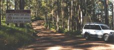
Huh?157 viewsPhoto that informs drivers that there are speed limits (50km/h) in built-up areas of Queensland. Sign was about the size of the car and traffic on this road was minimal. Wondered if the powers that be had only one size sign and whether there was a procedure that stated that the sign must be placed so that you couldn't miss seeing it as you entered this part of Queensland.
|
|

Transpo pdf explaining the operation of Ford PWM regulators624 viewsThe 4 page pdf produced by WAI-Transpo explains the operation of the Pulse Width Modulated regulators located within the alternators on our 3's. Of note, the pdf states that certain of the Ford PWM regulators do not meet Ford spec.
The pdf explains the function of all the terminals and the apparent advantages of the PWM style over previous designs. Note that Ford calls their "engine computer" a PCM, (Power Control Module), whereas Land Rover, an ECM, (Engine Control Module).
|
|

Transpo Regulator IN6349 Pin Assignment715 viewsThis pdf shows the Land Rover and Ford pin naming for the 3 pins in the receptacle of the Transpo IN6349 regulator that accepts PWM signals. This jpg is as if you are looking into the receptacle located on the alternator.
Also provided are the Transpo pin names that are in common use and that some may be more familiar with plus some comments re testing.
The IN6349 regulator is used in the newer LR part # YLE500390 alternator. For the older YLE500190 alternator, the regulator is a Regitar VRH2005-142 unit that is shaped a bit different than the newer IN6349 regulator. Externally, the main difference is that no shiny fins are visible on the rear of the newer YLE500390 alternator. The pin naming and numbering is the same for both and both alternators are interchangeable.
|
|
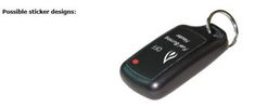
RF Remote 23 views
|
|

51 views
|
|
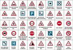
Road signs53 views
|
|

Pattern for Expo Roof Rack Floor Sheet397 viewsI used a 3mm sheet of Aluminium - with 150mm wide Grip Tape to do the Chevron Patter to make it a bit safer. Note the sheet is 1610mm long, 1100mm wide at the front and 1060mm wide at the back. I drilled 3 rows of 5x 12mm holes - one row down the centre and one either side 30mm in from the edge. The hole centres being at 31mm from the front edge, next 420mm from 1st hole centre, the 375mm from 2nd hole, 372mm from 3rd hole, 375mm from 4th hole, leave 31mm to the back edge. Edited May 2008: I've subsequently cut the sheet in half lengthways to make removal and fitting easier as I found the sheet increasing noise and reduces MPG considerably.
|
|
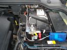
153 viewsI routed the white signal wire from the junction box which I positioned at the side of the battery, back and under the bonnet seal.
|
|
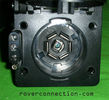
NAS 7 pin + NAS 4 pin Flat Trailer Socket308 viewsThis is the vehicle end of the NAS trailer harness that is located behind the removable plate centered within the rear bumper by the towing loop. Re the four pin flat connector, from the bottom, the exposed bare lower pin is the ground, usually the White wire on a NAS trailer. The next pin up is normally a Brown wire on a trailer and is for the Tail Lights. The third pin, normally a Yellow wire, is the left signal light; the top pin, normally a Green coloured wire, is the right signal light.
Re the round connector, from the notch in the plastic surround, clockwise, the first blade is ignition controlled +12VDC battery power, (only alive when engine running), and on the Land Rover factory harness is an Orange wire; on a NAS trailer, usually Red but perhaps a Black wire.
Next blade clockwise at 3:00 o'clock above, is the Right Turn signal light, a Green wire on the LR harness, and also on a NAS trailer.
At 5:00 o'clock, the next blade is for the Electric Brakes and is Blue on both the LR harness and on a NAS trailer.
The Ground wire is next, White on both the LR harness and on a trailer.
At 9:00 o'clock above, is the Left Turn signal, Yellow on both the LR harness and on a trailer.
The last blade to the left of the line up notch is the Tail Light circuit. On the LR harness, the wire colour is Brown with two White stripes and on a NAS trailer, Brown.
The centre pin is for the Reverse Back Up lights and is Black on the LR harness and often Purple on NAS trailer wiring but can be Black also.
Note that when the socket assembly is installed on the 3, the notch in the plastic surround is on the left - that is rotated 90 degrees anticlockwise to the picture above. In other words, When installed on the 3, the 4 pin flat connector lays horizontal and is located below the round socket.
|
|
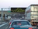
Highway Sign125 views
|
|

17 views
|
|

Thread upload20 viewsImage uploaded in new thread
|
|
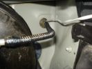
120 viewsThe signal wire then drops into the aux battery box and through the bulkhead grommet
|
|
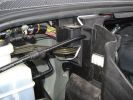
Signal wire through aux battery box to grommett123 views
|
|

Thread upload8 viewsImage uploaded in new thread
|
|
Thread upload10 viewsImage uploaded in new thread
|
|

Thread upload10 viewsImage uploaded in thread 154757
|
|
8 views
|
|
Thread upload4 viewsImage uploaded in new thread
|
|
Thread upload7 viewsImage uploaded in new thread
|
|
Thread upload14 viewsImage uploaded in new thread
|
|
Thread upload26 viewsImage uploaded in new thread
|
|
Thread upload29 viewsImage uploaded in thread 154757
|
|
Thread upload7 viewsImage uploaded in new thread
|
|
Thread upload15 viewsImage uploaded in thread 1546
|
|
Thread upload12 viewsImage uploaded in thread 1546
|
|
Thread upload12 viewsImage uploaded in thread 1546
|
|
Thread upload12 viewsImage uploaded in thread 1546
|
|

Thread upload11 viewsImage uploaded in thread 1546
|
|

Signs you see126 viewsI can't imagine many people wanting to eat potting mix, but just in case, this supplier wanted to cover their options and ensure that no one ate and sued as a result of thinking that you could eat potting mix.
|
|

SignUp66 viewsCome aggiungere l\'opzione per le iscrizioni
|
|

Thread upload2 viewsImage uploaded in thread 179252
|
|

20 views
|
|

Thread upload11 viewsImage uploaded in new thread
|
|

star signs15 views
|
|

Thread upload3 viewsImage uploaded in thread 142922
|
|
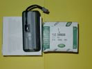
Upper Hatch Release Switch LR Part Number YUZ500020676 viewsThis is the Range Rover Sport switch, Land Rover part number YUZ500020, as it comes out of the box. Note the JAE, (Japanese Aviation Electronics), male wiring connector installed on the end of the power lead.
The rubber cover of the switch is sealed to the plastic body of the switch whereas in the previous switch design, there was no sealing. Also the replaced switch was hard wired into the same harness as the license plate lights - no JAE connector in other words.
|
|

Tekonsha P3 Brake Controller 90195 to Ford 3035-P wiring adapter plug311 viewsThis two page pdf is the general instruction for hooking up the Tekonsha part number 3035-P adapter cable between a Tekonsha P3 controller and the existing Land Rover/Ford plug, (called C2590 in the Land Rover wiring diagrams), that is hidden above the brake pedal.
The "Ford" plug, (C2590), is grey and is stuffed up above the brake pedal arm.
Mount the P3 controller appropriately and then connect one end of the custom cable to the P3 and the other to the "hidden" plug.
You will now have power for your trailer electric brakes in the round socket at the rear of your LR3; also no computer update from the Land Rover T4 unit is required. For once, it is plug and play.
If however, your trailer has LED tail lights, you may have trouble with the flashing of the trailer signal lights or non recognition by the 3 that a trailer is connected. As such, the little green trailer signal will not illuminate when a trailer is connected and the signal lights are used. This can affect the shifting of the transmission and much to your annoyance, the backup sensors will still be functioning rather than being auto disabled.
|
|
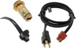
Block Heater and Cord for petrol V8 LR3 North America 120VAC529 viewsThe recommended 120VAC block heater cord is a Temro 3600003. This is a five foot long cord with what is called a Straight connector at the block heater end with holes for two pins; there is also a metal tab located between the two holes serving as the ground conductor. That cord, in addition to having the two pin holes plus ground tab end, is designed for both aluminum and brass heaters as that also matters.
The Land Rover part number for the Block Heater assembly is VUB504640 but is a Temro product not officially marketed by Temro as a Land Rover block heater. The Temro product number is 3100107 which shows as a brass body 30 mm threaded 700 watt 120VAC screw in block heater with a rectangular shaped depression and two pins suitable for the Temro 3600003 cord. Note the word BRASS as it mates with the aluminum OK.
|
|
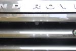
front view camera133 viewsThere is a small front view camera. which allows me to see the street and objects close in front of me. It actually is a D4 Rear view camera that turned out to be useless in the back because it did not produce a mirrored image.
In the front it looks like it is designed to be there.
|
|

White Ensign50 views
|
|

SIGNATURE38 views
|
|
188 views
|
|

163 views
|
|

Thread upload27 viewsImage uploaded in thread 104851
|
|
Amdeal 30ft / 10M USB Digital Microscope Cable Wire Endoscope Camera Video Recording Inspection Pipe Camera - Waterproof, 4 LED Lights27 viewsUnder XP system, can watch video directly without install software. By using our software, can take photo,record video, and save the video in the PC. Such USB microscope widely used to inspect tube, check the body, magnify stamps, coins, antiques, insects, electric circuits, machines, fabrics, food, decorations, etc. Please notice that the wire camera is designed for industrial use, not for medical use.
Camera: 1/6" VGA COMS
Pixel: VGA 300K
Resolution: 640x480,352X288,320X240,176X144,160X120
Capture Resolu
|
|
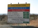
Road Conditions138 views
|
|
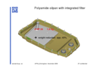
ZF_6HP26_Plastic_Filter_Pan_ combo.png1103 viewsThis is the plastic oil pan on the bottom of our ZF 6HP26X transmissions. Note the two round magnets at the right end of the pan; the drain plug is between them. The filter is the grey part and the vertical oil suction pipe is to draw oil up to the transmission from the filter element. There are 21 Torx screws around the perimeter and the pan gasket is O ring like in design where a half round channel is moulded into the plastic of the pan. The metal pan uses a more conventional flat gasket and in both cases, the metal mating surface of the transmission case is a flat machined metal surface.
|
|
|
|
|