| Search results - "Release" |

2010 D4 Official Release Notes158 views
|
|
egret release86 views
|
|

Thread upload18 viewsImage uploaded in thread 115513
|
|
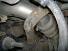
Charge Air Pipe - turbo end.101 viewsThe maint manual identifies releasing the pipe hose clip in the center of the photo. Pity who ever built this engine Put the hose in such a position that access to it was near impossible. I released the other clip at the turbo end of the flexi hose. Easy to get to but a right git to release the hose of the turbo.
|
|

Got Released and on my way again!442 views
|
|
35 views
|
|

Thread upload58 viewsImage uploaded in thread 109478
|
|
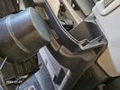
Bin Cover removed showing forward release clips that clip into the two rectangular slots.10 viewsOne has to pull up on the Bin Cover to unlatch the two metal clips, hence why release of the C pillar cover makes the bin cover removal and reinstall easier.
|
|
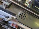
Buzzer located under black plastic cover.12 viewsThe white electrical connector clicks into the buzzer housing that is shown protruding from under the black plastic cover. There is a little tab on the white plastic that has to be squeezed to release the connector. In other words, do not pull on the two conductors.
|
|
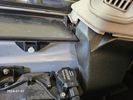
White plastic pin that has to be partly removed to assist in release of buzzer cover.10 viewsThe white coloured plastic pin is located near the C pillar and has to be partly pulled out to release the black plastic buzzer cover.
|
|
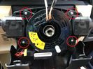
29 views
|
|
Thread upload5 viewsImage uploaded in thread 188726
|
|

282 viewsCradle in place. Press marked lever down to release the cradle.
|
|
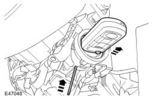
D3_Ignition_Barrel_Release23 views
|
|

Seat Base cover front and side clips released44 views
|
|

Discovery 4 From Press Release112 views
|
|

2 more awards for D3169 viewsMedia release from LRA - Dec 2008
|
|
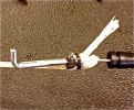
Pull cord as a backup63 viewsI added a pull cord so I would not kept caught with a broken release on the tailgate again. Think about a flat tyre if that happens to you.
|
|
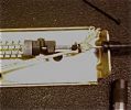
Actuator box underside 63 viewsUsed a clove hitch with plastic zip tie with 1/8" Kevlar rope
|
|
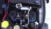
ARB CKMTA Twin Compressor180 viewsTwin Compressor with Manifold and Airtank. Tight fit but it fits. Also the ECU Chip is at the back and below up against the battery case.
I changed the hose quick release to a standard Air Hose Fitting eg like a workshop would use. My other truck has those also.
|
|
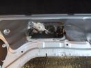
An alternative approach131 viewsDue to low temperature, and the size/mobility of my hands I decided that the easiest way to open the tail gate was to destroy the old Bowden cable and then pull centre core to release the tailgate - it worked, and doing this earlier would have saved a few cuts and grazes.
|
|
15 views
|
|
Thread upload20 viewsImage uploaded in new thread
|
|

D5 Emergency Hanbrake Release46 views
|
|
178 views
|
|

162 views
|
|

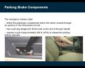
EPB Maual Release223 viewsEmergency Release procedure
|
|
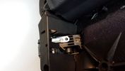
Fixed shelve release 26 views
|
|

Thread upload1 viewsImage uploaded in new thread
|
|
Thread upload24 viewsImage uploaded in thread 139245
|
|
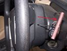
23 viewsPull the tool outward to release the clip.
|
|
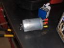
fuel filter 3133 viewsBlack knob loosens on bottom of filter to release water.
|
|

multi height tow bar2172 views
|
|

multi height tow bar1183 views
|
|
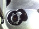
Bonnet Release27 views
|
|

Switch is blue colour thing thru the rectangular opening.3177 viewsThe blue coloured plastic bit thru the rectangular opening is the brake light switch. The fist time, I found it easier remove the switch by dropping the horizontal plastic panel, (two screws), and then slipping my hand in and rotating the switch clockwise 1/4 turn. The second time, I was able to remove the switch thru the rectangular opening and did not need to remove the horizontal lower panel. Obviously, I had to remove the sloping knee pad panel, (note sort of hinged at the bottom so pull back from the top.)
Regardless, do not touch the brake pedal - just let it sit where it wants to. One has to first remove the angled knee pad panel that sits under the steering wheel. It can be pulled from the top corner at the door side. Pulling releases a pair of those U shaped metal clips that LR loves so dearly. You have to pull quite hard. The bottom is held by a couple of plastic fingers in a couple of slots so you pull at the top till the two clips release and then rotate the panel and pull upwards a bit.
To remove the switch, you rotate it clockwise and pull outwards. Rotating the switch clockwise automatically retracts the plunger back into the switch body away from the brake pedal arm.
Similarly when you install the new switch, the required 1/4 turn anti clockwise rotation action releases the plunger so it lays up against the brake pedal arm and at the same time, secures the switch in place.
To remove the electrical wires, the switch will drop below the horizontal pad and hang from the wires so unclipping the electrical connector plug is fairly easy to do.
|
|

Possible to access the releases through this gap, I think26 views
|
|

Park Release36 views
|
|

Park Release27 views
|
|

Modified tailgate release57 views
|
|

InteriorReleaseCable22 views
|
|
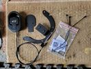
Thread upload6 viewsImage uploaded in thread 200461
|
|

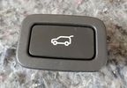
Replacement switch from RRS installed on LR3864 viewsThe switch shown is LR part number YUZ500020, the upper rear hatch release switch that is found on the Range Rover Sport.
The switch body is the same switch as on the LR3 except that there is no wiring disconnect on the LR3. Hence when the switch corrodes and requires replacement, the LR solution is to purchase a new handle and license plate light assembly. I instead cut off the old switch and installed a JAE mating connector to the existing wiring and hence just plugged the RRS switch in.
The replacement RRS switch snaps into the same rectangular space in the same manner as the removed LR3 switch, the difference is the JAE male wiring connector.
|
|

106 viewsFORD MOTOR COMPANY ANNOUNCES AGREEMENT TO SELL JAGUAR LAND ROVER TO TATA MOTORS
|
|
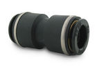
John Guest DOT all plastic fitting717 viewsThis is a picture of the John Guest DOT all plastic union. If you look closely, you can see the DOT imprinted in raised letters on the end of the fitting. This is of a 1/4" connector rather than the 6mm that the 3 requires.
The picture is similar to the air suspension pneumatic fitting union that Land Rover sells as replacement part # STC8580. This is for 6mm OD tubing size. The STC8580 comes with what are called "Collets" at each end that cover up the press to release feature underneath. See the John Guest web site www.johnguest.com under the Pneumatics section and also in Downloads for their catalog for install and remove instructions.
The actual "air brake spec" fitting that Land Rover provides has an interior 4mm OD ferrule that slips inside the 4mm ID of the nominal 6mm tubing. I have not yet been able to obtain the John Guest part number for the LR fitting, only the LR part number. This part number was generated for the RR Classic air systems.
|
|

John Guest (LR part # STC8580) push in straight 6mm tubing to tubing connector730 viewsThis picture is similar to the air suspension pneumatic fitting union that Land Rover sells as replacement part # STC8580. This is a 6mm OD tubing size push in to install straight tubing to tubing fitting. The STC8580 comes with what are called "Collets" at each end that cover up the press to release feature underneath. See the John Guest web site www.johnguest.com under the Pneumatics section and also in Downloads for their catalog for install and remove instructions.
The actual fitting that Land Rover provides has an interior 4mm OD ferrule that slips inside the 4mm ID of the nominal 6mm tubing. Hence the fitting depicted and part number are not actually correct. I have not yet been able to obtain the John Guest part number for the LR fitting.
The fittings that show in this doc are what I call food service fittings rather than transportation or Air Brake fittings. The part LR sells, (STC8580), is the Air Brake type for transportation.
|
|
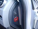
Air Suspension ECU Fuse 35P cut off switch.3820 viewsThis shows the SPST rocker switch mounted in the blank plate installed in lieu of a manual passenger side air bag shut down switch - now automatic via passenger seat pressure switch. Fuse 35P (5 amps) is located in the interior fuse box behind the lower glove box and protects the ignition power supply to the Air Suspension ECU. When the SPST switch is moved to the OFF position, the RAISE /LOWER switch on the centre console is not powered, and hence does not function. As such, some signals from the wheel height sensors and CPU are ignored. By itself however, removing F35P will probably not stop the 3 from self dropping, particularly after the engine is turned off.
Fuse F3E, (5 amps), located in the engine bay fuse box by the starting battery protects the circuit that provides feedback to the Air System ECU indicating that the Compressor Relay has successfully operated and that the Air Compressor is or should be operational, can also be removed, (but is probably not totally necessary), as it gets its power thru F26E. Hence Fuse F26E, (20 amp), also located in the engine compartment fuse box is the fuse that must be removed. This fuse protects the circuit that provides full time battery power to the Air System ECU. When in place, current thru the fuse powers the periodic re-levelling action, (usually lowering a bit with that brief air release noise), that often occurs when the vehicle is parked and the engine is off.
Removing F26E fuse will stop the auto levelling action and also inhibit any other down to the stops signals, (engine running or not). When F26E is removed, no power can flow thru to F3E, hence removing F3E is more for insurance than an absolute requirement. The same with F35P, removing F26E removes primary full time power from the Air Suspension ECU, and hence removing the F35P fuse should not really be required either as long as F26E has been removed.
|
|
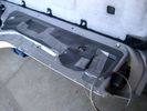
Dust Seal duct taped back together 2280 viewsThis shows the dust seal duct taped back together; also the surplus wire rope exiting from the actuator area prior to being cut to length.
I do not think the sticky plastic membrane is a dust seal, but more of a cable protector to cover up the wiring bundle that is effectively sticking to the underside of the flexible membrane.
|
|
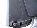
Flexible wire rope fishing leader 0.032" diameter exiting carpet 1947 viewsThis is all you see of the completed mod.
The short little angled "line" about an inch long that looks like a piece of debris and is located a few inches "above" the support cable is actually the wire rope release cable exiting from under the carpeted lift gate cover.
I drilled a very small hole in the carpet and pushed the 0.032" diameter release wire thru and then slipped the loose end under the black plastic.
To release with the lift gate etc closed, from the inside, just pull the loose end free from under the black plastic and gently pull wire about 5mm, (1/4"), and the upper door catch should release. You will have to manually push the upper door out wards to actually effect opening, but you will already be inside the rear cargo area so that part is easy to do.
The assumption is that the lower door latch still works electrically and hence, the lower lift gate half will open as normal by pressing the usual button on the top left of the lower door half.
|
|

Carpet Panel Removed showing Bass Speaker and Dust Shield 1733 viewsSomething is wrong with the orientation, however this shows what you see when the carpet is removed.
The dust shield, (under which the actuator is located), in the picture is as yet uncut. The white bit is the underside of the plastic lower lift gate carpeted cover panel.
The round thing is the woofer speaker for the Harmon Kardon radio. When the radio is working, one can see the speaker moving, but not much bass sound actually seems to emanate from the speaker.
|
|
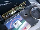
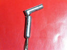
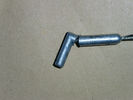
0.032" OD metal fishing leader and lead fishing weight clamped to existing wire rope 2118 viewsI used a size #0 lead fishing weight as a clamp to attach the 0.032" diameter flexible wire rope fishing leader to the release cable.
The pictured weight is the smaller #00 weight, however it did not work very well so reinstalled with the larger #0 size. I clamped to the cable as what breaks is the L retainer that is hidden in the actuator and holds the cable. When the L breaks, it lets go of the cable so you hear the clicking but there is no opening action.
Clamping on to the cable is an attempt to resolve that reality; also if the actuator electrically fails, the release mod should still do the task. Note in the picture the two Torx T15 screws that hold the gold plate to the plastic case and also the two 8mm cap screws that have to be loosened to remove the actuator from inside the door.
|
|
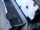
Carpeted cover removed showing uncut dust seal and underside of carpeted cover. 1628 viewsNote that there are all sorts of electrical wires sticking to the underside of the dust shield - so be very careful when you cut thru the shield.
I used a box knife very slowly and was surprised at how many conductors there were running just under the shield membrane.
|
|
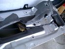
Dust seal cut; note electrical conductors right under dust seal 1627 viewsShows what is underneath when the dust seal is cut. Note the electrical conductors.
I used a box knife to cut the plastic and it was at first easy; then I seemed to hit something and fortunately I stopped - it was the wires - lots of them stuck right to underside of the sticky seal material.
Also shown are the two 8mm nuts in slots that you only have to loosen to release the gold actuator assembly.
|
|
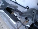
Dust seal rolled back showing electrical conductors 1658 viewsNote power conductors just under the dust seal which makes cutting the seal more interesting.
Also shown are the two 8mm nuts located in slots. One must loosen each nut to effect removal of the actuator. This will then reveal two T15 Torx screws that one must completely un-thread to remove the top gold plate from the actuator assembly.
|
|
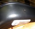
rear hatch light and door release switch390 viewswe\'ll ad a switch "guard" to protect from accidental gear shift popping button. light is slider 3 way so unlikely to be turned on by accident but will be nice down light when hatch is opened out.
|
|

Ashtray Slide6 viewsThis is a quick drawing describing how the ashtray stays in. There's a pin that rides through this channel, gets caught to stay closed, and pushing t in releases the catch.
|
|

Land Rover Brake Light switch XKB5001102699 viewsThis is what the switch looks like when removed from the parts box. Note that the plunger is recessed back into the body and when installing, the process of rotating the switch body 1/4 turn anticlockwise releases the plunger so it pops longer and engages the brake pedal. If you look down on the plunger you can see curved slots where the rotation takes place.
Do not try to rotate the new one - play with the one you remove. Also do not press on the brake pedal when removing or installing as you will damage the plunger - this is one of the reasons the plunger is retracted into the body for installation. It is also for this reason that if you try to confirm the operation of the switch contacts with an ohm meter by pressing the plunger, the switch will appear not to function as one might anticipate. Have faith, the switch will however, once installed and the plunger is in full motion.
|
|

181 views
|
|

134 views
|
|

Thread upload14 viewsImage uploaded in thread 149931
|
|

LTB00102 - Technical Bulletin - Driveline Clonk Noise after Throttle Release Reapply - Repair Procedure97 views
|
|

66 viewsThe cover that you remove to access the cable, for manual release of the electronic parking brake.
|
|

Noddy213 viewsOne of 4 Baby red kangaroos we are raising to release!
|
|
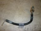
Negative Battery Cable208 viewsThis shows the corrosion from the negative terminal on the Negative to body ground. This is likely due to gas released through the negative post. It appears to be a common problem with the LR3. As a result of this corrosion left unchecked will damage the computer ecu and cables mounted near and below the battery.
|
|
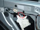
tailgate lock release cable 217 views
|
|
tailgate lock release cable23 views
|
|
54 views
|
|
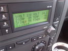
Voltage Display Page Radio Head Unit 118 14.2840 viewsThis shows the voltage/temperature/timer display page within the 6CD-465 radio head. There is a second file within this album, a doc file, that outlines the procedure to access the diagnostics.
The 14.1 volts number was the approximate vehicle system voltage with the engine running; the 118 number infers 11.8 volts which is the low power infotainment system shutdown cutoff voltage. The factory default setting is 135 or about 13.5 volts. By holding the keypad 1 button down, the 3 digit volts numbers will decrease 001 at a time until the keypad 1 button is released. Decreasing the number from 135 to some lower number should increase the time the system will remain on with the engine off.
The TEMP numbers refer to Fuel Burning Heater, (FBH), temperature values. 85 is apparently a high limit and 46 was the number when the jpg was taken. This number varies and given that there is no diesel fueled FBH in our NAS petrol engine vehicles, what the value refers to is unclear. The TIMER numbers also relate to the diesel fuel burning engine heater and perhaps make more sense being 00.
|
|

Thread upload3 viewsImage uploaded in new thread
|
|
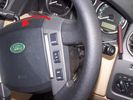
20 viewsThe Airbag will release and can be pulled towards you gently.
|
|
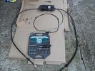
384 viewsOverview - box, two brake cables and release cable
|
|
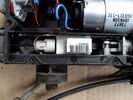
Release cable...364 views...passes round the pulley on the left...
|
|
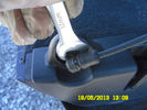
tailgate security strap release43 views
|
|
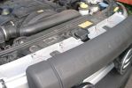
Front Grill Removal405 views
|
|
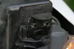
Headlamp Released314 views
|
|
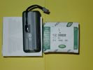
Upper Hatch Release Switch LR Part Number YUZ500020675 viewsThis is the Range Rover Sport switch, Land Rover part number YUZ500020, as it comes out of the box. Note the JAE, (Japanese Aviation Electronics), male wiring connector installed on the end of the power lead.
The rubber cover of the switch is sealed to the plastic body of the switch whereas in the previous switch design, there was no sealing. Also the replaced switch was hard wired into the same harness as the license plate lights - no JAE connector in other words.
|
|

PDF of the steps to add manual emergency tailgate release cable119 views
|
|
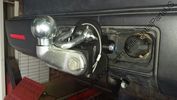
New Hitch174 viewsNew heavy duty hitch to be released for D3 LR3.
|
|
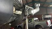
New Hitch201 viewsNew heavy duty hitch to be released for D3 LR3.
|
|

30 views
|
|
|
|