| Search results - "Line" |
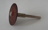
Disco abrasivo - Abrasive disc20 viewsDeclino ogni responsabilità per i danni che eventualmente farete direttamente o indirettamente seguendo questi consigli.
Per aprire la chiave ho usato un disco abrasivo da modellismo montato su un minitrapano. Deve giare velocemente.
Decline all responsibility for any damage that may directly or indirectly do by following these tips.
To open the key I used an abrasive disc mounted on a mini-drill. It must turn quickly.
|
|
138 views
|
|
Wating in line42 views
|
|
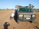
08 D3 stranded with a seized smoking wheel315 viewsAbout 1 hr after replacing the blown tyre, strange noises emanated from the stability control system and speed dropped off. Then I looked in the rear view mirror, and noted a cloud of dust along with a whiff of black smoke. This led to a very quick stop (no traffic on this route for over a week, so no worries about having to signal exiting the road). Took a look and WOW. The right rear wheel was glowing a dull red colour, and burning rubber smoke was wafting from the red glow over the fuel lines.
|
|
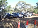
Start of Round 2188 viewsLined up with some of the Class B entries
|
|
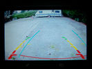
Red and yellow lines on fixed on the camera, blue lines gvif and adjustable78 views
|
|

10forcash new D3 going down the production line.308 views
|
|

up date 10forcash new D3 going down the production line.352 views
|
|
Thread upload322 viewsImage uploaded in thread 102519
|
|
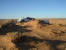
The French Line - Simpson Desert78 views
|
|

The French Line seems never ending82 views
|
|
Do Not Park Trucks On Railway Lines!182 views
|
|

This is a normal H7 HID bulb installed in a BMW headlight to show glare above cut off line99 viewsThis is what the light pattern is that causes glare in most retofit applications including some projector lights. this is in fact a projector headlight on a BMW but the old projectors were only actually half projectors and half reflective bowls. the beam pattern should be clean cut like this ___/
|
|
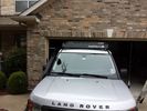
low profile solar panel211 viewsThe low profile solar panel, can be seen here, as the fine white line under the light bar. The way it's laid out, the panel should generate decent power between 10am and 4pm depending on the time of year, from the sides or front, with no shadows. Grape Solar 100W flex panel.
https://www.facebook.com/DifferentialPartsUS
|
|
D3 HighLine 6CD_CopyCD Stuck29 views
|
|
what a line up63 views
|
|
D3 LowLine 1CD/Tuner33 views
|
|

30 views
|
|

2 Maintenance Schedules - Gasoline Engines17 views2 Maintenance Schedules - Gasoline Engines
|
|
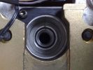
3 Splines and alignment mark44 views
|
|

D3 line up at Peterborough 08173 views
|
|
Descending through the tree line53 views
|
|

Entertainment System Wiring Diagrams2331 viewsThe 12 page pdf has the wiring diagrams for the low and high line "radio" and various components such as the amplifier, phone modules,NAV display, antennas and satellite radio and TV.
|
|
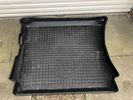
Boot liner10 views
|
|
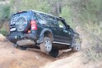
The Powerline Track - Perth218 views
|
|
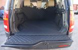
Thread upload1 viewsImage uploaded in new thread
|
|

5 Driveline11 views5 Driveline
|
|

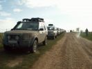
Line up of LR\'s (ignore the Toyota at the end :-()162 views
|
|
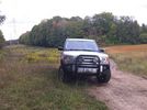
Ooops, found the mountain bike trail. KW Hydrocut16 viewswe were out one day and suddenly I seemed to recognize the power lines, and the fact that the mountain bike trail runs alongside the lines.
This is obviously a wide section of trail, but it's still the KW Hydrocut mountain bike trail.
|
|
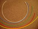
6mm Heat Shrink colours 362 viewsI decided to colour code the tubing so I used 6mm electrical heat shrink.
As there is no apparent colour coding re the 3, I tried to emulate the P38 coding; #1 LR red, #2 RR blue, #3 LF yellow, and #4 RF green. This was not doable as both left side air springs have green coloured tubing coming off the top of the front and rear air springs. I therefore arbitrarily chose the Left Rear to be red; Left Front green; Right Front yellow; Right Rear blue; and for the air compressor supply line, White coloured heat shrink. Since two new lines tie into each air spring line, I made the line between the air spring and the FASKIT, a single solid colour, and the line from the FASKIT to the valve block, White, plus the related appropriate solid colour.
|
|
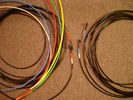
6mm PA12 grade nylon tubing with heat shrink applied 544 viewsShows some of the 6mm air line with heat shrink applied to one end of tubing. Shrink will be applied to the other end once field cut to length. These four tubes, each about 20 ft (6m) long, feed to the rear. Re the front air lines, (not shown), four additional lengths, each about 10 ft (3m) long, are required plus one more 3 metre length for compressor air. The 6mm tubing is a Nylon product specified as PA12. There is also a very similar Transport grade PA11 material, however it seems that PA12 is the more common Transport grade now in use. Also the applicable DIN standard seems to be both DIN 73378 and DIN 74324 for the nylon tubing. The working pressure of the 6mm tubing is about 27 Bar and bursting 82 Bar @ 20C. This is for the 1mm nominal wall thickness material, (4mm ID, 6mm OD).
|
|
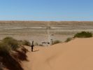
QAA Line - Simpson Desert79 views
|
|

French Line - Simpson Desert near \'Lake\' Thomas115 views
|
|

130 viewsThis is the installation guide from the manufacturer
|
|

Thread upload55 viewsImage uploaded in thread 169001
|
|
Thread upload5 viewsImage uploaded in new thread
|
|

Amplifier wiring98 viewsChanges for converting High Line to Premium.
|
|

Thread upload9 viewsImage uploaded in new thread
|
|
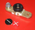
Battery Disconnect side post with + & - caps, top view617 viewsThis disconnect is designed for side post batteries. It can be used on either the + or - terminals. It can also be installed at the "other" end of the battery cable as well. In my install of the Aux battery, I installed this on the negative ground cable where the cable attaches to the body sheet metal. I have never used it but it seemed like a good idea at the time. The main battery hookup is pure stock.
For the hot side of the Aux battery, an Anderson PowerPole was used inline for the cable between the Aux and connecting to the spare bolt hole at the + post of the Main battery cable.
|
|

36 views
|
|

114 views
|
|

Thread upload17 viewsImage uploaded in thread 126921
|
|
Thread upload0 viewsImage uploaded in thread 123869
|
|
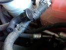
Breather line with factory cap cut off.2320 viewsIf you expand the jpg by clicking on it, in the bottom right corner if you look closely, one can see the black plastic factory vent tubing with the OEM cap cut off.
Note the tubing is cut at a 45 degree angle facing to the rear. Also shown in the top right is the cut off portion sitting on the coolant water hose and on the top left also sitting on the coolant hose, the new to be installed Gore manufactured replacement breather cap.
|
|
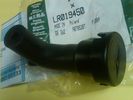
Breather Cap part # LR0194501541 viewsThis is the replacement breather cap as manufactured by the Gore Tex people, (Gore), for the engine compartment end of the front differential breather line.
You can with some difficulty, both blow and suck thru the breather filter material. The Gore Tex filter material has what are called hydrophobic and oleophobic properties. This means the filter material keeps oil in and water out, while at the same time, allowing air pressure to slowly equalize, (air permeable). Additionally, the transfer of dust, salt, and road debris is inhibited.
|
|
91 views
|
|

Thread upload22 viewsImage uploaded in thread 161370
|
|

74 viewsMS excel sheet for monthly mileage report will give average fuel consumption.(most cells have formulas to help fill in from previous line)
on first sheet add details you want on monthly sheets. during use the data needed to be added is ending reading on clock, places visited (if you want).
how much fuel when you purchased it also fuel in tank at start and end of month
|
|

RHS view371 viewsSHows the Front Runner (SA) slimline windcheetah rack which is immensely strong. Takes my 110kg (oh gawd, I must get back on the diet and exercise regime) tramping over it when loading/unloading gear without a problem. Fittings are simply fixed or removed, and IMO very well designed and made. IPF 800 series driving and spots fitted to the front of the rack. IPF cam/reversing fitted each side and to rear of rack for negotiating rocky wadis at night. The G4 stickers were bought off E-bay as a set.
|
|
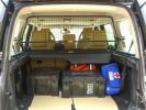
Load space368 viewsShows the SA Front Runner Wolfpack stacking plastic storage boxes that I keep laod straps etc in and the 2nd is tool kit, spare belts, jerry can funnel and tools, plus airline and tyre inflator/deflaotr for ARB on-board compressor, HD jump leads. ARB Winch pack (Orange)with strops, snatch blocks, shackles, gloves, and 2 ARB recovery dampers. Really great 4x4 1st Aid kit from Outdoors warehouse in SA. LRs own loadspace guard - not the best design if you want to store a long load. Mods to be carried out!
|
|

Thread upload26 viewsImage uploaded in new thread
|
|

Cooling system hoses - 4.4L petrol V81109 viewsThese are the cooling system hoses on the 4.4L petrol V8. The little odd shaped bleeder hose, (LR006158), shown in the top right hand corner can give problems. There is a plastic tee with a threaded air bleeder outlet located in the middle of the hose. The plastic tee can or will fail due to I guess heat distress.
A BIC pen can serve as a field fix, however for your parts kit, a nominal 3/8" ID hose size brass hose barb inline connector plus a couple of hose clamps is suggested. Better yet is a threaded hose barb brass coupling or a tee and bleeder valve to allow bleeding of the line. Land Rover now makes the plastic bleeder valve that breaks available as a separate part, # LR027661, where 0 is a zero. As such, one can now purchase that part only for addition to your field fix parts kit.
|
|
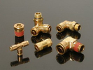
Detroit Fluid DOT air line fittings718 viewsThe picture shows the internal ferrule that is characteristic of the DOT / TUV accepted fittings for highway vehicles. Most often these fittings are metal however the Land Rover John Guest 6mm straight connector is all plastic and has the internal ferrule.
|
|
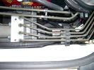
CounterAct Power supply mounted under brake lines.194 viewsThis top view shows where I located the power supply. It is attached with 3M sticky to the black plastic surface that is located under the brake lines.
When the system is operating properly, the red LED pulses about twice per second.
Some users claim they can hear a very slight hum or whine coming from the unit. My unit seems silent.
|
|
Thread upload1 viewsImage uploaded in new thread
|
|

line up60 views
|
|
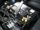
2nd battery in engine bay. Look under the rigid brake lines to see the solenoid438 views
|
|
Mrs JMC poses with the D3 line-up238 views
|
|
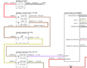
Thread upload28 viewsImage uploaded in thread 110993
|
|
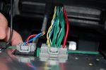
D4 LOW LINE DVD PLAYER CONNECTIONS75 views
|
|

26 viewsThe iconic finish line - driving through Tiananmen Square in Beijing, China, at the end of a dramatic 8,000-mile of the Land Rover Journey of Discovery.Courtesy of Interactive Land Rover MENA's FB page
|
|

78 views
|
|
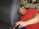
arm rest fit213 viewsthis is gary from trim-line... a job he knows to well as he is in landrover dealers most weeks..
|
|

TRIMLINE SYSTEMS what can i say.... 119 viewsThank you Gary from trimline
|
|
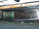
Defender32 viewsTrailAir reverse image with distance and hitch guidelines.
|
|
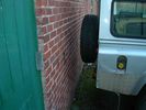
Defender 25 viewsReverse using TrailAir camera guideline
|
|
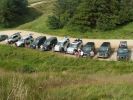
Derbyshire Bridge Line Up175 viewsTime for a brew at the end of an excellent day
|
|

415-03 Audio System - Low and High Line Radios934 viewsThis 8 page pdf shows both the low and high line radios and their various components.
|
|

419-08 Low and High line radio systems components and operation838 viewsThis 15 page pdf displays the radio components including pinouts for both the low and high line head units and the two Harman Kardon amplifiers including the Logic 7 amp. The steering wheel controls for both the radio and phone system are also outlined along with mention of the Sirius satellite radio feature.
|
|

41 views
|
|
Thread upload6 viewsImage uploaded in new thread
|
|

Thread upload6 viewsImage uploaded in new thread
|
|

Thread upload1 viewsImage uploaded in new thread
|
|
Thread upload3 viewsImage uploaded in new thread
|
|
Thread upload4 viewsImage uploaded in new thread
|
|
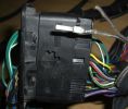
New Speaker Cables.111 viewsThis is the door connector, Main loom to Right, Door side to the left. to the top of the connectors you can see green and Green white wires which are the speaker ones. The door wiring is premium and has two pairs, the main loom was a 1 pair high line, so i am adding the pair you see (one already pinned up) to upgrade the loom to premium.
|
|

BUCYRUS117 viewsActually been in one of these monsters at Allerton ByWater open cast before it shut
Stefan Frankowiak and Darren Axe and Martin Roberts
|
|

Draper air jack258 viewsDraper air jack, stock no. 61432, part no. AJ3 at http://www.drapertools-online.com/b2c/b2citmdsp.pgm?pp_skmno=61432
|
|

11 views
|
|
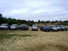
The line up422 views
|
|
Tim, DSL & Zaphod at Lochearnhead152 viewsOn the old railway line
|
|
The start line323 views
|
|
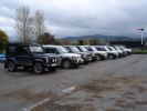
Line Up at Bala409 views
|
|

Line Up at the dam470 views
|
|

86 viewsLHS rear wheel well, with inner guard off. The rear AC lines (assuming you have an HSE) don\'t run in same way as the RHS, so on all cars, you can fold the red line inboard, with the bend roughly at the blue line, so that the very rare contact with larger tyres is eliminated.
|
|

Pauline in G4178 views
|
|
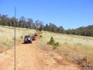
line up the hill183 views
|
|
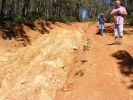
checking out the back fence line track200 views
|
|

Waiting in line63 views
|
|
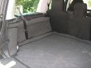
Over The Top load liner176 views
|
|
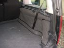
Over The Top load liner175 views
|
|
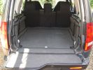
Over The Top Load Space Liner190 views
|
|
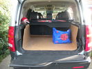
boot 21st June 2011196 viewsHand made boot liner, works a treat!!
|
|
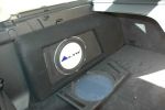
10 inch very narrow sub Phase linear Alto..now you see it460 views
|
|

First Discovey 3 off the line (US Spec LR3)424 views
|
|

First Discovey 3 off the line (US Spec LR3)382 views
|
|

First Discovey 3 off the line (US Spec LR3)450 views
|
|
First Discovey 3 off the line (US Spec LR3)621 views
|
|

25 views
|
|

Thread upload5 viewsImage uploaded in thread 137807
|
|

Mundaring powerlines 249 views
|
|

mundaring powerlines 147 views
|
|

The smell of Adreneline308 views
|
|
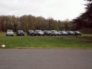
View from the Fairmile Carpark of 9 members cars198 viewsRange Rover Au Poivre had turned up by now - VA was having seat as well as steak sauce problems! I think we had 2 more turn up after this photo was taken
|
|
Line Up49 views
|
|
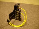
FASKIT on end view 864 viewsEnd and rear view of the FASKIT. Yellow lines are as shipped for hooking to the air supply; one line to valve/filler and other is to gauge. I will modify the arrangement to delete one of the yellow lines such that gauge line plugs into where the second yellow line is right now,(will be only one yellow tube), and then the air source line will plug into the port controlled by the valve, (hidden in this view but visible in other view). When white valve is in the ON position, gauge will read air source pressure, and be available to supply air to any of the selected four air springs. When valve is closed, the gauge will show individual air pressure in each of the air springs when a jumper is run between the gauge Schrader valve and the appropriate air spring Schrader valve.
|
|

Thread upload2 viewsImage uploaded in new thread
|
|

Hi Line antenna locations30 views
|
|

various 4x4\'s on fraser island184 views
|
|
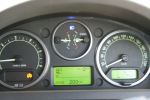
French Line - On the road. Minus 6 earlier270 views
|
|

Fuel lines post MY 07201 views
|
|

fuel tank and fuel lines43 views
|
|

276 views
|
|
Thread upload4 viewsImage uploaded in thread 187332
|
|

23 views
|
|

Thread upload5 viewsImage uploaded in thread 196952
|
|

Fuel_tank_and_Lines.pdf41 views
|
|

Thread upload33 viewsImage uploaded in thread 117618
|
|

Thread upload26 viewsImage uploaded in thread 117618
|
|

Newspaper Headlines19 views
|
|

Oil specifications for land Rover models198 views
|
|

Thread upload13 viewsImage uploaded in thread 65718
|
|
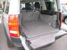
Discovery 3 boot liner from www.hatchbag.co.uk396 views
|
|

Rear heater line relocation191 views
|
|
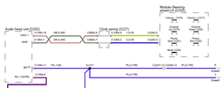
High-line stereo43 views
|
|

LR4 2012MY High line Premium audio62 views
|
|

47 views
|
|

Usefull pic for many threads posted on here. Please feel free to use! 75 views
|
|

Check the Snow Line ...171 views
|
|

Check the Snow Line ...177 views
|
|

FL2 MOST Bluetooth Instalation Instructions97 views
|
|
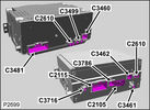
Base model IHU and High line IAM module connections83 views
|
|

Main Liner with Rear Plus6 views
|
|
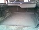
Butyl Pond Liner - Boot Floor Protection215 views
|
|
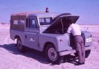
End of the line at Ras Al Khaimar72 viewsI am led to believe that this example was left overnight on the beach broken down - by morning the natives had stripped every last piece of usefull equipment out of it, engine and all and dragged it across the creek back to their village
|
|

AutoEnginuity ProLine VCI19 views
|
|

Inline power meter22 views
|
|

Grrrr, Air Line Hoses21 views
|
|
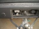
12volt 250amp power outlet, PCL airline outlet396 views
|
|
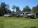
Rest stop after our first hill descent - line of cars stretched way back up the hill that disappears up to right of photo.201 views
|
|

Last D3 through the deep crossing229 viewsThe water was stirred up by this time (didn't start off too clean due to heavy rains in the previous week) water was between 500 and 600mm deep depending on where the driver crossed. Away from the tree was slightly deeper but most drivers chose that line to be well clear of the tree.
|
|
3M "Thingies" x 2187 viewsI\'ve since stuck two together in-line but the method behind the madness is the same. The blinds now don\'t randomly BANG open.
|
|
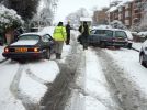
Snow, London, unfortunately for them they couldn't make the small slippery incline, fortunately for me I was in a D3....300 views
|
|
LQ04 - Andy in tree-lined corridor152 views
|
|

Waiting in line210 viewsI can\'t wait for my turn...
|
|

Angus coastline22 viewsTrying out Disco for the first time offroad
|
|

The Line Up43 views
|
|
New line in Carbon Fibre Grill36 views
|
|
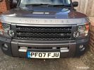
New line in Carbon Fibre Grill38 views
|
|
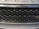
New line in Carbon Fibre Grill39 views
|
|
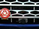
Cabled winch control connector115 viewsAdditional angle bracket made for connector in aluminium attached to red grill. Additional in-line connector between this and the solenoids to allow rad grill to be removed when required.
|
|
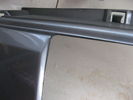
107 viewsexisting grille cut out along rib/line
|
|

Openreach Line Test 223 views
|
|

Openreach Line Test23 views
|
|

Line up29 views
|
|

D3 Rear Tailgate switch headliner connector8 viewsThe black connector in the headliner of a D3, showing the brown wire being pushed back and not making contact, and stopping the rear button from working
|
|

line up51 views
|
|

CALENDAR 2008 ENTRY - Sunset over the Alps770 viewsCALENDAR 2008 ENTRY
Drove to the top of my local mountain so "the airliner" could pose for a couple of pics with the sunset drenched Swiss Alps in the background, 80km to the south.
|
|
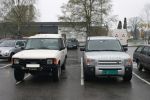
Two nice cars at the parking line 04/2005459 views
|
|
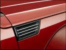
2007 Dodge Nitro - where did they get that design cue from?256 views
|
|

2007 Dodge Nitro244 views
|
|

Base mounted on Expo Rack lined with non slip mat 73 views
|
|
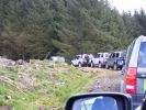
Disco Line Up63 views
|
|

Discovery Line up Kielder61 views
|
|
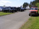
Line up Kielder63 views
|
|

Freelander 2 on the start line302 views
|
|

Thread upload14 viewsImage uploaded in new thread
|
|
86 views
|
|
98 views
|
|
99 views
|
|

Thread upload1 viewsImage uploaded in thread 183644
|
|
332 views
|
|
289 views
|
|
221 views
|
|

79 views
|
|

72 views
|
|

72 views
|
|
Thread upload19 viewsImage uploaded in thread 132482
|
|

DSL Packet Loss30 views
|
|

lin up26 views
|
|
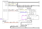
Low-line stereo47 views
|
|

45 views
|
|
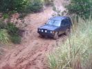
Clay incline87 views
|
|
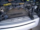
19mm wiring loom in trough behind bumper and in front of rad792 viewsThe 19mm wiring loom is large enough that a maximum of six 6mm air lines can be fished thru as required. The loom runs from the FASKIT panel located in the engine compartment behind the left front headlight, down and across in front of the rad and then down to the front axle valve block located behind and below the right fog light.
|
|
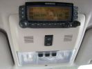
388 viewsCompleted Install of Control Panel. Wiring goes up into headliner, over curtain airbag on left hand side, and down the B pillar.
|
|

Battery Maintainer pigtail sticking out of Grill728 viewsThis is all you see when everything is put back together - just the pigtail and Weather Pack blanking plug. Most often, I have it all tucked back behind the grill.
In winter, there may be a second cord hanging out as well - the 120 VAC power cord for the engine block heater, a tea kettle like element inserted in the engine block. NAS petrol V8's do not have the Fuel Burning Heater, (FBH), installed, but instead in cold area markets have the block heater element assembly available as a dealer installed option. There is an argument to say that the heating element is factory installed in all cold climate V8 gasoline engines, however the appropriate power cord is not. If true, this means that all one needs to purchase is the area specific power cord and plugging in / attachment to the engine block located block heater.
As such, you will often see a conventional 120VAC three prong power plug hanging loose out of the grill of most vehicles here in the wintertime. In summer, most drivers tuck the plug back behind the grill as it is no beauty mark.
|
|
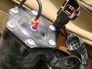
Compressor Electrical Plugs 1406 viewsThis shows the two electrical connectors; the two pronger is the power to the compressor, and the multi-pin connector carries control signals. Also the temporary red plug is where the 6 mm tubing from the centre valve block connects. This line carries both the compressor and exhaust air to and from the springs.
|
|
Compressor Exhaust and Inlet 1534 viewsThe two temporary black plugs cover off the 8mm and 10mm push fit lines to the air inlet and exhaust lines. Also visible is the worn threaded stud that I think was the initial failure mode.
|
|
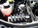
View of mounted panel from front left side878 viewsNote that all valve handles are shown in the OFF position, (the trouble position). In this case, the air that is in the air springs, (if any), is trapped in there - that is the valve blocks cannot vent whatever air is already in the air springs as the air lines between the springs and respective valve blocks are closed off by the FASKIT valves. In operation, there may be only trouble with one air spring, (perhaps a wheel height sensor), and as such, only one valve would need to be closed. If there was complete air compressor failure, then all valves would be closed and then as required, each spring could be manually filled from an outside clean dry oil free air source.
|
|
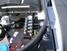
View from front left side looking towards rear aux battery compartment under cover 647 viewsAs there is no Fuel Burning Heater in the NAS V8 petrol vehicles, there is space available to install the FASKIT panel here. The piping is such that each air spring can be isolated from the air system and then filled one at a time manually via the Schrader valve. There are five Schrader valves and five shutoff valves. The fifth valve nearest the gauge controls air from the compressor, and can provide fill up air via a jumper fill line assuming the compressor is still operational.
|
|
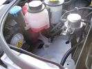
Empty space in NAS LR3 for location of FASKIT panel599 viewsThe empty space is available as the North America Spec gasoline engine LR3's do not have the Fuel Burning Heater installed. The air lines from the four air springs and the air tank will appear to rise up from under the headlight assembly. The lines to the front block valve assembly located behind the front right fog light will sort of run within the bumper across the front of the radiator down into behind the righthand fog light. The rear lines somewhat follow the path of the existing air feed line from the front valve assembly to compressor. Rather than be located between the left front fender liner and left metal wing however, the four lines will feed thru the empty wing space inside and above the wheel well arch and exit down by the left front mud flap. From there, the lines run along the left frame member above the air tank and then parallel the frame over top the compressor to the top of the rear left air spring where the rear air block valve assembly is located.
|
|
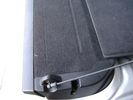
Flexible wire rope fishing leader 0.032" diameter exiting carpet 1949 viewsThis is all you see of the completed mod.
The short little angled "line" about an inch long that looks like a piece of debris and is located a few inches "above" the support cable is actually the wire rope release cable exiting from under the carpeted lift gate cover.
I drilled a very small hole in the carpet and pushed the 0.032" diameter release wire thru and then slipped the loose end under the black plastic.
To release with the lift gate etc closed, from the inside, just pull the loose end free from under the black plastic and gently pull wire about 5mm, (1/4"), and the upper door catch should release. You will have to manually push the upper door out wards to actually effect opening, but you will already be inside the rear cargo area so that part is easy to do.
The assumption is that the lower door latch still works electrically and hence, the lower lift gate half will open as normal by pressing the usual button on the top left of the lower door half.
|
|

NAS 7 Blade Round plus NAS 4 Pin Flat Vehicle end Socket528 viewsThis shows the function of each blade when looking into the connector at the vehicle end for the 7 pin NAS plug. The layout is the pin order for most new North American pickup trucks and the LR3/4.
The colour and gauge of the wires feeding into the back of the plug varies even within manufacturer model lines.
Also detailed is the flat 4 pin layout common on smaller trailers not having electric brakes. This includes most U-Haul rental trailers.
|
|

LR3 Production Line 171 views
|
|

LR3 Production Line 263 views
|
|

LR3 Production Line 362 views
|
|

LR3 Production Line 458 views
|
|

LR3 Production Line 360 views
|
|

LR3 Production Line 657 views
|
|

Wheel cut thru definitions and specs898 viewsNote the location of REAR SPACING and also OFFSET; probably two of the most important dimensions and not always understood as related to wheel size and relationship to the brake components.
For the 3, Rear Spacing is approximately 6.5 inches or 165 mm for a nominal 8" rim. Offset is 53P or 53mm Positive, which means the distance from the machined hub flat mounting surface to the rim's true centreline is 53 mm in the outboard direction. (The rim illustrated has a negative offset.)
As Positive offset increases, this means the wheel wraps around the disc brake mechanism more deeply, and hence the more the wheel would cover the brake parts. This is why most 18" wheels will not fit with the larger Brembo "supercharged engine" brake calipers.
Pitch circle diameter is 120mm; Pattern is 5 lug, and the tyre load rating is 112 with a recommended tyre speed rating of H or higher along with the XL load rating. For the 3, the stock tyre diameter is about 30 inches. The 255/60/18 or 255/55/19 OEM tyre outside diameter is 30.04 inches; Wheel lug torque is from 130 to 150 Nm or 96 to 110 lbf-ft and the lug nut hex socket size is 22mm.
Max Load High Speed Driving Tyre pressures are Front, 33 psig, (230 Kpa) and Rear, 42 psig, (290 Kpa).
The OEM rims are rated at 940 kgs, the highest that LR makes, hence while rims from other Land Rover products may physically fit, the odds are they are under rated in a weight sense.
|
|

Underhood Fuse and Relay Box drawing 3055 viewsShows the various fuse and relay locations. Fuse 3E, (5 amp), and Fuse 26E, (20 amp), as well as upgraded 70 amp Relay 7, part number YWB500220, locations are displayed. Relay 7 sends battery power to the compressor from the 60 amp fusible link called up as 10E. Fuse 26E is what provides full time always on battery power to the air suspension ECU and hence powers the auto level wakeup when the vehicle is shut down and say parked for the night. Removing F26E is the primary method to disable the air suspension system; Removing F35P is more if you want to experiment with it from inside.
I found it useful when I had a suspension problem, (actually a wheel alignment problem picked up by the steering wheel angle sensor), that only showed itself on the highway but allowed for no trouble light driving in the city. This was because in the city, the steering wheel was always in motion and rarely was the vehicle driven in a near straight line for very much distance.
|
|
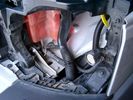
19 mm wire, (tubing), loom rising from below at left headlight657 viewsFrom the FASKIT panel, five air lines fit in the 3/4" (19mm) wiring loom and feed to the front air valve block located behind and under the right front fog light.
|
|
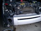
Wiring, (tubing), loom exiting temporarily from the front right fog light.569 viewsThe front axle air valve block is located just behind and below the fog light. Access to the valve block is by removing the right front fender liner, (or the bumper). The FASKIT lines are attached to the left and right front air spring lines at this location; also compressor air is taken from this location as well. Cutting the lines at as few different locations makes it easier to find leaks at a later date. As above, five 6mm air lines run from the FASKIT panel to the front axle air valve assembly and run within the loom. Two pair of the lines are for control of the air springs, and the fifth line taps the air supply at the valve block assembly off the compressor. This will be the air source line rather than tapping in directly to the high pressure air tank.
|
|

LR3 Air Conditioning High Line electrical wiring diagrams1466 viewsThis 7 page pdf shows the wiring for the Heater/AC both front and rear.
|
|
Thread upload16 viewsImage uploaded in thread 123540
|
|

Excel file for Rotors and Brake Pads part numbers for 4.4L V8 petrol LR3769 viewsComparing the cost of the various brands of brake parts is time consuming. Once you have your parts costs, this little spreadsheet will make collating the info easier.
I did not make any provision for labour costs, but the file can be downloaded and then modified. You can change Dollars to Euros or Pounds or whatever and insert lines for labour costs as desired.
Do not pay too much attention to the $ numbers as they are a mix of US and CDN, and from differing time frames, (prior to Spring 2011) . Also the brake part numbers are for my 2005 North America spec LR3 with the petrol 4.4L V8; diesel powered and supercharged 3's may have different part numbers
|
|

Thread upload14 viewsImage uploaded in thread 149931
|
|

LTB00102 - Technical Bulletin - Driveline Clonk Noise after Throttle Release Reapply - Repair Procedure97 views
|
|

LTB00345 - Technical Bulletin - Headliner Delaminating Around Roof Opening Aperture89 views
|
|

Lug Nut part number RRD500290 outline sketch541 viewsThis single sheet pdf provides dimensions of the LR part number RRD500290 lug nut on vehicles from MY 2005 to 2008, (up to VIN 8A450459). From VIN 8A450460, the part number is RRD500590.
Visually, there is no apparent difference between the two part numbers. The dimensions appear identical as well. The shape, size, and profile of the Stainless Steel "hat" appears identical.
There are I presume differences in metallurgy to reduce corrosion and swelling of the hat or perhaps better sealing between the inside surface of the hat and the steel of the lug nut body. The reality is the differences are not immediately obvious however.
A 22 mm six point half inch or larger socket drive fits over the lug nuts. I use a nominal 36" long breaker bar with the 22mm socket - any shorter bar, best you be in shape. Depending upon your source, for both alloy and steel wheels, the lug nut torque value appears to be 103 lbf ft, (140 Nm); others suggest first tighten to 96 and then finish at 110 lbf ft, (130 and 150 Nm).
|
|

Thread upload15 viewsImage uploaded in thread 188003
|
|
104 views
|
|
Thread upload3 viewsImage uploaded in new thread
|
|
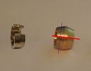
4 viewsI modified a compression fitting collet (right) to match a Landrover voss fitting collet (left) by cutting at the lines as shown. Intended as a temporary fix for a leaking voss fitting, but has worked great for several years.
|
|

31 views
|
|

New Discovery 4 SDV6 at dealership awaiting collection78 views
|
|

11 views
|
|
wheelarchliner257 views
|
|

wheelarchliner159 views
|
|

Trip to Tassie494 viewsWaiting in line to board the Spirit of Tasmania at Darling Harbour, Sydney.
|
|
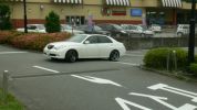
Unknown Make197 viewsSnapped as it was leaving a small shopping centre but particularly interesting swage lines over the wheels which are featuring the typical Japanese feature of ultra low profile tyres. Ugly as a hatfull treatment of the front end though.
|
|
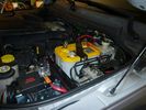
Traxide SC80-LR mounted713 viewsIn this position it fits properly without stress or stretching the plastic. A single small bolt holds it securely in place, and not toughing or rubbing on wires or suspension air lines.
|
|
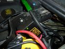
Traxide SC80-LR mounted598 viewsA close up showing the angle, mounting bolt. Only a single top bolt can be used, there are metal lines behind the lower bolt hole.
|
|

Broom's Head96 viewsBroom's Head is a delightful surf and still water area south of Yamba on the noth coast of New South wales.
In this photo looking south a pod of dolphins were playing in the first line of breakers.
|
|

Vista struttura ospitante e colline205 views
|
|
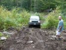
Starting Line217 views
|
|
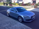
Previous Motor86 views07 Audi TT 200BHP S-Line
|
|
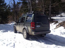
Killington, VT37 viewsParked on upper driveway, the driveway was covered with 6 inches of snow and the incline was at least 30 degrees and the LR3 made it up with no problems.
|
|

What a line up!696 views
|
|
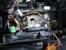
219 viewsThe inner workings of the floor console. You can see the inline fuse holder on the left, which then connects to the chill box connector.
|
|
88 views
|
|

Final Lineup78 views
|
|

Thread upload3 viewsImage uploaded in thread 144213
|
|

On top of Big Red - the real crossing297 views
|
|

The French Line looking west205 views
|
|
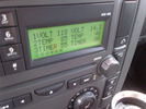
Voltage Display Page Radio Head Unit 118 14.2840 viewsThis shows the voltage/temperature/timer display page within the 6CD-465 radio head. There is a second file within this album, a doc file, that outlines the procedure to access the diagnostics.
The 14.1 volts number was the approximate vehicle system voltage with the engine running; the 118 number infers 11.8 volts which is the low power infotainment system shutdown cutoff voltage. The factory default setting is 135 or about 13.5 volts. By holding the keypad 1 button down, the 3 digit volts numbers will decrease 001 at a time until the keypad 1 button is released. Decreasing the number from 135 to some lower number should increase the time the system will remain on with the engine off.
The TEMP numbers refer to Fuel Burning Heater, (FBH), temperature values. 85 is apparently a high limit and 46 was the number when the jpg was taken. This number varies and given that there is no diesel fueled FBH in our NAS petrol engine vehicles, what the value refers to is unclear. The TIMER numbers also relate to the diesel fuel burning engine heater and perhaps make more sense being 00.
|
|

Radio Head 6CD-465 Display diagnostics and low power procedure757 viewsThe one page doc outlines the procedure to access the diagnostics for the 6CD-465 entertainment system in most of our LR3's.
|
|
Thread upload13 viewsImage uploaded in new thread
|
|

Stuff115 views
|
|
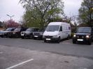
D3 line up at the Red Lion in High Lane164 viewsAndrewS\'s Merceds Sprinter Van (fastest vehicle on the road) spoils the line-up in the car park
|
|

74 views
|
|

Thread upload14 viewsImage uploaded in new thread
|
|
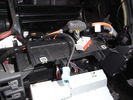
Hi Line stereo on its way out...23 views
|
|

Hi Line stereo with plugs still in place14 views
|
|
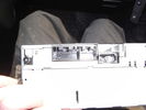
Rear of Hi Line stereo with plugs removed17 views
|
|
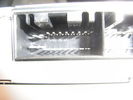
20 pin socket on rear of Hi Line stereo14 views
|
|
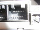
12 pin Aux socket on rear of Hi Line Stereo11 views
|
|
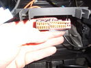
Hi Line stereo plugs with radio removed. Aux plug on the left14 views
|
|
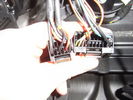
Plugs removed from Hi Line Stereo 'as they hang out' of the dash15 views
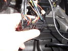
|
|
Plugs from rear of Hi Line stereo 'as they hang out' of the dash15 views
|
|

At the beach464 viewsInstalled the rails to bring home the Christmas tree. Installed them myself & quite proud of that fact since I\'m not the mechanically inclined type hehe.
|
|
Group 2 - Lead by me!208 viewsHaving finally got free of the Roych we stopped for a photo opportunity - like you do!
|
|

Thread upload19 viewsImage uploaded in thread 158227
|
|
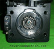
NAS 7 pin + NAS 4 pin Flat Trailer Socket308 viewsThis is the vehicle end of the NAS trailer harness that is located behind the removable plate centered within the rear bumper by the towing loop. Re the four pin flat connector, from the bottom, the exposed bare lower pin is the ground, usually the White wire on a NAS trailer. The next pin up is normally a Brown wire on a trailer and is for the Tail Lights. The third pin, normally a Yellow wire, is the left signal light; the top pin, normally a Green coloured wire, is the right signal light.
Re the round connector, from the notch in the plastic surround, clockwise, the first blade is ignition controlled +12VDC battery power, (only alive when engine running), and on the Land Rover factory harness is an Orange wire; on a NAS trailer, usually Red but perhaps a Black wire.
Next blade clockwise at 3:00 o'clock above, is the Right Turn signal light, a Green wire on the LR harness, and also on a NAS trailer.
At 5:00 o'clock, the next blade is for the Electric Brakes and is Blue on both the LR harness and on a NAS trailer.
The Ground wire is next, White on both the LR harness and on a trailer.
At 9:00 o'clock above, is the Left Turn signal, Yellow on both the LR harness and on a trailer.
The last blade to the left of the line up notch is the Tail Light circuit. On the LR harness, the wire colour is Brown with two White stripes and on a NAS trailer, Brown.
The centre pin is for the Reverse Back Up lights and is Black on the LR harness and often Purple on NAS trailer wiring but can be Black also.
Note that when the socket assembly is installed on the 3, the notch in the plastic surround is on the left - that is rotated 90 degrees anticlockwise to the picture above. In other words, When installed on the 3, the 4 pin flat connector lays horizontal and is located below the round socket.
|
|

Thread upload6 viewsImage uploaded in thread 180910
|
|

Thread upload18 viewsImage uploaded in new thread
|
|
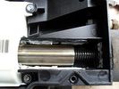
Now we are getting to it...442 views... the threaded (or DREADED) actuator - externally splined internally threaded element (centre of pic) rotated by gearbox (on left of pic) to pull cable end (externally threaded, on the right)
|
|
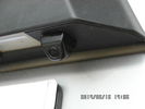
Tailgate Camera located above license plate.598 viewsThis aftermarket camera is mounted on my 2005 LR3 in almost the same location as the factory cameras. The factory units are mounted somewhat more forward closer to the metal of the tail gate and I could have done the same as well.
Note that the camera above is aimed a bit towards the centreline of the vehicle per the factory install.
|
|
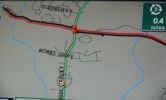
Black Line155 viewsAnyone know what the black line is?
|
|

x712 viewstight shut lines
|
|

shut up12 viewspoor shut lines
|
|
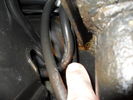
38 viewsWear to air line
|
|

Simpson July 2007124 viewsFrench Line
|
|
Calendar Entry297 views
|
|

136 views
|
|
Group 5 and others at Stonehenge144 views
|
|

Thread upload15 viewsImage uploaded in thread 187407
|
|
Thank god they lign up143 viewsCut holes are in the right place!
|
|

30 views
|
|

Thread upload25 viewsImage uploaded in thread 170139
|
|

Thread upload10 viewsImage uploaded in thread 155907
|
|

The vehicle line-up outside the Hotel in Matmata117 views
|
|

Voss B203 Fitting Install957 viewsNote on the first page, the reference to DIN 73378 and D74324 and also PA11 and PA12 material when referencing suitable spec nylon (polyamide) air line for motor vehicles. I think some of the 6mm fittings used on the 3 for the valve blocks are the System 203 type and called up as Land Rover part number RQC 000030. The Voss part number is I believe 5 2 03 11 01 00.
|
|

Voss System 203 Connector cut thru, (similar to in valve block).678 viewsThis is a cut thru of a Voss System 203 connector. The top third of it is similar to the connector that holds the three 6mm plastic tubing lines into each of the front and rear valve blocks.
I say top third, as per the other pictures, the 3 has a Voss assembly that threads into the plastic of the valve block, whereas in the cut thru above, the Voss brass assembly is threading into the brass body of a metric threaded adapter for threading into a standard type metric threaded hole. Note also the two one way sloping ridges of the cutting ring, and the two interal O ring seals that mate with the plastic tubing. There is additionally the small squashed O ring to provide a seal related to the external thread of the Voss cutting ring assembly; (similar to the larger O ring for the brass body external thread).
|
|
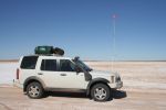
On a small salt lake on the WAA Line369 views
|
|

The team photo104 viewsTaken at the finish point - just 60 km from the nearest blacktop road! A Challenge indeed, especially as at this point fuel in 3 cars was close to the red line with 20 litres of reserve between all 5 cars!
|
|
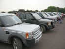
Clean line up at start136 views
|
|

Thread upload34 viewsImage uploaded in new thread
|
|
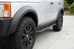
RS II Sliders129 viewsRover Specialties sliders installed (Off Roving)
type RS II slim line
|
|
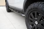
RS II slim line sliders119 viewsRover Specialties sliders installed RS II slim line (Off Roving)
|
|
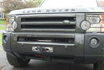
Hidden Winch Install11 viewsA front shot of my Front Runner Hidden Winch install with a Superwinch Talon 12.5 winch, D44 Hawse Fairlead, Factor 55 Flatlink Shackle, and Amsteel Blue synthetic line.
|
|
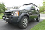
LR3 Front Shot8 viewsShot of my 2006 LR3 HSE with 18" wheels, General Grabber AT2 tires, hidden winch install, and Front Runner Slimline II Roof Rack.
|
|
|
|
|
|