| Search results - "Heater" |

Thread upload9 viewsImage uploaded in thread 193346
|
|

D3 rear 3rd row heater120 views
|
|
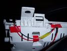
Insrument panel rear 34 viewsShowing wiring for heater and lights on indicator
|
|
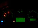
Insrument panel 36 viewsShowing heater and lights on indicator
|
|
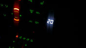
Heater Illumination35 views
|
|

Heated seats, pre-heater, heated screens. Bring it on!264 views
|
|

Air Distribution and Filtering Systems2083 viewsThis is 3 page pdf with coloured drawings of the air distribution ducting for the front air system.
Also included is a sketch of the pollen filter location within the front heater ducting. Note that two types of filters are available: a) the cheaper dust/pollen filter and b), the activated carbon filter that removes smells from the air. Installing the more expensive activated carbon filter means you never smell a cattle truck or chicken farm again. It really works.
|
|

Front Heater Doors Description and Operation1396 viewsThis 6 page pdf shows with coloured drawings the air flow thru the front heater as well as discusses the operation of the various air flow doors.
|
|

Air Conditioning and Heater Control Components2425 viewsThis is a 21 page pdf that really explains how the air system is supposed to work. Discussed are the exterior ambient air sensor, where and how it operates; the interior temperature sensor as well as humidity sensor.
|
|

Thread upload11 viewsImage uploaded in new thread
|
|
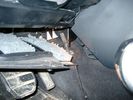
Air Conditioner Drain Hose on Drivers Side (LHD)2296 viewsThe corrugated rubber bit above and to the right of the gas pedal is the drain hose that goes down thru the carpet and floor sheet metal.
While it is bit hard to figure out from the jpg above, there is a rubber "strap" attached to the top of the corrugated hose that one uses to pull on to drag the hose up back around the black plastic heater "pan" drain. The same drain hose arrangement is on the other side as well.
One could I suppose run a plastic snap tie around the vertical pull strap if one was concerned about the hose slipping off again. See also the other jpg sketch which is from the Land Rover manual.
|
|
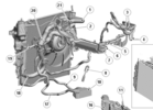
Thread upload30 viewsImage uploaded in thread 105366
|
|
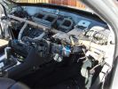
where this bit go156 viewsproject 5ser heater blower..... joy
|
|

Fuel Burning Heater Install37 views
|
|

Fuel Burning Heater35 views
|
|
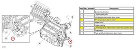
Thread upload10 viewsImage uploaded in thread 179814
|
|
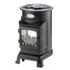
Thread upload3 viewsImage uploaded in thread 192845
|
|

357 viewsIf you look closely you can see the fuel burning heater exhausting!
|
|

B1D3445 viewsHeater
|
|

Thread upload6 viewsImage uploaded in new thread
|
|

Fuel Burning Heater Install Instructions (not mine, sorry)576 views
|
|
Thread upload20 viewsImage uploaded in thread 139852
|
|
Thread upload24 viewsImage uploaded in thread 152525
|
|

D3 Seating and Heater Mats27 views
|
|
108 views
|
|
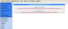
Blackbox-Soloutions Faultmate MSV2 Discovery 4 fuel burning heater test options.154 views
|
|

Stainless Steel Radio & Heater Control Covers110 views
|
|
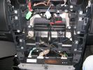
sat nav , stereo and heater missing1045 views
|
|
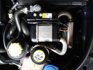
D4 FBH with heater matrix valve59 views
|
|
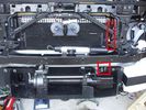
Installed winch with hydraulic hoses178 viewsThe hydraulic hoses are stiff, so I had to run them up the side of the radiator (can just see inside red boxes) to near the top of the radiator, then back down inside the engine compartment, then underneath the engine (behind the radiator) to the D4's power steering rack, where the hoses become metal. This hose routing may not be possible if the fuel-burning heater is in place (we don't have those in Aust and the space allowed room for my hands to bend and run the hoses without kinking).
|
|
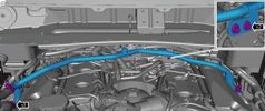
Thread upload2 viewsImage uploaded in thread 123654
|
|
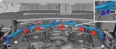
Thread upload2 viewsImage uploaded in thread 123654
|
|

503 views
|
|

120 viewsDescription & Operation FBH
|
|

FBH GSM Kit Installation Guide63 views
|
|
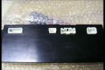
Heater Control Unit Back222 views
|
|

Heater Control Unit Front263 views
|
|
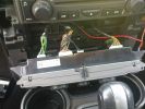
Heater control wiring138 views
|
|
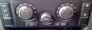
78 views
|
|

Rear heater line relocation191 views
|
|
Thread upload24 viewsImage uploaded in new thread
|
|
Thread upload13 viewsImage uploaded in new thread
|
|
Thread upload7 viewsImage uploaded in new thread
|
|

Thread upload2 viewsImage uploaded in thread 89442
|
|
Thread upload8 viewsImage uploaded in new thread
|
|

Thread upload7 viewsImage uploaded in new thread
|
|

Thread upload1 viewsImage uploaded in new thread
|
|

Thread upload1 viewsImage uploaded in thread 176300
|
|
4 views
|
|

Thread upload3 viewsImage uploaded in thread 176300
|
|
Thread upload9 viewsImage uploaded in thread 129776
|
|

55 views
|
|
Thread upload11 viewsImage uploaded in new thread
|
|

988 views
|
|

Thread upload16 viewsImage uploaded in thread 139602
|
|

windscreen fault 82 viewswindscreen damaged heater
|
|

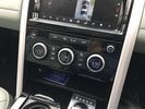
2272 viewsAll back together again, note the connector panel below the heater controls, it has USB and LAN connections for the Onboard PC
|
|

Installing a Fuel Burning HeaterTimer Remote v1-0368 views
|
|

Installing a Fuel Burning HeaterTimer Remote v1-1.pdf421 views
|
|

In car heater53 views
|
|

29 views
|
|

PARKING_HEATER_UPGRADE_KIT34 viewsHow to upgrade the water piping
|
|

Upgrade manual FBH to parking heater37 viewsManual to upgrade FBH to full parking heater functionality
Translated in English from an official German language factory manual.
|
|

Thermostat Housing LR005631538 viewsWhen the time comes to install a new thermostat, consider installing the whole housing instead.
Advantages are the thermostat is correctly installed, (not as simple as it should be); you get all new plastic and that is important, plus a new coolant temperature sensor and also a new heater coolant bypass valve, the secret part no one realizes is also within.
The cost of the whole assembly is not much more than the cost of a factory thermostat and the effort to replace all is not as difficult as it might seem.
|
|

58 views
|
|

Fule Burning Heater93 views
|
|

LR3 Air Conditioner Drain Tubes behind centre console2131 viewsThis shows the two air conditioner drain tubes located left and right under the radio stack.
The tube on the left side, (steering wheel side, LHD), disattached itself and the carpet on the floor under the gas pedal etc became soaked. I think rain water from outside that comes in the outside cowl vents also exits via the tubes as I first noticed the carpet was wet after parking outside during a big rain storm.
It was relatively easy to slide up and reattach the rubber hose that runs from the rectangular shaped plastic discharge hole(s) of the heater "pan" down along the transmission hump area and thru the floor pan. There is a hose on each side of the transmission hump, but only one hose had let go on my 3. The rubber hoses just slide over the rectangular plastic openings of the two heater housing drain outlets.
To get at each drain hose, remove the vertical sort of triangle carpeted piece below each side of the radio stack. The triangles of carpet will just pull away as each is held on with those metal U clips Land Rover so likes. Dislodge each triangle at least sufficiently to get ones hand in to slide the rubber hose back on.
You will rarely see AC water on the ground as the front drains pour onto a metal underside protection skid plate and the rear drain onto the top of the left rear muffler.
|
|

Battery Maintainer pigtail sticking out of Grill726 viewsThis is all you see when everything is put back together - just the pigtail and Weather Pack blanking plug. Most often, I have it all tucked back behind the grill.
In winter, there may be a second cord hanging out as well - the 120 VAC power cord for the engine block heater, a tea kettle like element inserted in the engine block. NAS petrol V8's do not have the Fuel Burning Heater, (FBH), installed, but instead in cold area markets have the block heater element assembly available as a dealer installed option. There is an argument to say that the heating element is factory installed in all cold climate V8 gasoline engines, however the appropriate power cord is not. If true, this means that all one needs to purchase is the area specific power cord and plugging in / attachment to the engine block located block heater.
As such, you will often see a conventional 120VAC three prong power plug hanging loose out of the grill of most vehicles here in the wintertime. In summer, most drivers tuck the plug back behind the grill as it is no beauty mark.
|
|
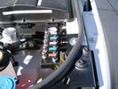
View from front left side looking towards rear aux battery compartment under cover 646 viewsAs there is no Fuel Burning Heater in the NAS V8 petrol vehicles, there is space available to install the FASKIT panel here. The piping is such that each air spring can be isolated from the air system and then filled one at a time manually via the Schrader valve. There are five Schrader valves and five shutoff valves. The fifth valve nearest the gauge controls air from the compressor, and can provide fill up air via a jumper fill line assuming the compressor is still operational.
|
|
Empty space in NAS LR3 for location of FASKIT panel599 viewsThe empty space is available as the North America Spec gasoline engine LR3's do not have the Fuel Burning Heater installed. The air lines from the four air springs and the air tank will appear to rise up from under the headlight assembly. The lines to the front block valve assembly located behind the front right fog light will sort of run within the bumper across the front of the radiator down into behind the righthand fog light. The rear lines somewhat follow the path of the existing air feed line from the front valve assembly to compressor. Rather than be located between the left front fender liner and left metal wing however, the four lines will feed thru the empty wing space inside and above the wheel well arch and exit down by the left front mud flap. From there, the lines run along the left frame member above the air tank and then parallel the frame over top the compressor to the top of the rear left air spring where the rear air block valve assembly is located.
|
|

LR3 TDV6 RRS TDV8 Engine Pre-heating Operating Instructions - Appendix343 viewsThis is the instructions you get with the LR original Webasto timer kit
|
|

LR3 AJV8 block heater location639 viewsThis 1 page pdf shows the screw in block heater location as related to the lower left side of the engine block.
|
|

LR3 Air Conditioning High Line electrical wiring diagrams1465 viewsThis 7 page pdf shows the wiring for the Heater/AC both front and rear.
|
|
Thread upload2 viewsImage uploaded in thread 198154
|
|
JK gas heater16 views
|
|

Oil Pan Heater143 views
|
|

16 viewsWindscreen heater fuses
|
|

Pollen Filter Replacement in HVAC System506 viewsThe attached single page doc includes links to pictures of the procedure to replace the "air" filter behind the passenger side glove box related to the Heater AC system.
Part numbers are provided for both Land Rover and Mann filters, both the activated carbon type and the non charcoal filters.
|
|
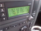
Voltage Display Page Radio Head Unit 118 14.2840 viewsThis shows the voltage/temperature/timer display page within the 6CD-465 radio head. There is a second file within this album, a doc file, that outlines the procedure to access the diagnostics.
The 14.1 volts number was the approximate vehicle system voltage with the engine running; the 118 number infers 11.8 volts which is the low power infotainment system shutdown cutoff voltage. The factory default setting is 135 or about 13.5 volts. By holding the keypad 1 button down, the 3 digit volts numbers will decrease 001 at a time until the keypad 1 button is released. Decreasing the number from 135 to some lower number should increase the time the system will remain on with the engine off.
The TEMP numbers refer to Fuel Burning Heater, (FBH), temperature values. 85 is apparently a high limit and 46 was the number when the jpg was taken. This number varies and given that there is no diesel fueled FBH in our NAS petrol engine vehicles, what the value refers to is unclear. The TIMER numbers also relate to the diesel fuel burning engine heater and perhaps make more sense being 00.
|
|
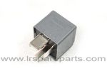
Air Compressor 70 amp replacement relay1393 viewsThere is a software update, 09 April 2010, LTB00270, for the compressor which reduces the shut down pressure to about 205 psig (14 bar). The update is usually done when changing to a new compressor and also includes replacing the R7 relay in the engine compartment fuse box, 07 DEC 2010 LTB00331.
The newer grey case coloured relay, part # YWB500220, shows to be rated at 70 amps, (the relay, not the compressor), however the previous black case coloured relay also indicates 70 amps.
Both the new and replaced relay show on their wiring diagrams to have a parallel voltage spike resistor, (probably 560 ohms), across the coil terminals, #1 and #2. This means one does not just replace the relay with any four prong 70 amp ISO sized relay that one happens upon.
One presumes the grey relay is either upgraded or just being installed for good measure. The relay is common on Ford Fiesta for the seat heater relay, Ford part number 5M5T 14B 192 EA; also Volvo, part number 30765034. The Tyco part number moulded on the grey body is V23136-J4-X62.
|
|

Seat Heater Element wiring diagram34 views
|
|
Thread upload24 viewsImage uploaded in thread 108198
|
|
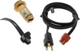
Block Heater and Cord for petrol V8 LR3 North America 120VAC529 viewsThe recommended 120VAC block heater cord is a Temro 3600003. This is a five foot long cord with what is called a Straight connector at the block heater end with holes for two pins; there is also a metal tab located between the two holes serving as the ground conductor. That cord, in addition to having the two pin holes plus ground tab end, is designed for both aluminum and brass heaters as that also matters.
The Land Rover part number for the Block Heater assembly is VUB504640 but is a Temro product not officially marketed by Temro as a Land Rover block heater. The Temro product number is 3100107 which shows as a brass body 30 mm threaded 700 watt 120VAC screw in block heater with a rectangular shaped depression and two pins suitable for the Temro 3600003 cord. Note the word BRASS as it mates with the aluminum OK.
|
|
|
|
|