| Search results - "Connector" |
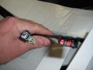
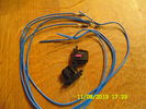
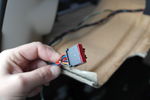
heated seat (base) wiring411 viewsThe Small connector takes the plug from the seat back pad, the larger connector (with red) is fitted into the multiplug casing uder the seat - the male side of this is already pre-wired.
|
|
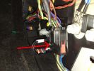
10 ICE Loom - Drivers kick ICE Loom / Dash Loom connector87 views
|
|

195 viewsCable loom with connector
|
|

Iphone in D4435 viewsIphone connector
|
|

Under seat connector - manual122 views
|
|
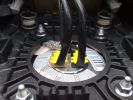
2 Airbag Connectors58 views
|
|
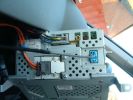
2 Dash SCREEN65 views
|
|

Drivers seat connector60 views
|
|

Drivers seat connector47 views
|
|

Drivers seat connector45 views
|
|
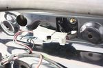
41 viewsDisconnecting the connector which gives power to the tailgate handle
|
|

usb/ipod connector 264 views
|
|

usb/ipod connector 55 views
|
|

most connector with 4 pin plug for usb/ipod module 57 views
|
|

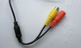
waterproof connector for connecting camera on trailer 52 views
|
|
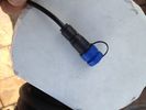
waterproof connector for connecting camera on trailer 48 views
|
|

waterproof connector for connecting camera on trailer 50 views
|
|
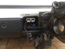
anderson connector at rear38 views
|
|

Anderson Connector setup98 views
|
|
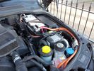
Anderson Connector setup91 views
|
|
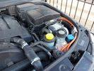
Anderson Connector setup85 views
|
|

connection the gps on the aux stereo's29 views
|
|
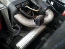
60 viewsBroken fbh connector
|
|
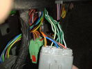
connector21 viewsLeft hand kick panel area
|
|
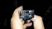
Connector on underseat harness for heated rear seats18 views
|
|
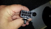
Connector from Main Loom to Heated Rear Seat Harness17 views
|
|
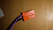
Side view of connector11 views
|
|
End of connector8 views
|
|
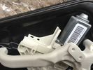
Rear window motor no grey connector11 views
|
|
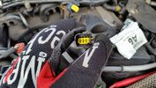
RH Glow plug connector16 views
|
|
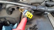
Test probe measure voltage18 viewsDo NOT insert the test probe into the connector as this can damage the terminal.
|
|
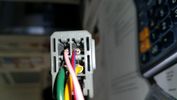
Connector 211 views
|
|
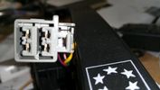
Connector5 views
|
|
Rear Power Connectors6 views
|
|
connectors97 views
|
|
connectors 2128 views
|
|
3 Dash Loom Rear of Display56 views
|
|
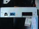
3 Navigation Bracket - nav connectors83 views
|
|
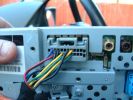
4 Dash SCREEN56 views
|
|
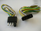
4 pin NAS flat connector from NAS small trailer381 viewsThe connector with the three exposed pins is the end that would commonly be located at the trailer hitch end, (front), of a small NAS lightweight trailer that has no electric brakes. This plug would connect into the flat 4 pin connector at the rear of the 3.
Note the order of the pin functions and wire colours: White is ground; the next pin is for tail/marker lights using the Brown wire; the Yellow conductor is for the left turn signal, and the far pin uses the Green conductor for the right turn signal.
There is no separate brake light conductor as NAS spec vehicles most often combine the brake and signal light functions to the same bulb filament rather separate filaments in different bulbs. The LR factory harness resolves that design difference.
Fortunately, the Land Rover NAS assembly pin order for the 4 pin flat plug maintains the above described conventions.
|
|

Connector C2149A20 views
|
|
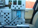
5 Dash SCREEN50 views
|
|
5 GPS Connectors GPS blue and Telephone burgandy72 views
|
|
5 ICE Loom - Location of pre fitted Voice / Speed pulse connector67 views
|
|

Thread upload48 viewsImage uploaded in new thread
|
|
6 Dash SCREEN50 views
|
|
6 ICE Loom - Voice / Telephone & speed pule connector65 views
|
|
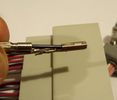
Connector sockets 8-12 & 21-2344 views
|
|

Connector: C2101101 viewsDescription: Rear control valve
Location: Below LH rear wheel arch
Part No.: YPC800230
Colour: BLACK
Cavities: 6WY
|
|
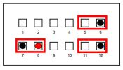
AUX Connection86 views
|
|
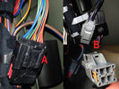
Thread upload46 viewsImage uploaded in new thread
|
|
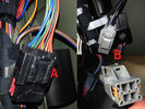
Thread upload34 viewsImage uploaded in thread 131936
|
|
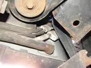
Air Conditioning Pipes (file 2)807 viewsShows location of front-to-rear air con pipes behind NS front wheel. You can just see the Vredestein tyre. The pipe connectors are tucked in behind the wheel arch inner cover. This has to be partially removed for access to bolts holding pipes together.
|
|
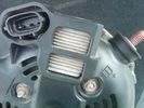
Alternator Plug and B+ terminal918 viewsPictured is the rear of the older Land Rover part # YLE500190 alternator showing the shiny cooling fin of the Regitar VRH2005-142 regulator under.
The first pin in the far left side of the connector is numbered #1 in the LR electrical wiring diagrams and is Battery Voltage Sensing (BVS); the middle pin, #2 receives a Pulse Width Modulated (PWM) signal from the Engine Control Module (ECM), and the right pin, #3 carries a PWM signal back to the ECM. Terminal Pin #2 on the LR wiring diagrams is called Alternator Control or ALT CON; Pin #3 per LR is called Alternator Monitoring or ALT MON.
Pin #1 is similar to what in older designs used to be called A or Batt, but is now called by Denso, S, AS, or Alternator Sensing for this design. Pin #1 also provides power to excite the alternator at startup until the PWM instructions over ride the battery voltage info. Land Rover calls the electronics under the pins a Smart Regulator, ironic, as it has to follow orders from the ECM rather than give the orders - new age thinking I guess. This is different from older design internal regulators that look at just the battery or the electrical buss voltage and then decides itself what to do.
It is almost like we are back to the external regulator designs of old, except that the ECM may decide that instead of telling the alternator to make more power, to load shed, and hence shut down the heated windscreen, seats, or whatever other electrical loads it decides are appropriate. My view is that the "smarts" are in the ECM and that the "regulator" should be regarded if not dumb, then as being a slave to the ECM.
|
|
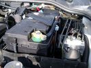
Aux Battery showing ground cable bolt "upside" down 1575 viewsIn order to obtain sufficient height clearance to get the plastic cover back on, I had to install the ground cable to the underside of the battery post connector.
Note the battery vent hose, (approx 5 ft required) is run down into where the windshield washer fluid container is located. There is not much electrical or metal in that area to be corroded by battery gas plus the open end of the vent hose tends to be protected from dirt and stays clean as well.
|
|
288 views
|
|
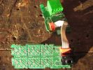
229 views
|
|
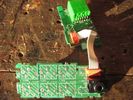
Thread upload11 viewsImage uploaded in thread 17945
|
|
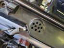
Buzzer located under black plastic cover.12 viewsThe white electrical connector clicks into the buzzer housing that is shown protruding from under the black plastic cover. There is a little tab on the white plastic that has to be squeezed to release the connector. In other words, do not pull on the two conductors.
|
|
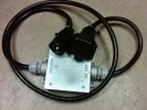
Box Closed with 7 Blade NAS connectors585 viewsBox closed up and ready for use. The box and cable connectors are reasonably weather tight and hence can be submerged for a bit while doing a creek crossing but as with the 3, do not use the creek bed as a parking stall. Similarly, the connector recessed into the bumper will probably remain somewhat dry as long as you keep moving but if you get stopped, well that is another story.
As such, I put a vial of desiccant in the metal box prior to closing it up to reduce corrosion due to moisture build up.
|
|
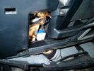
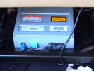
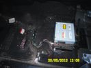
Smooth Talker Amplifier Box mounted below near steering column.179 viewsThe gold look box due to the lighting, (actually black), is the antenna amplifier located near the steering column. It can be put anyway but this seemed an OK location as I ran the antenna connector cable rearward from here to the back corner of the 3 and then up to the underside of the roof glass at the rear. The blue/white thing is the brake light switch that often must be replaced. See the Brake Light Switch file within this Gallery regarding the switch replacement.
|
|

112 views
|
|

343 views
|
|
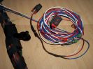
Burnt Bit97 viewsThis bit of wiring going to the connector was so close to bulkhead it got a bit burnt, Its for the clutch switch on a manual used for EPB, It will be replaced connector to pin with the wiring shown.
|
|

D3 A Pillar Connector - C03361 views
|
|
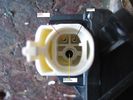
Camera connectors 284 views
|
|
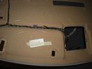
Hidden Mic Connector142 viewsMic connector on upper side of head lining just above & behind sun visor
|
|
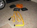
The kit as supplied180 viewsContains carry bag, 2 protector mats, exhaust jack and 7m reinfoced woven hose with bayonet connector to bag (inc non-return valve) and rubber cone for exhaust fitting
|
|
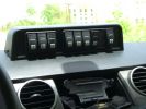
Mud UK switch binnacle453 viewsToo many switches for the roof mounted console, so this binnacle from Mud UK (desigend for the Defender) is an almost perfect match for the leather finished dash in the LR3. Switches, connectors etc bought from them too. From L - R switch functions are:
LH side mounted rack lamps
Driving lamps rack mounted
Spot lamps rack mounted
Bumper mounted driving lamps
RH side mounted rack lamps
Warn winch isolator
Rear mounted rack lamps (reversing)
Telescopic work lamp (fitted behind RH spare wheel)
|
|

heated seats57 views
|
|

power to mats116 views
|
|
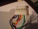
Clock Spring / Rotary Coupler Connector from horn controls209 views
|
|
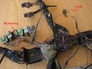
example problems113 viewsInspection showed another Cut Airbag connector, a Missing connector and a few rogue wires at the bottom, the silver one marked Lin, is for the LIN BUS and is supposed to be like that though
|
|
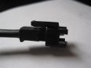
169 views
|
|
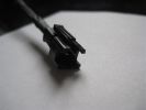
159 views
|
|

Thread upload15 viewsImage uploaded in thread 57865
|
|
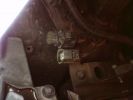
Connector without blanking plug282 views
|
|

Connector for power30 views
|
|

Thread upload15 viewsImage uploaded in thread 108647
|
|

Thread upload10 viewsImage uploaded in thread 124602
|
|

Thread upload20 viewsImage uploaded in thread 122564
|
|

14 views
|
|
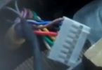
Thread upload20 viewsImage uploaded in new thread
|
|

Thread upload15 viewsImage uploaded in thread 173544
|
|
Thread upload8 viewsImage uploaded in new thread
|
|

Thread upload7 viewsImage uploaded in thread 186178
|
|

Thread upload1 viewsImage uploaded in new thread
|
|

Thread upload1 viewsImage uploaded in new thread
|
|

Thread upload0 viewsImage uploaded in new thread
|
|
Thread upload5 viewsImage uploaded in new thread
|
|

11 views
|
|
Thread upload6 viewsImage uploaded in new thread
|
|

12 views
|
|
Thread upload3 viewsImage uploaded in new thread
|
|

Thread upload1 viewsImage uploaded in thread 120453
|
|
Thread upload23 viewsImage uploaded in thread 143827
|
|

16 views
|
|
Thread upload3 viewsImage uploaded in thread 67721
|
|
Thread upload28 viewsImage uploaded in thread 143827
|
|
Thread upload29 viewsImage uploaded in thread 143827
|
|

Thread upload7 viewsImage uploaded in thread 186178
|
|
Thread upload52 viewsImage uploaded in thread 180400
|
|
Thread upload49 viewsImage uploaded in thread 182595
|
|
Thread upload30 viewsImage uploaded in thread 202058
|
|

Thread upload10 viewsImage uploaded in thread 104513
|
|

D pillar connector34 views
|
|
D pillar connector detail24 views
|
|

Thread upload3 viewsImage uploaded in new thread
|
|
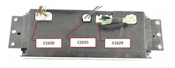
Thread upload3 viewsImage uploaded in new thread
|
|
LHS Headlight Plug Socket24 views
|
|
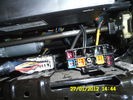
Connector under seat103 views
|
|

Thread upload15 viewsImage uploaded in thread 97249
|
|

Thread upload16 viewsImage uploaded in thread 97249
|
|

Thread upload15 viewsImage uploaded in thread 97249
|
|

Thread upload16 viewsImage uploaded in thread 97249
|
|

Thread upload17 viewsImage uploaded in thread 97249
|
|

Thread upload12 viewsImage uploaded in thread 97249
|
|

Thread upload39 viewsImage uploaded in new thread
|
|

Cooling system hoses - 4.4L petrol V81108 viewsThese are the cooling system hoses on the 4.4L petrol V8. The little odd shaped bleeder hose, (LR006158), shown in the top right hand corner can give problems. There is a plastic tee with a threaded air bleeder outlet located in the middle of the hose. The plastic tee can or will fail due to I guess heat distress.
A BIC pen can serve as a field fix, however for your parts kit, a nominal 3/8" ID hose size brass hose barb inline connector plus a couple of hose clamps is suggested. Better yet is a threaded hose barb brass coupling or a tee and bleeder valve to allow bleeding of the line. Land Rover now makes the plastic bleeder valve that breaks available as a separate part, # LR027661, where 0 is a zero. As such, one can now purchase that part only for addition to your field fix parts kit.
|
|
Rear Seat Warm Connector64 views
|
|
Under seat connectors80 views
|
|

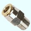
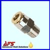
Detroit Fluid DOT air line fittings718 viewsThe picture shows the internal ferrule that is characteristic of the DOT / TUV accepted fittings for highway vehicles. Most often these fittings are metal however the Land Rover John Guest 6mm straight connector is all plastic and has the internal ferrule.
|
|

267 viewsAlign cradle and receiver connectors
|
|
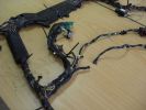
Drivers seat wiring Cut151 viewsSpare connector from my second hand seats shows where wiring to seat gets cut presumably by emergency services.
|
|
Thread upload16 viewsImage uploaded in new thread
|
|
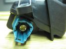
D4 Rear camera connector 142 viewsThis type is used on surround camera system.
|
|
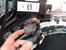
connector for timed climate reciever behind this foam 214 views
|
|
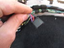
connector for timed climate reciever 186 views
|
|

Thread upload0 viewsImage uploaded in new thread
|
|

Thread upload0 viewsImage uploaded in new thread
|
|

Thread upload0 viewsImage uploaded in new thread
|
|
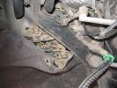
Brake sensor connector ( with 2 red wires connected)302 views
|
|
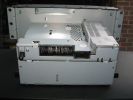
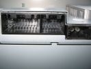
stereo connectors1081 views
|
|
stereo connectors1025 views
|
|
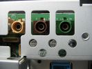
FAKRA-SMB Connectors1054 views
|
|
Thread upload5 viewsImage uploaded in thread 195348
|
|
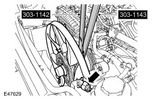
Fan54 views
|
|

Thread upload0 viewsImage uploaded in new thread
|
|
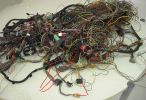
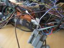
Donar Loom100 viewsThis ball of wires is from a LHD which has been opened and had all audio wires removed, however it is a gold mine for the bits i need. I have pointed out the connectors i know i need for starters near the bottom.
|
|
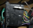
New Speaker Cables.110 viewsThis is the door connector, Main loom to Right, Door side to the left. to the top of the connectors you can see green and Green white wires which are the speaker ones. The door wiring is premium and has two pairs, the main loom was a 1 pair high line, so i am adding the pair you see (one already pinned up) to upgrade the loom to premium.
|
|
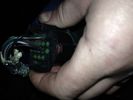
Thread upload33 viewsImage uploaded in thread 102519
|
|
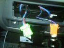
AUX connector253 views
|
|
connectors - back side of the center arm rest122 views
|
|
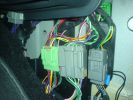
connectors - LHD - passenger footwell159 views
|
|
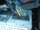
CD 400 back-side connectors145 views
|
|
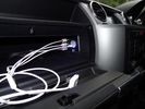
iPod connectors16 viewsAux video and Audio inputs (for nav screen) and usb charge point in upper glovebox
|
|
Used the wire connector that came with the timer - no probs!69 views
|
|
Aux connector in passenger footwell (disconnected)140 views
|
|
RSE Connectors89 views
|
|
DVD Connectors74 views
|
|
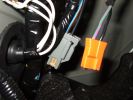
Spare connectors?310 viewsOK - nothing to do with reversing camera - in the wrong gallery :(
In Tow Ball storage side (D4)
|
|
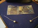
Magnetic connectors105 viewstinned leads
100 grammes+ load bearing by magnets
|
|
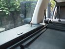
air connector3 viewsposition air connector
|
|

AVIC F500BT-USB129 viewsUSB-Connector in glove box.
|
|

Fitting towbar electrics453 viewsFitting towbar electrics - connectors already in use!!!
|
|
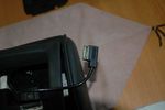
mitsumi screen connector76 views
|
|
alpine connector67 views
|
|
added battery connector for charging direct from vehicle - the solar panel also plugs in here, so can be used for vehicle or trailer charging108 views
|
|

another shot of phone coax connector298 views
|
|
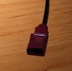
Photo off coax connector on roof top ariel, can you identify it? The name and type is needed.274 views
|
|
DVD Power and Audio Connectors214 views
|
|
DVD Dome Light connector194 views
|
|

View of all 3 DVD connectors202 views
|
|
DVD with Connectors Attached99 views
|
|
88 viewsdvd plug inthe back of the radio
|
|

Fakra SMB Coax Connector Info316 views
|
|

Fan Connector - wires pulled out39 views
|
|
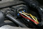
FBH connector on my 3 year old "S"150 viewsNote existing wire on 2nd row, pin 2.
|
|
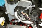
60 viewsfbh connectors - C0925 is comms, C0926 is the power connector.
|
|
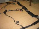
Finished seats area108 viewsThis is a shot of the loom when it was finished from the pass (RHD) door
Both of the seats wiring can be seen, i replaced the conduit on the bottom right and the Yaw rate sensr connector can also be seen in the middle.
|
|
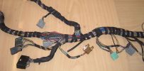
Finished Passenger Kick panel area130 viewsMissing connetor (left most grey) & wiring in, (plastic bracket was broke will use the one in the car) Airbag wires & connector to connector previously cut replaced (on top of grey one to right).
And you can even see the 2 new speaker wires going into the Pass door connector at the very bottom.
|
|
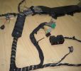
Extra wies at Amp area102 viewsAdditional speaker wires loomed in at Amp connectors can be seen being routed at the top.
|
|

25 views
|
|

90 viewsRed FBH WBUS wire behind fusebox CJB
C2411 C2412
|
|

H9 lamp socket8 viewsWired directly thru HL Connector
|
|

HeadLight Connector Drivers Side (1)65 views
|
|

HeadLight Connector Drivers Side62 views
|
|
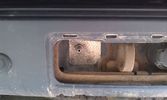
290 views
|
|
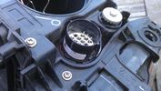
headlamp connector18 views
|
|
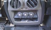
12V outlets for the 2nd row13 viewsI used a part of the old front (which was broke) to cut out a 'mount' for three 12V outlets for the second row.
The outer outlets are switched on whenever the ignition is on as I used the connector that originally was out there.
The middle outlet is connected to the auxiliary battery and is switched on/off through a rocker switch in the central console. (other picture)
This middle one is going to be used for our small fridge that usually resides just there when we're on holiday.
|
|
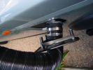
Outside connection to the compressor14 viewsFrom the compressor which is in the booth, the air hose runs to the back of the car.
I was able to install the connector in the space of the second trailer plug (which wasn't installed anyway).
|
|

64 viewsAdded a lead coming from the 12V outlet in the front console. That one is activated only when the ignition is set to I. So that's actually what is referred to as accessories in the manual of the radio. The OEM connector for the head unit did not have any similar lead. The yellow is permanent 12V, the red (on the converting OEM 2 ISO) is the accessories 12V.
|
|
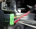
Connector81 viewsOn the back of part YUL501330
|
|

Broken connector unknown 3115 views
|
|

Broken connector unknown 2109 views
|
|
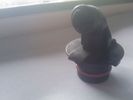
Broken connector unknown 1118 views
|
|
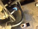
New Connector where worn pipe30 views
|
|
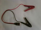
Croc clips58 viewsCrocodile clips with connector without dust/moisture cap.
|
|
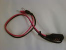
Permanent fixing63 viewsPermanent fixing with eyelet connectors and dust/moisture cap
|
|

2037 viewsEverything pulled to bit\'s in order to get cables in for PC Screen etc.
Note the panel with USB and LAN connectors on, this replaces the LR panel with the ash tray in.
|
|

2271 viewsAll back together again, note the connector panel below the heater controls, it has USB and LAN connections for the Onboard PC
|
|
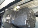
Motor Connectors450 views
|
|

Switch is blue colour thing thru the rectangular opening.3173 viewsThe blue coloured plastic bit thru the rectangular opening is the brake light switch. The fist time, I found it easier remove the switch by dropping the horizontal plastic panel, (two screws), and then slipping my hand in and rotating the switch clockwise 1/4 turn. The second time, I was able to remove the switch thru the rectangular opening and did not need to remove the horizontal lower panel. Obviously, I had to remove the sloping knee pad panel, (note sort of hinged at the bottom so pull back from the top.)
Regardless, do not touch the brake pedal - just let it sit where it wants to. One has to first remove the angled knee pad panel that sits under the steering wheel. It can be pulled from the top corner at the door side. Pulling releases a pair of those U shaped metal clips that LR loves so dearly. You have to pull quite hard. The bottom is held by a couple of plastic fingers in a couple of slots so you pull at the top till the two clips release and then rotate the panel and pull upwards a bit.
To remove the switch, you rotate it clockwise and pull outwards. Rotating the switch clockwise automatically retracts the plunger back into the switch body away from the brake pedal arm.
Similarly when you install the new switch, the required 1/4 turn anti clockwise rotation action releases the plunger so it lays up against the brake pedal arm and at the same time, secures the switch in place.
To remove the electrical wires, the switch will drop below the horizontal pad and hang from the wires so unclipping the electrical connector plug is fairly easy to do.
|
|
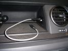
Connectors for Sound out and DC in180 viewsSound out (cable inserted) - connected to Aux connector in passenger footwell.DC in connector is always live
|
|
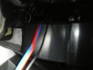
110 viewsview of wires inside dash (from where plug was removed). I ran them through the pre-existing slit in the top of the glove box to wiring loom connector.
|
|

105 viewsextended wire running from glove box to loom connector.
|
|

Fog light & PDC connector17 views
|
|

AV connector for RSE61 viewsdecided to install AV connector in Cubby box between seats (no fridge in my car) so I can store an iPod hidden in there to provide media for Rear Seat Entertainment
|
|

New connector fitted 26 views
|
|

Wiring fault189 viewsThe wire and connector that corrodes causing a fault to the key fob locking
|
|
13 pin connector for 3 cameras47 views
|
|
Connector34 views
|
|
Connector32 views
|
|
Connector36 views
|
|
90 viewspaddle switch connector
|
|

6 viewsFan connector
|
|
n/s/f wheel arch9 viewsthis is where the suspension connectors should be - I think - cannot find them
|
|
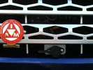
Cabled winch control connector113 viewsAdditional angle bracket made for connector in aluminium attached to red grill. Additional in-line connector between this and the solenoids to allow rad grill to be removed when required.
|
|

Under Drivers Seat - Connector box (being opened)44 views
|
|

Under Drivers Seat - Connector box40 views
|
|

7mm Socket to open connector box22 views
|
|

7mm Socket to open connector box26 views
|
|

Under Drivers Seat - Element connector31 views
|
|
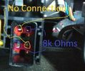
Under Drivers Seat - Element connector - Annotated46 views
|
|
connectors suspension valve133 views
|
|

Seat Electrical connector56 views
|
|

D4 headlight switch connector27 views
|
|

Footwell connector 1 back28 views
|
|

Footwell connector 1 front28 views
|
|

Footwell connector 2 back24 views
|
|

Footwell connector 2 front22 views
|
|

D3 Rear Tailgate switch headliner connector8 viewsThe black connector in the headliner of a D3, showing the brown wire being pushed back and not making contact, and stopping the rear button from working
|
|
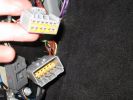
33 viewsConnector in LHS footwell, which connects (amongst other things) to the AUX input on the back of the stereo.
|
|
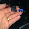
MOST Connector15 viewsThis connector plugs into the back of the Screen (TSD)
|
|
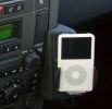
iPod cradle234 viewsThe dealer used the phone fitting and the iPod was installed via cinch connectors. Volume is controlled via the audio, charging function also included.
The sound even with the basic Audio system is terrific!!!
|
|

Part numbers for JAE connectors for the upper hatch switch. 382 viewsThis lists the JAE and Digi-Key part numbers for the electrical connectors for the hatch switch.
I contacted Japan Aviation Electronics and they directed me to Digi-Key in the USA who sell odd lots of the JAE product, odd lots meaning two pins and one connector if that is all you wish.
|
|

JAE connectors for the upper hatch switch and FAKRA connectors for the Sat NAV.539 viewsThis jpg shows some catalog pages listing the MX19 connectors used on the upper hatch switch.
Also shown are the FAKRA connectors that are used on the rear of the Sat NAV.
|
|

Replacement switch from RRS installed on LR3864 viewsThe switch shown is LR part number YUZ500020, the upper rear hatch release switch that is found on the Range Rover Sport.
The switch body is the same switch as on the LR3 except that there is no wiring disconnect on the LR3. Hence when the switch corrodes and requires replacement, the LR solution is to purchase a new handle and license plate light assembly. I instead cut off the old switch and installed a JAE mating connector to the existing wiring and hence just plugged the RRS switch in.
The replacement RRS switch snaps into the same rectangular space in the same manner as the removed LR3 switch, the difference is the JAE male wiring connector.
|
|
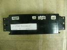
JFC501000V30 viewsCan anyone tell me what each connector is used for?!?
|
|

Thread upload1 viewsImage uploaded in thread 207681
|
|

Thread upload4 viewsImage uploaded in thread 207681
|
|

DISCOVERY 4 - LR4 CONNECTOR QUICK REFERENCE GUIDE59 viewsCONNECTOR QUICK REFERENCE GUIDE
|
|
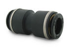
John Guest DOT all plastic fitting717 viewsThis is a picture of the John Guest DOT all plastic union. If you look closely, you can see the DOT imprinted in raised letters on the end of the fitting. This is of a 1/4" connector rather than the 6mm that the 3 requires.
The picture is similar to the air suspension pneumatic fitting union that Land Rover sells as replacement part # STC8580. This is for 6mm OD tubing size. The STC8580 comes with what are called "Collets" at each end that cover up the press to release feature underneath. See the John Guest web site www.johnguest.com under the Pneumatics section and also in Downloads for their catalog for install and remove instructions.
The actual "air brake spec" fitting that Land Rover provides has an interior 4mm OD ferrule that slips inside the 4mm ID of the nominal 6mm tubing. I have not yet been able to obtain the John Guest part number for the LR fitting, only the LR part number. This part number was generated for the RR Classic air systems.
|
|

John Guest (LR part # STC8580) push in straight 6mm tubing to tubing connector730 viewsThis picture is similar to the air suspension pneumatic fitting union that Land Rover sells as replacement part # STC8580. This is a 6mm OD tubing size push in to install straight tubing to tubing fitting. The STC8580 comes with what are called "Collets" at each end that cover up the press to release feature underneath. See the John Guest web site www.johnguest.com under the Pneumatics section and also in Downloads for their catalog for install and remove instructions.
The actual fitting that Land Rover provides has an interior 4mm OD ferrule that slips inside the 4mm ID of the nominal 6mm tubing. Hence the fitting depicted and part number are not actually correct. I have not yet been able to obtain the John Guest part number for the LR fitting.
The fittings that show in this doc are what I call food service fittings rather than transportation or Air Brake fittings. The part LR sells, (STC8580), is the Air Brake type for transportation.
|
|
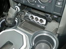
12v/usb connectors166 views
|
|

Connectors51 views
|
|

Auto dimming mirror connector22 views
|
|

LA204-003 - Technical Bulletin - Air Suspension Height Sensor Connector Overlay Harness121 views
|
|

Thread upload13 viewsImage uploaded in thread 156503
|
|

Thread upload11 viewsImage uploaded in thread 156503
|
|
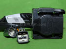
Harness section that runs behind the rear bumper.410 viewsThis is the harness section that clips up inside the rear bumper and includes the circular 7 pin, (6 flat +1 round), NAS socket, and also the 4 pin NAS flat connector.
The two small plug ends connect under the rear left tail light to the harness section that exits from the interior.
The Land Rover part number for the NAS trailer tow kit, (both cables), is YWJ500220.
|
|

Harness that connects inside left rear compartment.445 viewsThis is the harness section that connects behind the left rear interior access panel and exits thru the large grommeted hole to below/behind the left rear tail light.
Note the two rubber grommets on the harness as there is both an interior metal skin and an exterior metal skin behind the left tail light assembly.
The two light grey connectors plug into two existing connectors near the top of the rear left interior access panel. The two darker connectors plug into the second piece of harness.
There is no little separate fuse box either with the NAS spec harness. The fuse box is included with the UK 13 pin dual plug units. If there was a fuse box, it would be on this portion of the harness.
|
|
LR Antenna601 viewsRed connector = GSM
Blue connector = Satellite Radio
|
|
mat plug close103 views
|
|
Connector170 views
|
|

LR Electric Trailer Brake C2590 Female Connector606 viewsThis female connector, C2590, located up above and near the brake pedal is for the Trailer Electric Brake Controller hookup.
The Black wire in the bottom right is pin #3, the ground. The Blue wire to the left is pin #6, the Trailer Brake Controller output going to the rear trailer socket.
The White #4 wire is the 30 amp fusible link, (Link 6E in the engine compartment junction box), for the Brake Controller 12VDC power feed from the battery. Note that this would make a pretty good power source for CB radios and the like if no electric trailer brakes were required.
Pin #5 is a Green wire from the stop lamp switch, (the control input for the Brake Controller).
This plug is standard on all NAS (LR3) vehicles, but unlikely to be found on the D3 spec units.
|
|
Battery Maintainer switch box and connector 721 viewsThe Hammond box contains a DPDT toggle switch with centre off. The Positive and Negative from each battery feeds to the switch. Depending on the setting of the toggle, (full left, full right,or centre off),the respective batteries connect into the pigtail that can stick out thru the grill when one wishes to connect the charger.
This allows one to charge each battery independently via a suitable battery maintainer. I use a CTEK unit that feeds a maximum of 3.3 amps at 14.4 or 14.7 VDC, depending upon setting. The wiring therefore allows for a slow recharge of either of the batteries separately if either one requires such.
|
|
Compressor Electrical Plugs 1406 viewsThis shows the two electrical connectors; the two pronger is the power to the compressor, and the multi-pin connector carries control signals. Also the temporary red plug is where the 6 mm tubing from the centre valve block connects. This line carries both the compressor and exhaust air to and from the springs.
|
|

NAS 7 Blade Round plus NAS 4 Pin Flat Vehicle end Socket527 viewsThis shows the function of each blade when looking into the connector at the vehicle end for the 7 pin NAS plug. The layout is the pin order for most new North American pickup trucks and the LR3/4.
The colour and gauge of the wires feeding into the back of the plug varies even within manufacturer model lines.
Also detailed is the flat 4 pin layout common on smaller trailers not having electric brakes. This includes most U-Haul rental trailers.
|
|

LR3 Brake Wear Sensor Wiring1516 viewsThis 1 page wiring diagram pdf shows that both the front and rear brake pad wear sensors are part of a closed series circuit to ground.
In operation, when all is good, the series circuit is grounded and the amber brake wear warning indicator on the instrument panel is not illuminated.
When the pads on one wheel, either the left front, or right rear, become too worn, the respective sensor is "cut" which results in an open circuit condition. This causes the dash brake wear indicator to illuminate.
The circuit is like the old style Christmas light strings where one burned out bulb caused the whole string to go out.
A quick field fix to get the dash light to extinguish in lieu of replacing the sensor and pads etc is to disconnect the brake pad wear sensor and short across the two open conductors of the vehicle side connector plug. This of course means you now have a normal vehicle, one of the thousands that do not feature brake pad wear information systems.
|
|

Power and Sense connector on door mirror39 views
|
|
![Filename=LR3_Radio_Removal[1].pdf
Filesize=190KB
Dimensions=320x240
Date added=04.Feb 2014 LR3_Radio_Removal[1].pdf](images/thumb_pdf.jpg)
Radio Removal from Radio Stack571 viewsThis shows how to remove the radio from the stack. Basically you remove the H surround first and then at least loosen all the Torx 20 screws left and right sides from the top down starting at the narrow unit that the four way flasher/locking buttons are mounted on.
The units kind of interlock, hence some movement of each is required to remove the radio by itself. I find it best to take out the four way flasher/locking buttons assembly first as that allows access to the fibre optic cable connector into the back of the radio head without too much tugging.
|
|
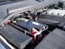
Main starting battery showing 1/2" hole drilled for power cable egress909 viewsView of OEM battery in Left Hand Drive LR3. This is supposed to be a Battery Group BCI 49 or H8 sized battery but in reality is the slightly shorter BCI 94R or H7 battery that fits easier lengthwise, (12 3/8" vs 14").
Note the 10mm hole drilled in plastic of surround to allow for entry of main power cable that runs between batteries. The cable bolts to a spare 6mm threaded hole in the OEM battery cable end; the light gauge wire runs to the front of vehicle to a connector for the CTEK MULTI US 3300 charger. Coloured felts, (red and green), are a material treated to reduce battery post corrosion. The OEM battery ground cable is only about a foot long and runs to an 8mm stud located on the inner fender just to the rear of the fuse case.
|
|

Connector mismatch46 views
|
|

Mirror connectors21 views
|
|

Homelink mirror connector22 views
|
|

314 views
|
|

234 views
|
|
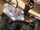
POF connector122 views
|
|
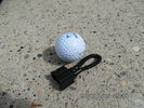
MOST fiber optic loop tool468 viewsThe looping tool in the jpg uses the Land Rover type plastic fiber optic cable with both ends feeding back into a female fiber optic connector that mates with the male fiber optic connectors on the Land Rover system.
The purpose of the loop is to allow one to disconnect MOST connected items such the BlueTooth module or the HK amplifier but allow the MOST system to still transmit signal from the head unit as the circuit would remain closed and hence complete. Of course with the Bluetooth module disconnected, there would be no Bluetooth available, however the radio and NAV would still function.
The looping tool allows one to troubleshoot the system by removing one component at at time from the MOST loop. In other words, what might appear to be a radio problem could be a Bluetooth problem - that sort of thing.
|
|
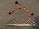
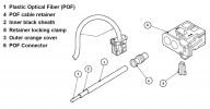
Fibre Optic MOST cable between components.559 viewsThis is a typical section of Plastic Optical Fiber (POF) optic cable with the orange coloured cladding covering the perimeter of the light transparent core. This is used as the MOST (Media Oriented Systems Transport) data transmission medium.
Note that each MOST 1355426 optical connector holds a pair of light conductor cables, one transmitting optical signal in, and the second, optical signal out. When connected to the other cables and devices, the cables form a continuous loop.
The light signal within the cable is red colour as one might expect. One break or disconnect anywhere along the loop shuts down signal transmission to all the connected components.
|
|

Thread upload9 viewsImage uploaded in thread 188234
|
|
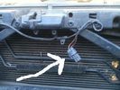
Whats this then?134 views
|
|

How to cable factory BT module (including MOST bus connector)85 viewsInstructions to install Factory BT module in a Disco 3 that has LR aftermarket or no BT module installed
|
|

NAS 7 plus 4 pin LR3 Trailer wiring, battery end. 547 viewsThis is the LR wiring diagram from the engine compartment battery location to the Electric Brake Controller connector, C2590, located under the dash near the brake pedal.
|
|

NAS 7 plus 4 pin LR3 Trailer wiring, trailer end. 498 viewsThis is the LR wiring diagram showing the conductors from the the Trailer Brake Controller connector, C2590, back to the rear combo NAS 7 plus 4 pin sockets.
|
|

25 viewsConnectors for T91-Altox Y Cable
|
|

22 viewsConnectors for T91-Altox Y Cable
|
|

22 viewsConnectors for T91-Altox Y Cable
|
|

20 viewsConnectors for T91-Altox Y Cable
|
|
Thread upload1 viewsImage uploaded in new thread
|
|
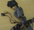
Missing PDC connector114 viewsThe front PDC sensor connector and wiring to the front had been removed.
|
|
Thread upload2 viewsImage uploaded in new thread
|
|

Thread upload13 viewsImage uploaded in thread 122403
|
|
Yaw Rate Sensor102 viewsThe connector for the Yaw Rate sensor was missing and some rogue wires near the Airbag connectors.
|
|
17 views
|
|
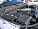
Overview of engine compartment from Main Battery side, (Passenger, LHD), looking across to Aux Battery752 viewsNote labels on main battery cover. The one you cannot read says that an auxiliary battery is installed on the other side. This is to warn service people should they wish to shut off all battery power.
The main starting battery is supposed to be of CaCa separator construction and DIN H8 or BCI Group 49 size. This means Calcium separators Wet Flooded Lead Acid, 13.9" long, 7.5" high and 6.9" wide.
On the Aux battery cover is a label saying to disconnect the blue Anderson single pole connector located under the cover by the brake reservoir. BCI Group 40R battery is small enough that the cover goes back on.
|
|
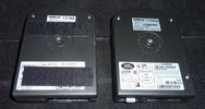
aftermarket and factory BT module55 viewsnotice the additional MOST connector (with white protective cap) for the factory install module
|
|
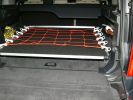
Sliding floor - closed position515 viewsMaterials: 17mm formply, ex 1000mm piano hinge, 2x Haefele 160 kg sliders, timber brackets for the floor to connect the sliders, aluminium angle for leading edge, 50x3mm aluminium flat drilled for the tie-down net connectors, 2x galv iron flat folded to form angle brackets (to secure sliding loadspace to floor), 1 square metre of black carpet to match the back of the seats.
|
|
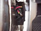
Both connectors wired to aux battery90 views
|
|
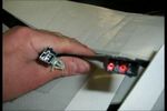
heated seats31 views
|
|
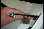
heated mat92 views
|
|

Thread upload24 viewsImage uploaded in new thread
|
|

Thread upload34 viewsImage uploaded in thread 102519
|
|
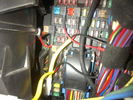
Fuse Panel showing F35P Add A Circuit installed1240 viewsFive amp fuse F35P is located towards the top left in this jpg. The other three Add A Circuit devices are for other items - powering my cell phone base etc.
Note the orientation of the Add A Circuit as this matters. Also one can just see a red tab sticking out from behind the device. The red is the conductor crimp end of a narrow 2.8mm male spade type connector that inserts into one of the "fuse" slots.
|
|
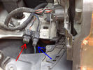
Front PDC Connector106 viewsred pdc
blue lamps
|
|
Thread upload10 viewsImage uploaded in new thread
|
|

Connector from passenger footwell64 views
|
|

Connector at the front of the car120 views
|
|
is this air curtain connector?37 views
|
|
Bl**dy connector on!100 views
|
|
219 viewsThe inner workings of the floor console. You can see the inline fuse holder on the left, which then connects to the chill box connector.
|
|
278 viewsA mess of cables. You can see the HD Radio antenna adapter coming out into the slot for the IHU. You can also see, if you look very closely, the original diversity antenna connector plugged into another adapter to go down to the HD radio unit.
|
|
Back of DVD player as original connectors - unplug middle blue one out put to lcd399 views
|
|
camera installed in towbar cover.362 viewsthere is a plug on the power and video connector so can easily be removed for towing
|
|
Pin swapping86 viewsExample of having routed the wires to their destination connectors to have the pins swapped out.
|
|
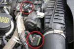
EGR Butterfly Valve Actuator and Air Box Connectors930 viewsRemove the 2 circled plugs.
|
|
Pollution sensor381 views
|
|
Power Connectors70 views
|
|
Radio Noise Suppression Capacitor NNW502820698 viewsThis is the radio noise suppression capacitor, part number LR020488 (previous NNW502820), that is mounted underneath and near the transmission. It is powered by fuse 10 amp F30E in the engine compartment. If F30E blows, (the fuse that also powers the transmission ECU), the problem is probably caused by the failed capacitor, not the ECU. A quick fix is just to disconnect the capacitor and replace the fuse as nothing bad seems to immediately result.
The above radio noise capacitor is not to be confused with LR004160, the ignition noise capacitor which is located under the black plastic engine cover on the right hand side above the air intake towards the rear of the engine.
The ignition capacitor is held on with a single 8mm bolt and a three wire electrical connector. Replacing the ignition capacitor as a routine maintenance prevention action at 100,000 miles, 160,000 km), has merit. It is a do it yourself kind of thing and easier to get at than the radio capacitor underneath.
|
|
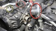
Lifting the EGR Butterfly Housing1018 viewsRemove the bolt circled in yellow. The housing can then be lifted carefully from the front. The \'Y\' shaped duct at the back will swivel at the points circled in red. Be careful of the connector at the back (arrowed) - I snapped the lugs that held it to something back there by pulling the housing up too far!
|
|
ciggy lighter with yellow connector386 views
|
|
pulls out enough to get to connector - i put a rubber mallet in there to keep it open376 views
|
|
Rev Camera Connectors95 views
|
|
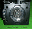
NAS 7 pin + NAS 4 pin Flat Trailer Socket308 viewsThis is the vehicle end of the NAS trailer harness that is located behind the removable plate centered within the rear bumper by the towing loop. Re the four pin flat connector, from the bottom, the exposed bare lower pin is the ground, usually the White wire on a NAS trailer. The next pin up is normally a Brown wire on a trailer and is for the Tail Lights. The third pin, normally a Yellow wire, is the left signal light; the top pin, normally a Green coloured wire, is the right signal light.
Re the round connector, from the notch in the plastic surround, clockwise, the first blade is ignition controlled +12VDC battery power, (only alive when engine running), and on the Land Rover factory harness is an Orange wire; on a NAS trailer, usually Red but perhaps a Black wire.
Next blade clockwise at 3:00 o'clock above, is the Right Turn signal light, a Green wire on the LR harness, and also on a NAS trailer.
At 5:00 o'clock, the next blade is for the Electric Brakes and is Blue on both the LR harness and on a NAS trailer.
The Ground wire is next, White on both the LR harness and on a trailer.
At 9:00 o'clock above, is the Left Turn signal, Yellow on both the LR harness and on a trailer.
The last blade to the left of the line up notch is the Tail Light circuit. On the LR harness, the wire colour is Brown with two White stripes and on a NAS trailer, Brown.
The centre pin is for the Reverse Back Up lights and is Black on the LR harness and often Purple on NAS trailer wiring but can be Black also.
Note that when the socket assembly is installed on the 3, the notch in the plastic surround is on the left - that is rotated 90 degrees anticlockwise to the picture above. In other words, When installed on the 3, the 4 pin flat connector lays horizontal and is located below the round socket.
|
|
Wiring heated seat70 viewsThis picture is taking from behind the driver seat underneath.. the black cable that goes up in the hole is the wiring for the heat elements. There is a connector on the other end, not visible in this pic.
|
|
74 viewsNavi player and connectors
|
|
96 viewsConnectors under my driver seat..
Right connector for Heated seat + airbag ++
Left connector for Seat controll I hink
|
|
72 viewsAnother reading on the heat connector
|
|
64 viewssame connector but too dark (delete)
|
|
73 viewsAnother picture of the same connector
|
|
Heat connector77 viewsThis I found under the Dreaver seat. The connector says Ford Tyco This is for the heat element and the sensor I do beleave
|
|
12v connector50 viewsThis one's for Socket Accessory
|
|
Strain gauge...394 views...I think.
On the left cable - with a latch (?function) and a ribbon connector cable
|
|
Nav_driive and driver seat connectors54 views
|
|
B pilar connector door38 views
|
|
Rear Ac control connector_0133 views
|
|
Connector roof:0235 views
|
|
Rear Ac control connector31 views
|
|
Connector roof:0131 views
|
|
Speaker connector30 viewsThis is the connector used on the bass/midbass speakers
|
|
Speaker connector34 views
|
|
Roof connector41 viewsConnector located left side in the roof of the boot near the D pilar Left hand side
|
|
Roof connector Front42 viewsConnector left hand side in roof
|
|
31 Dash Loom screen conn44 views
|
|
30 dash loom screen41 views
|
|
Screen With Connectors101 views
|
|

Passenger seat connector120 views
|
|
Seat Connector5 views
|
|
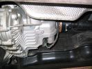
Transfer Box Connector296 views
|
|
84 viewsSunroof drain with connector
|
|
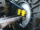
Steering wheel airbag connectors127 views
|
|
31 views
|
|
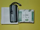
Upper Hatch Release Switch LR Part Number YUZ500020675 viewsThis is the Range Rover Sport switch, Land Rover part number YUZ500020, as it comes out of the box. Note the JAE, (Japanese Aviation Electronics), male wiring connector installed on the end of the power lead.
The rubber cover of the switch is sealed to the plastic body of the switch whereas in the previous switch design, there was no sealing. Also the replaced switch was hard wired into the same harness as the license plate lights - no JAE connector in other words.
|
|

Tailgate Connectors91 viewsDiscobizz's pic
|
|
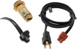
Block Heater and Cord for petrol V8 LR3 North America 120VAC529 viewsThe recommended 120VAC block heater cord is a Temro 3600003. This is a five foot long cord with what is called a Straight connector at the block heater end with holes for two pins; there is also a metal tab located between the two holes serving as the ground conductor. That cord, in addition to having the two pin holes plus ground tab end, is designed for both aluminum and brass heaters as that also matters.
The Land Rover part number for the Block Heater assembly is VUB504640 but is a Temro product not officially marketed by Temro as a Land Rover block heater. The Temro product number is 3100107 which shows as a brass body 30 mm threaded 700 watt 120VAC screw in block heater with a rectangular shaped depression and two pins suitable for the Temro 3600003 cord. Note the word BRASS as it mates with the aluminum OK.
|
|
48 views
|
|

Thread upload3 viewsImage uploaded in thread 187641
|
|
Thread upload0 viewsImage uploaded in thread 188874
|
|

Thread upload13 viewsImage uploaded in thread 154495
|
|

Thread upload13 viewsImage uploaded in thread 154495
|
|

Thread upload9 viewsImage uploaded in thread 154495
|
|
193 views
|
|
183 views
|
|

Thread upload5 viewsImage uploaded in thread 175831
|
|
Thread upload0 viewsImage uploaded in thread 192735
|
|
Voss System 203 connector 6 mm for valve blocks 905 viewsThis is Land Rover part number RQC000030, the Voss fitting for the axle valve blocks. I think it is a Voss System 203 6mm fitting, Voss part number 5 2 03 11 01 00.
The parts bag comes with the white plug inserted in the brass threaded bit with what is called the brass cutting ring placed on the tip of the white plastic plug. The idea is that one screws, (M10 x 1 thread), the brass insert into the appropriate hole with the white plug still in the brass insert. Once the brass is tight, (12 mm wrench), then the white plug is pulled from the assembly leaving the cutting ring down inside and under. One then pushes in the 6 mm tube end about 20 mm or so and the tube slides down thru the brass cutting ring, (2 internal sloped one way cutting ridges). When the tube is in far enough, one pulls upwards a bit and the ring cuts into the plastic such that the tube will not pull out. To remove tube, one unscrews the brass nut and all comes out, sort of like I have shown with the short piece of 6mm tubing. The white plug is a throwaway item upon install of the tubing.
|
|

Voss System 203 Connector cut thru, (similar to in valve block).677 viewsThis is a cut thru of a Voss System 203 connector. The top third of it is similar to the connector that holds the three 6mm plastic tubing lines into each of the front and rear valve blocks.
I say top third, as per the other pictures, the 3 has a Voss assembly that threads into the plastic of the valve block, whereas in the cut thru above, the Voss brass assembly is threading into the brass body of a metric threaded adapter for threading into a standard type metric threaded hole. Note also the two one way sloping ridges of the cutting ring, and the two interal O ring seals that mate with the plastic tubing. There is additionally the small squashed O ring to provide a seal related to the external thread of the Voss cutting ring assembly; (similar to the larger O ring for the brass body external thread).
|
|
26 views
|
|
Thread upload0 viewsImage uploaded in thread 167688
|
|
Thread upload13 viewsImage uploaded in thread 190668
|
|
Thread upload11 viewsImage uploaded in thread 207493
|
|
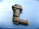
Headlight washer pipe connector60 views
|
|

Thread upload3 viewsImage uploaded in thread 195348
|
|
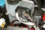
Thread upload1 viewsImage uploaded in thread 195217
|
|
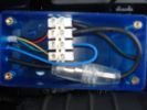
119 viewsConnector block, fuse etc all fits inside. Drilled the holes myself. Should really of used red wire for the +tive, but didnt have any.
|
|

New Wiring Overlaid98 viewsSport loom gives me length info to position replacement connector and its wiring in. Her you can see the new wires lying over the top of the cut of ones.
|
|

Electrical Connector Sleeve Replacement ZF 6HP26972 viewsThis 3 page pdf with pictures shows how to replace the sleeve that holds the multipin electrical connector that passes thru the transmission body to the Mechatronic unit.
The install of the sleeve is more difficult than the removal in that one must not rotate the sleeve as damage to the internal pins can result. The pan must be first removed to both remove and install the sleeve.
|
|

Mechatronic Sleeve Removal and Install Instructions1057 viewsThis 3 page pdf with pictures shows how to remove and install the Mechatronic sleeve that tends to leak tranny oil after about ten years. Even if not leaking, replacement when doing a pan/filter change at the ten year mark is suggested.
Note the 3mm or less requirement when sleeve installation is completed; also that rotation of the sleeve during the install procedure can do damage to some internal pins - hence do not rotate the sleeve when trying to insert it or in getting it to lock in place - not so easy it seems.
|
|
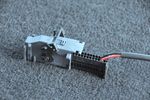
Power connector30 views
|
|
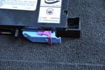
Alternative connector31 views
|
|
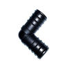
20mm Barbed Connector 90 deg22 views
|
|
|
|
|
|