| Search results - "Central" |

5 viewselaborazione scarichi aspirazione rifacimento frizione più robusta distribuzione egr killer centralina remapping
|
|
USB NEL CASSETTO CENTRALE83 views
|
|
Thread upload1 viewsImage uploaded in new thread
|
|

Central Door Locking Operation Description1458 viewsThis 17 page pdf explains how the door locks are supposed to operate. Note that on page 9/17, the explanation of the operation of the hood ajar switch is wrong. It operates similar to the door and tailgate ajar switches; that is when a "door" is closed, the switch is closed to maintain a ground back to the CJB. Opening the hood, door, or tailgate removes the ground breaking the circuit and hence allows for an alarm condition.
|
|
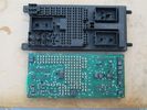
central junction box, without fuses.204 viewsthe print circuit board is easily dropped, after you pull out all the fuses.
|
|
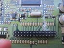
Central Junction Box - Broken! 186 viewsfound 2 resistors badly desoldered and a big scratch.
|
|
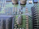
central junction box - resistors badly pulled 181 viewscentral junction box - two resistors pulled, PCB scratched
|
|
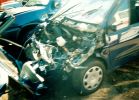
Not much left of bonnet!281 viewsCrash in a Renault Scenic
Head on colition with a Nissan Terrano he lost control came over the central reservation & ended coming at us sideways!
We hit him in the back wheel arch & spun him around so he then hit my drivers side, I walked away having a air bag wife had broken solder coursed by the seat belt, but it did save her life!
Our car was trashed but it did its gob (was only 2 weeks old!) the bonnet tacking lots of energy out of the collision & the inertia staying relatively in tacked.
|
|
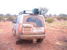
Rained for 14hrs across central Oz120 views
|
|
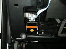
Height controller by marcap59975 viewsCentral unit beta test
|
|
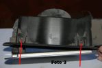
Foto 3 - Rimozione portello143 viewsInserire un tondino metallico di 2mm di diametro per abbassare le mollette che bloccano la struttura del portello.
Bisogna anche rimuovere il dispositivo della chiusura centralizzata indicata dalla freccia grigia della foto 4 premendo le 4 linguette con due pinze.
Ogni lavoro � fatto a rischio e pericolo di chi lo fa, non mi assumo alcuna responsabilit� per eventuali danni causati a persone o cose.
|
|
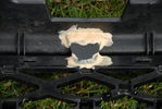
Central bridging piece joining D3 + RRS together.179 views
|
|

75 views
|
|
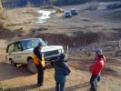
View of the Quarry\'s Central Area113 views
|
|
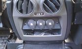
12V outlets for the 2nd row13 viewsI used a part of the old front (which was broke) to cut out a 'mount' for three 12V outlets for the second row.
The outer outlets are switched on whenever the ignition is on as I used the connector that originally was out there.
The middle outlet is connected to the auxiliary battery and is switched on/off through a rocker switch in the central console. (other picture)
This middle one is going to be used for our small fridge that usually resides just there when we're on holiday.
|
|

An extra 12V outlet16 viewsOn the passenger side, I added a 12V outlet which is fed through the fuse box in the rear and adds as such an outlet for whatever charger we don't want to have lingering around around the central console.
The USB charging outlets are visible as well :)
|
|
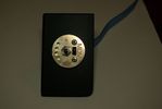
Controller centralina ANITAS D321 views
|
|
Controller centralina ANITAS D3 bis22 views
|
|

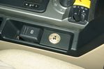
Switch centralina sospensioni 136 viewsImmagine del posizionamento occultato dello switch della centralina sospensioni
|
|

Switch centralina sospensioni36 viewsImmagine dell'installazione dello switch della centralina sospensioni
|
|

15 viewsilluminazione zona anteriore con alogena di serie centrale
|
|

15 viewsilluminazione anteriore con solo led centrale
|
|
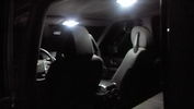
19 viewsilluminazione solo con led centrali
|
|
CALENDAR 2011246 views
|
|
58 views
|
|

Key in Ignition Electrical Wiring Diagram1051 viewsThis shows the key in ignition wiring, (LGW, 1.5D), running from the key lock cylinder to the Central Junction Box, (CJB), thru 5 amp fuse F40P, located in the fuse box behind the lower glove box door.
You can remove the 5 amp fuse and the good news is that the ignition chime will not sound any longer; the bad news is that a bunch of other circuits that rely on knowing if the key is in or out no longer work.
Also note the Transponder Coil D219 reference.
|
|

Central Aust July 2009116 viewsKallamernia Station, Near Lake Eyre, in the Simpsom.Lake Kallamerna in the distance.
|
|
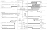
Power Window Circuit centered on Central Junction Box (behind glove box fuse panel)733 viewsRelay 143, the power window relay, and most other relays and FET's as well are built into the back of the passenger side behind the lower glove box fuse panel.
As such, the relays etc are not removable, jump-able, or serviceable.
|
|
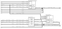
Power Window Circuit Sheet 2 Central Junction Box to Passenger Front Switch365 views
|
|

Power Window Circuit Sheet 3 Central Junction Box to Rear Switches391 views
|
|
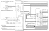
Power Window Circuit Sheet 1 from Battery to Central Junction Box (fuse box behind glove box)352 views
|
|

Stop Light Lamp Circuit pdf2491 viewsThis pdf shows the brake light circuit for the NAS LR3.
Note that power for the brake light bulbs can come either thru the brake light switch power feed /contacts plus also from the Hill Decent Control, (HDC), system relay located within the Central Junction Box, (CJB) - yes two separate sources of power for the brake light bulbs. This would tend to explain how a brake light circuit concern shows up as a hill decent fault message; also why lesser vehicles without hill decent braking mechanisms, (HDC), never display this sort problem when a brake light bulb or switch acts up. You never have a problem related to a system that does not exist.
Additional evidence of the relationship of the HDC and the tail light circuit is demonstrated by when the HDC actually acts to slow the 3 down, the brake lights automatically illuminate even if the slowing action was merely retarding the engine speed or shifting to a lower gear, (in other words, no foot on the brake pedal).
There is also a tie in to the Cruise Control and hence a failing brake light switch can affect cruise operation or just create false Cruise Control messages. To further complicate the issue, while there are no messages generated, operation of the radiator electro viscous fan can also be negatively affected by the fouled set of secondary contacts within the brake light switch. This is all because the NC contacts within the brake switch send misleading messages to the ECU.
While the ground wire design is similar to other vehicles, note the grounds for the brake light filament and the reverse light filament are common on each side. That means that if one has a non functioning brake light on one side, the reverse light may not also work or that some problem with the reverse lights could back feed into the brake lights. This situation while unusual, can result when grounds are corroded probably due to swimming in rivers and creeks or just routine driving in a marine environment.
|
|
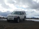
Calendar 2010257 viewsAugust in New Zealand. Driving up to the Tukino ski field. Mount Ruapehu, central North Island.
|
|
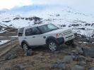
Calendar 2010268 viewsAugust in New Zealand. Driving up to the Tukino ski field. Mount Ruapehu, central North Island
|
|
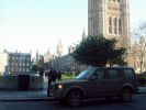
Outside Houses of Parliament208 viewsIt felt like my car had a big neon sign on it today driving in to Central London!!!!
|
|
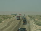
D3\'s leaving shit-central heading towards Molares93 views
|
|

The Rock195 viewsUluru - Central Australia
|
|
|
|
|
|
|