| Search results - "Box" |
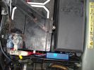
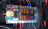
138 viewsThe weatherproof junction box fits neatly down the front of the battery, all contained inside the battery box.
|
|

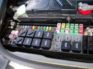
find relay 7 in engine compartment fuse / relay box 802 views
|
|
Bobbycrispbox195 views
|
|

Bobby checking the terrain216 views
|
|
Fallen tree200 views
|
|
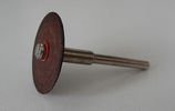
Disco abrasivo - Abrasive disc20 viewsDeclino ogni responsabilità per i danni che eventualmente farete direttamente o indirettamente seguendo questi consigli.
Per aprire la chiave ho usato un disco abrasivo da modellismo montato su un minitrapano. Deve giare velocemente.
Decline all responsibility for any damage that may directly or indirectly do by following these tips.
To open the key I used an abrasive disc mounted on a mini-drill. It must turn quickly.
|
|
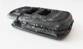
Tagliare lungo il perimetro della chiave - Cut along the key perimeter16 viewsI gusci sono saldati ad ultrasuoni. Con il disco tagliare lungo il perimetro della chiave in corrispondenza della giunta: lo spessore è di circa mm.3. Io non sono andato fino in fondo per evitare di danneggiare qualcosa, una volta inciso il solco per mm.2,7 ho fatto leva col cacciavite e ho strappato il materiale restante.
The body is ultrasonically welded. With the disc cut along the perimeter of the key in correspondence of the joint: the thickness is approximately 3mm. I have not gone all the way down
|
|

Tagliare per eliminare parte del coperchio - Cut to remove part of the cover14 viewsE' meglio prima levare il circuito stampato e poi la lama della chiave, per evitare di danneggiarlo. Tagliare sopra il tasto superiore per rimuovere solo la parte con i tasti.
Is better to remove the printed board first then the key, to prevent damage. Cut over the top button to remove only the part with the buttons.
|
|

Estrarre il circuito stampato con la batteria - Exctact the printed board with the battery18 viewsRimossa la parte superiore del contenitore, estrarre il circuito stampato sollevandolo leggermente dalla parte della batteria.
Removed the top of the box, pull out the printed circuit board slightly lifting from the battery side.
|
|

sky boxes12 views
|
|

Chiave aperta12 viewsUna volta estratto il circuito stampato, facendo leva col cacciavite sulla parte rimasta attaccata ho prelevato la lama della chiave da inserire nel box nuovo.
Once you remove the printed circuit board, leveraging with the screwdriver on the part remained attached, I picked up the blade of the key to be inserted in the new box.
|
|
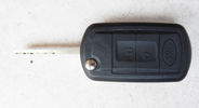
Chiave finita - Finished key17 viewsHo iserito il tutto nel nel nuovo contenitore pagato €4,00, ho incollato con la colla cianoacrilica, ne basta poca, e questo è il risultato.
I put all in the new container paid € 4.00, I glued with super glue, it only takes a little, and this is the result.
|
|

Opened box123 views
|
|
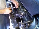
Putting all the bits back in52 viewsNotice the rope (Kevlar) coming out of the actuator box on the right side.
|
|
they broke my box106 views
|
|
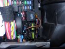
Permanent 12V supply271 viewsPhoto taken of TFC\'s D3 showing where you can take a permanent +12V supply, from the main fuse board behind the glove box.
|
|
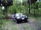
D3 in the Mary River Flood plains50 viewsFamily was down South with the In-laws, so I went for a drive on Boxing Day - which is the monsoon time, or \'The Wet\'. Was doing a test run with the off-raod trailer in preparation for the trip I was planning to the Kimberley six months later. Couldn\'t quite make it out of the creek, so a self-recovery was in order. Good thing it all worked, as I didn\'t see another car in over four hours. They were too smart to drive down the track I was on!
|
|

oil seems to be coming from grommet on auto-box88 views
|
|

Oil leak on autobox/engine95 views
|
|
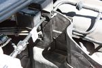
110 viewsBolts through the plastic box. These function as studs for the traxide brain to be mounted to.
|
|
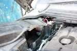
120 viewsModified aux battery box cover with shape of battery to battery cable. I also removed the tab which was fouling my traxide brain mounting bolts.
|
|
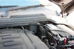
110 viewsBattery to battery cable in main battery box
|
|

97 viewsOut at the C pillar. From here wires were threaded through the rear seatbelt anchor point into the commercial box, which is the hub of all the wiring and CarPC installation
|
|
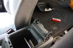
77 viewsRemoved cubby box lid
|
|
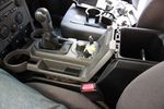
90 viewsLifted floor console upper panel to enable cubby box removal
|
|
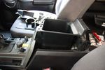
71 viewsCubby box coming out
|
|
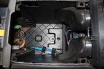
76 viewsInside the cubby box
|
|
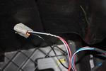
109 viewsThis is the plug for the accessory socket at the rear of the cubby box. On commercial D3 such as this one, there is no accessory socket so this plug is unused. I tapped into the 12V wire as an ignition feed. This will feed a relay coil which opens up power from the aux battery. Like this I can still retro fit and make use of the accessory socket later on.
|
|
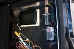
97 viewsDeciding on a layout for the electrical stuff. Bottom right of pic is a fusebox which will take the input power from the traxide kit, then relay box and 12V regulator, ignition busbar and homemade regulated 12V busbar. Big black box is the CarPC
|
|

68 viewsJungle of wires coming out of the cubby box
|
|
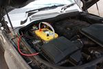
124 viewsOptima Yellow Top in battery box. This is the version with side terminals so there will be some modifications to be done to fit
|
|

79 viewsExtra USB sockets mounted to front of commercial box, just behind cubby box
|
|

2011 passenger fuse box layout50 views
|
|
![Filename=2012-03-22_16_33_53[1].jpg
Filesize=329KB
Dimensions=1706x1280
Date added=23.Mar 2012 2012-03-22_16_33_53[1].jpg](albums/userpics/20728/thumb_2012-03-22_16_33_53%5B1%5D.jpg)
Bashed Box29 views
|
|
whas31 views this box?
|
|

Transfer box drain/fill26 views
|
|

Thread upload1 viewsImage uploaded in thread 187474
|
|

Thread upload2 viewsImage uploaded in thread 187474
|
|

Thread upload0 viewsImage uploaded in thread 187474
|
|
Toolbox2 views
|
|
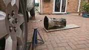
Thread upload2 viewsImage uploaded in thread 201091
|
|

Thread upload1 viewsImage uploaded in thread 201091
|
|
Thread upload2 viewsImage uploaded in thread 201091
|
|
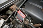
TT Box Location146 viewsSmall TT box, easy to fit on spare battery compartment
|
|
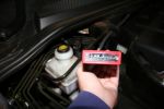
TT Box Jumpers134 viewsEasy to remove cover and setting the jumpers to either higher or lower settings
|
|
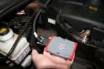
TT Box Size125 viewsSize of the new TT box shown in my hand
|
|
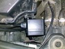
Possible Location for wireless remote box situated to the front of the airfilter housing112 views
|
|

308-Four-Wheel-Drive-Systems-TransferBox60 views
|
|

Commercial box opened74 views
|
|

Commercial box removed68 views
|
|

Alternator and Regulator Wiring Diagrams, TDV6 and petrol V8 and V61989 viewsThis is a three page pdf that shows the alternator and regulator wiring for the petrol V6, petrol V8 and TDV6. The pdf can be either printed or by right clicking on the displayed pdf, rotated as required for viewing.
Of interest is that the regulator gets its instructions primarily from the Engine Control Module (ECM) and only secondarily from the vehicles electrical buss. The conductor from the battery thru the 5 amp fuse F20E is to provide initial power to excite the alternator at startup and then secondarily, to instruct it if the PWM signals were not available. Primary instructions to and from the ECM are thru the two other conductors via a digital like Pulse Width Modulated (PWM) signal.
If F20E, the 5 amp engine compartment fuse box fuse is blown, the red alternator light on the dash will be illuminated. This means that the alternator could be OK, but if the F20E fuse is blown, no electricity will be generated. Hence check the F20E fuse if you get a red ALT light or some indication of the alternator not working.
Regarding operation of the red ALT light on the dash, it is not the regulator within the alternator that tells the red light to illuminate, or not, but instead the ECM. This is the reason the red light does not function in the same manner as with older vehicles. With the 3, sometimes you have illumination and sometimes not depending upon what the ECM is thinking. What this means is that you can have an alternator that is failing but the red light does not illuminate as the ECM is compensating for reduced alternator output - maybe by draining the battery and or cutting back on vehicle electrical loads such as shutting off or cycling the radio amplifier or heated seats.
|
|

Gearbox Protection624 views
|
|

501-12-cool-box install instructions / german language66 viewsCool Box Discovery 4 installation instructions - german version
|
|

6 Way Fuse Box9 views
|
|
Thread upload1 viewsImage uploaded in thread 156005
|
|

Sideview of gearbox plate623 views
|
|

C2243R80 viewsDescription: Main harness to engine compartment harness Location: Behind passenger compartment fusebox
|
|
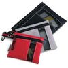
Husky Organizer Bags123 viewsUse these or something similar if you own a refrigerator cubby box and want to use it for storage and occasional fridge. They go for under $7.00 at Home Depot.
|
|
they broke my box103 views
|
|
a-20200928_Vigor166_Box13 views
|
|
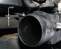
Airbox Bracket Bent causing Leak81 views
|
|
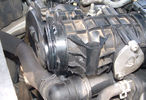
Airbox to EGR Butterfly Valve Housing Leak96 views
|
|
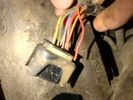
Broken wire Transfer box actuator motor harness 2 - temp sensor wire25 viewsBroken wire Transfer box actuator motor harness 2 - temp sensor wire
|
|
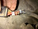
Repaired Transfer box actuator motor harness 2 - temp sensor wire24 viewsRepaired Transfer box actuator motor harness 2 - temp sensor wire
|
|
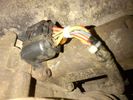
Repaired Transfer box actuator motor harness 3 - temp sensor wire26 viewsRepaired Transfer box actuator motor harness 3 - temp sensor wire
|
|

Add A Circuit Littelfuse Data sheet2278 viewsThe switch connects to what Littelfuse brand calls an Add-A-Circuit model FMH200BP which is an adapter that plugs in place of a Mini fuse and then has space for two Mini fuses, (original and a second one). In this install, only the original 5 amp fuse was used - adapter was so as to route power from fuse box thru fuse, then rocker switch, and then back to fuse box.
Before you install the Add A Circuit for this application, take an ohm meter and trace out the circuit path of the four slots that fuses could insert into. The path is more complicated than one might first think. As such, the orientation of the fuse holder in the socket matters for this application - that is for a circuit diverter, rather than accessory adder.
|
|
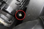
Air Box Lower Securing Bolt1072 viewsThis bolt must be undone in order to remove the air box. It is long and tricky to get out and could be dropped easily.
|
|
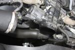
Air Box Removed1058 viewsView showing air box removed from front of EGR butterfly valve housing
|
|

Thread upload7 viewsImage uploaded in new thread
|
|
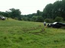
AndrewS winching BobbyCrispBox\'s motor out of the bog82 views
|
|
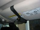
Cam mounted on sun-visor242 viewsI usually place something in between the sun-visor and the roof lining to give the cam a better angle. At Boughrood it was a roll of PVC tape. For Boughrood I also placed a small cardboard box between the cam and the sun-visor to bring the cam away from the dirty section of windscreen.
|
|
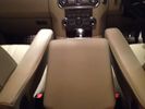
My12 Armrests25 viewsMY12 Armrests (6 speed gearbox model)
|
|
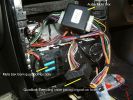
154 viewsInstall Hands free HCB-700 in A class
|
|

Auto Gearbox Drain and Refill145 views
|
|

Thread upload9 viewsImage uploaded in new thread
|
|
Thread upload19 viewsImage uploaded in new thread
|
|

Thread upload6 viewsImage uploaded in new thread
|
|

D4 Auxilliary or Second Battery installed in Aux Battery Box216 views
|
|
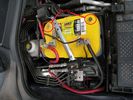
D4 Auxilliary or Second Battery installed in Aux Battery Box, Vents Circled191 views
|
|
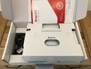
b-20200928_Vigor166_Box_Contents16 views
|
|

TransK9?b1042 views
|
|
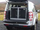
B12 TransK9 Dog Transit Box for Discovery 53 views
|
|
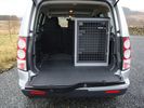
B24 TransK9 Dog Transit Box for Discovery 471 viewsThis box is designed specifically for the Discovery so that the 6th seat can also be used.
|
|

Thread upload12 viewsImage uploaded in thread 53236
|
|

20 viewsTransK9/B24 with fully grown Boxer
|
|

13 viewsTransK9/B24 with Boxer
|
|
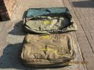
Canvas box bags127 viewsThe wolf pack type bags we get for 2x and 3x boxes.
|
|
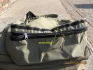
Canvas box bags120 viewsThe fold over lip to cover the zip with welcro.
|
|
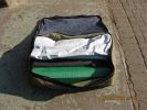
Canvas box bags126 views
|
|
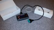
BAS BOX14 views
|
|

Thread upload19 viewsImage uploaded in thread 126959
|
|
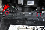
Fuse box earth17 views
|
|
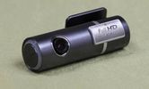
hids4u blackvue hd unit black box153 views
|
|

8 views
|
|
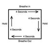
Thread upload20 viewsImage uploaded in thread 187103
|
|
47 views
|
|
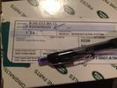
Aux Input Panel Box59 viewsCorrect Part Number
|
|

38 views
|
|

Thread upload15 viewsImage uploaded in new thread
|
|
Thread upload14 viewsImage uploaded in thread 173460
|
|

Thread upload1 viewsImage uploaded in new thread
|
|
8 views
|
|
o/s/f16 views
|
|
o/s16 views
|
|
n/s/f15 views
|
|
inside16 views
|
|
75k16 views
|
|
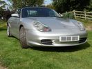
front18 views
|
|
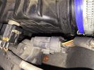
6 views
|
|

88 views
|
|

85 views
|
|
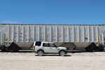
Thread upload4 viewsImage uploaded in thread 157613
|
|

Thread upload11 viewsImage uploaded in thread 148973
|
|
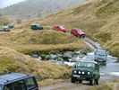
Another Highland 4WD Club Run. Boxing Day 2005, south of Inverness. We're in the second green 90.78 views
|
|

Thread upload4 viewsImage uploaded in new thread
|
|
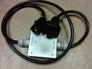
Box Closed with 7 Blade NAS connectors586 viewsBox closed up and ready for use. The box and cable connectors are reasonably weather tight and hence can be submerged for a bit while doing a creek crossing but as with the 3, do not use the creek bed as a parking stall. Similarly, the connector recessed into the bumper will probably remain somewhat dry as long as you keep moving but if you get stopped, well that is another story.
As such, I put a vial of desiccant in the metal box prior to closing it up to reduce corrosion due to moisture build up.
|
|
Thread upload0 viewsImage uploaded in thread 177818
|
|

Thread upload14 viewsImage uploaded in new thread
|
|
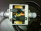
Box open showing Hella Relays and Putco Load Resistors749 viewsInterior of the box - note the two gold coloured 6 ohm 50 watt load resistors are a bit distant from the other items so as to provide some separation for dissipation of the heat generated.
Rather than a moulded plastic weather resistant box which I would have preferred, I used a bulky and much heavier metal weather tight style electrical box so the metal can act as a heat sink.
|
|

Thread upload2 viewsImage uploaded in new thread
|
|
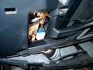
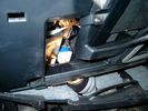
Brake Switch Visible thru Opening4973 viewsThe blue and white bit is the switch; the sort of gold appearing box,(it is really black), you will not see in your 3 as it is a Smooth Talker brand amplifier for my Blackberry phone antenna. This install is detailed in the SmoothTalker phone antenna section of my gallery.
One way to remove and install the switch is to lower the "horizontal" panel above the brake pedal as shown where the flashlight head is located. To actually remove the switch, you slide your hand thru the gap and rotate the switch clockwise 1/4 turn while watching thru the rectangular opening. Installation of the new switch is the reverse of above - 1/4 turn counterclockwise.
Before you remove the switch, note its orientation - horizontal with electrical wires to the left. That is the way it should look after replacement as well.
The second time I replaced the switch, I did it all thru the rectangular opening and did not remove the horizontal panel - that is experience helping out.
The knee kick you have to remove regardless. It is sort of hinged at the bottom so you just pull at the top and sort of rotate the knee panel and then pull upwards for two plastic "fingers" to clear the slots they reside in.
|
|
Smooth Talker Amplifier Box mounted below near steering column.179 viewsThe gold look box due to the lighting, (actually black), is the antenna amplifier located near the steering column. It can be put anyway but this seemed an OK location as I ran the antenna connector cable rearward from here to the back corner of the 3 and then up to the underside of the roof glass at the rear. The blue/white thing is the brake light switch that often must be replaced. See the Brake Light Switch file within this Gallery regarding the switch replacement.
|
|
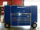
KING OF TOOL BOXES108 views
|
|
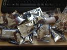
LEDs16 viewsBig box of LEDs from HIDS4U
|
|
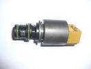
Thread upload15 viewsImage uploaded in thread 55986
|
|

monitor above chubby box - fold away behind the box85 views
|
|
Thread upload3 viewsImage uploaded in new thread
|
|
Thread upload3 viewsImage uploaded in new thread
|
|

Thread upload2 viewsImage uploaded in new thread
|
|

Thread upload1 viewsImage uploaded in new thread
|
|
Thread upload2 viewsImage uploaded in new thread
|
|
Thread upload1 viewsImage uploaded in new thread
|
|
Thread upload0 viewsImage uploaded in new thread
|
|
Thread upload1 viewsImage uploaded in new thread
|
|
Thread upload0 viewsImage uploaded in new thread
|
|
Thread upload2 viewsImage uploaded in new thread
|
|

Thread upload1 viewsImage uploaded in new thread
|
|
Thread upload4 viewsImage uploaded in new thread
|
|
Thread upload0 viewsImage uploaded in new thread
|
|
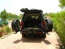
Rear end open330 viewsEccentric latch clamps for wheel carriers are very strong. No rattles on graded roads. Canvas seat covers from \'Escape\' in SA on rear jump seats can be seen, and Front Runner Wolfpack storage boxes - great for toolkit, winch and recovery straps etc.
|
|
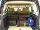
Load space368 viewsShows the SA Front Runner Wolfpack stacking plastic storage boxes that I keep laod straps etc in and the 2nd is tool kit, spare belts, jerry can funnel and tools, plus airline and tyre inflator/deflaotr for ARB on-board compressor, HD jump leads. ARB Winch pack (Orange)with strops, snatch blocks, shackles, gloves, and 2 ARB recovery dampers. Really great 4x4 1st Aid kit from Outdoors warehouse in SA. LRs own loadspace guard - not the best design if you want to store a long load. Mods to be carried out!
|
|
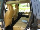
Escape seat covers rear254 viewsJust shwing the good fit of these canvas seat covers made in South Africa. The whole set for a 7 seat HSE £542 with air freight as unaccompanied baggage (inside 5 Front Runner Wolf pack boxes) costing and additional £150 - still a bargain out here!
|
|
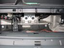
Top glove box removed 296 views
|
|
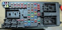
202 viewsfuse plane (this is what you see behind the glovebox)
|
|
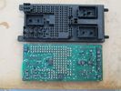
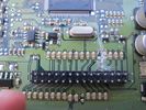
central junction box, without fuses.204 viewsthe print circuit board is easily dropped, after you pull out all the fuses.
|
|
Central Junction Box - Broken! 186 viewsfound 2 resistors badly desoldered and a big scratch.
|
|
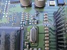
central junction box - resistors badly pulled 181 viewscentral junction box - two resistors pulled, PCB scratched
|
|
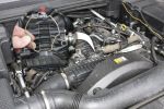
Remove Clip951 viewsRemoving the air box/EGR butterfly housing securing clip
|
|
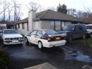
Toy box opened for cleaning468 viewsWork this out! 3x4x4, 1x4x2, 1x2x1, 1x2x0. (Hint: There is a motorbike hiding behind the BMW). SWMBOs car is off to visit the out-laws so I got to wash my toys.
|
|
110 viewsTFC compressor in auxillary battery box
|
|

Control Box61 views
|
|

Cool Box Removal110 views
|
|

21 views
|
|
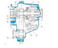
59 views
|
|

18 views
|
|

42 views
|
|

23 views
|
|

Thread upload6 viewsImage uploaded in new thread
|
|
39 views
|
|
Thread upload4 viewsImage uploaded in new thread
|
|
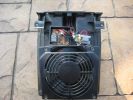
cool box120 views
|
|
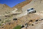
453 viewsMore photos coming soon. 7000 km with NO problem. Only took a 6th spare wheel, a tool box, air compressor, window shades. What a great Disco !
PS: note that my disco has manualy inflatable air sping in addition of the standar terrain response.
|
|

238 views
|
|
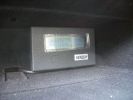
Genesis digital battery system - monitor in top glovebox323 views
|
|

Thread upload4 viewsImage uploaded in new thread
|
|

161 views
|
|
8 views
|
|
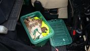
Thread upload6 viewsImage uploaded in thread 142003
|
|

8 views
|
|

Thread upload11 viewsImage uploaded in thread 142003
|
|

6 speed oil mannol AG556 views
|
|
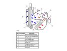
Thread upload24 viewsImage uploaded in thread 152525
|
|

D4 Cooler cubby box116 views
|
|

D4 Auto Gearbox Oil Cooler 77 views
|
|
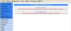
Blackbox-Soloutions Faultmate MSV2 Discovery 4 fuel burning heater test options.154 views
|
|
Big Box31 views
|
|
Thread upload1 viewsImage uploaded in thread 193544
|
|
Thread upload3 viewsImage uploaded in thread 200510
|
|

Thread upload4 viewsImage uploaded in thread 200510
|
|

Thread upload2 viewsImage uploaded in thread 200510
|
|

Thread upload1 viewsImage uploaded in thread 200510
|
|

Thread upload2 viewsImage uploaded in thread 200510
|
|

5 views
|
|

D4 lights in box23 views
|
|
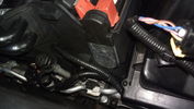
Cable routed from secondary battery box to front grille113 views
|
|
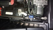
Fuse mounted in secondary battery box111 views
|
|
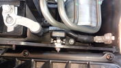
Fuse mounted in secondary battery box95 views
|
|
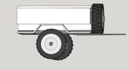
Thread upload10 viewsImage uploaded in thread 126243
|
|
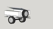
Thread upload12 viewsImage uploaded in thread 126243
|
|
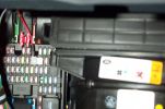
Tapa-circuit388 viewsTapa-circuit fitted to fuse box behind glove box. Red cable to top is the fused output cable leading to the PDA charger
|
|
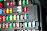
Tapa-Circuit Fuse Tap411 viewsTapa-circuit fuse tap fitted in existing fuseway provides extra fuseway which I have used to hard wire my Tomtom Sat Nav PDA. The fused output feeds into a female socket (Cigar lighter sized) into which the tomtom power adaptor is plugged. All hidden away behind the glove box.
|
|
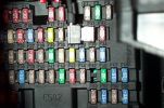
Tapa-circuit Fuse Tap435 viewsTapa-circuit fuse tap fitted in existing fuseway provides extra fuseway which I have used to hard wire my Tomtom Sat Nav PDA. The fused output feeds into a female socket (Cigar lighter sized) into which the tomtom power adaptor is plugged. All hidden away behind the glove box.
|
|
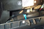
Hard wired tomtom497 viewsThe fused output from a tapa-circuit feeds into a female socket (Cigar lighter sized) into which the tomtom power adaptor is plugged. All hidden away behind the glove box.
|
|

69 views
|
|
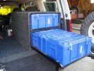
Drawer box321 viewsHome made drawer setup, 4 x amo boxes.
|
|
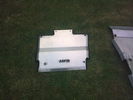
103 viewsASFIR gearbox guard
|
|

Main secondary gear repair bush491 viewsPDF file of engineering drawing of bush turned up to repair the main secondary gear in the EPB gearbox.
Old gear has to be drilled out accurately to the external diameter of the bushing shaft.
|
|
Thread upload15 viewsImage uploaded in thread 139047
|
|

Thread upload2 viewsImage uploaded in thread 198243
|
|

Thread upload1 viewsImage uploaded in thread 198243
|
|

Disco_3_ZF_Gearbox_Fault_Finding_Manual.pdf102 views
|
|

Thread upload0 viewsImage uploaded in new thread
|
|

big mel21 views
|
|

Thread upload3 viewsImage uploaded in new thread
|
|
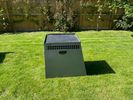
Thread upload9 viewsImage uploaded in new thread
|
|

Thread upload5 viewsImage uploaded in new thread
|
|
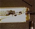
Actuator box underside 63 viewsUsed a clove hitch with plastic zip tie with 1/8" Kevlar rope
|
|
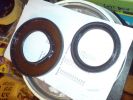
Transfer box seals111 views
|
|
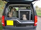
Willow in Trans K986 views
|
|
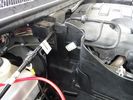
63 viewsThe spot where the isolator box goes had this small white clip. It looked like it was meant to hold something....so I removed it.
|
|

62 viewsYou can see how the spot to mount the control box has the long flat section to the left - so I mounted the box upside down to allow the 2-sided tape to stick to this bit.
|
|
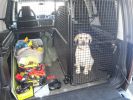
Jake and his new dog box60 views
|
|
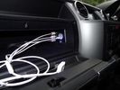
iPod connectors16 viewsAux video and Audio inputs (for nav screen) and usb charge point in upper glovebox
|
|
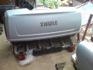
Thule backbox143 views
|
|
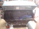
Thule back box139 views
|
|
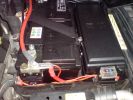
Main battery and accessory fuse box215 views
|
|

D3 Hawkeye Boxed45 views
|
|
89 viewsRear of car, note control? box just behind and above rear diff
|
|
Cool box463 views
|
|

70 L water + 3x20 L fuel + alu box442 views
|
|

Toolbox and ropes425 views
|
|
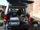
Expensive table?198 viewsOne of the better, if little, publicised advantages of the Disco3 is the split tailgate. Here its serving as the desk area at an outdoor event I was doing sound for. Rain was threatening so the amps got slung back inside rather than sat on the floor, other stuff was either in closed boxes or had to take its chances....
|
|
auto gearbox leak96 views
|
|
Retrocamera in funzione47 viewsVisione della parte posteriore in un box
|
|
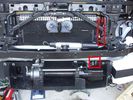
Installed winch with hydraulic hoses178 viewsThe hydraulic hoses are stiff, so I had to run them up the side of the radiator (can just see inside red boxes) to near the top of the radiator, then back down inside the engine compartment, then underneath the engine (behind the radiator) to the D4's power steering rack, where the hoses become metal. This hose routing may not be possible if the fuel-burning heater is in place (we don't have those in Aust and the space allowed room for my hands to bend and run the hoses without kinking).
|
|
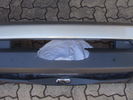
Front bumper with cutout for winch rope entry117 viewsBumper was initially cut "too small" with a low speed hand-held jig saw. It was then progressively filed to about the right size. Finally a very sharp box cutter was used to provide a smooth edge to the cut. This cutout is hidden behind the licence plate.
|
|
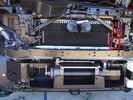
Installed winch with electrical solenoid connections163 viewsI routed the electrical supply (2 small wires) up the side of the radiator. You can see the unconnected wires inside the red boxes. I ended up connecting them on the radiator diagonal strut with cable ties. They are out of the way for any deep water transits there.
|
|
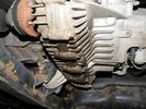
Transfer Box Oil Leak 19.6.201056 views
|
|

AVIC F500BT-USB129 viewsUSB-Connector in glove box.
|
|
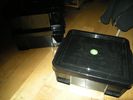
R U Boxes17 views
|
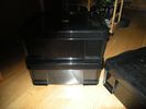
|
R U Boxes18 views
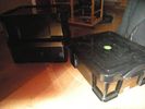
|
|
R U Boxes17 views
|
|
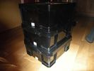
R U Boxes15 views
|
|
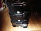
Really Useful Boxes17 views
|
|
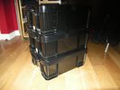
R U Boxes17 views
|
|
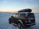
Box tail17 views
|
|
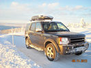
Box front17 views
|
|
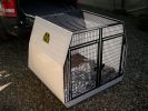
Lintran custom D3 dog box220 views
|
|
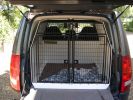
Lintran Dog Box. Snug fit!240 views
|
|
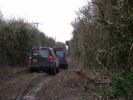
Bobbycrispbox Sunday160 views
|
|
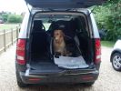
DogBag291 viewsMedium size DogBag from www.roofbox.co.uk
|
|
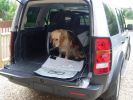
DogBag291 viewsMedium size DogBag from www.roofbox.co.uk
|
|
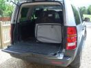
DogBag268 viewsMedium size DogBag from www.roofbox.co.uk
|
|
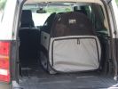
DogBag283 viewsMedium size DogBag from www.roofbox.co.uk
|
|
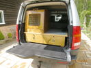
New Fishing Box87 views
|
|

Auto gearbox22 views
|
|

Reversing sensor blackbox controller412 views
|
|
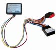
the blackbox to make it play during drive96 viewsplaced on the left side of the radio
|
|
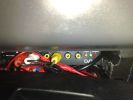
dvb in cupholder104 views
|
|
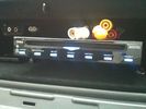
DVD Player63 viewsVeba DVD Player fitted into top glove box, AUX in for connection of Ipod, Games COnsoles etc. Remote control with sensor mounted by rear view mirror.
|
|

Thread upload15 viewsImage uploaded in new thread
|
|
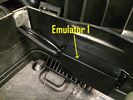
55 views
|
|
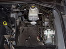
Spare Battery Bay with unknown box near the dipstick38 views
|
|
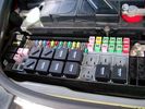
Eng compartment fuse box16 viewsEng compartment fuse box
|
|

Thread upload2 viewsImage uploaded in thread 201220
|
|
Thread upload2 viewsImage uploaded in thread 201220
|
|
Thread upload1 viewsImage uploaded in thread 201220
|
|

Thread upload2 viewsImage uploaded in thread 201220
|
|
Thread upload2 viewsImage uploaded in thread 201220
|
|
Thread upload5 viewsImage uploaded in thread 201220
|
|

55 viewsfbh fuse location in engine bay fuse box
|
|
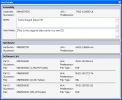
Flash File Loader Pop up Info Box76 views
|
|
Thread upload14 viewsImage uploaded in new thread
|
|
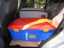
Was hoping to use these boxes, but can\'t stack securely so looks like I\'ll be getting some wolf crates afterall133 views
|
|

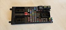
Ford Sounder 4L1Z-15K864 A that I installed.12 viewsThis is the Ford sounder, part number 4L1Z-15K864 that I purchased and installed in lieu of the official Land Rover sounder. Note the part number is what is printed on the box (and also my invoice) but the part number on the sounder body is a bit different. I think a new box/invoice related part number is created each time the price of a part is changed. Regardless the Ford sounder was about half the cost of the Land Rover part and sounds the same as the removed factory buzzer.
|
|
Thread upload0 viewsImage uploaded in new thread
|
|

Thread upload0 viewsImage uploaded in new thread
|
|
51 views
|
|
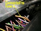
44 views
|
|
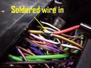
45 views
|
|
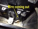
47 views
|
|
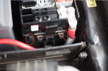
13 views
|
|
Thread upload4 viewsImage uploaded in new thread
|
|

Thread upload4 viewsImage uploaded in thread 40682
|
|
Thread upload12 viewsImage uploaded in new thread
|
|

Thread upload21 viewsImage uploaded in thread 172761
|
|

Thread upload1 viewsImage uploaded in thread 43242
|
|
24 views
|
|

Thread upload9 viewsImage uploaded in thread 189220
|
|

Thread upload8 viewsImage uploaded in thread 192528
|
|

Thread upload4 viewsImage uploaded in thread 197477
|
|

Thread upload4 viewsImage uploaded in thread 205879
|
|
Thread upload29 viewsImage uploaded in thread 115335
|
|
Thread upload13 viewsImage uploaded in thread 165268
|
|
10 views
|
|
Thread upload7 viewsImage uploaded in thread 197477
|
|

Thread upload8 viewsImage uploaded in thread 197477
|
|

Thread upload5 viewsImage uploaded in thread 206858
|
|
Thread upload7 viewsImage uploaded in thread 205879
|
|
Thread upload4 viewsImage uploaded in thread 206858
|
|
39 viewsmanual gearbox oil at 72k the transfer box oil look the same as this
|
|

55 views
|
|
96 views
|
|

Thread upload30 viewsImage uploaded in thread 103996
|
|

Thread upload5 viewsImage uploaded in new thread
|
|
Thread upload7 viewsImage uploaded in new thread
|
|

Thread upload12 viewsImage uploaded in thread 146455
|
|

Thread upload28 viewsImage uploaded in thread 103996
|
|

Thread upload11 viewsImage uploaded in thread 146455
|
|

Thread upload14 viewsImage uploaded in thread 146455
|
|

Thread upload7 viewsImage uploaded in new thread
|
|
Thread upload6 viewsImage uploaded in thread 154160
|
|
Thread upload2 viewsImage uploaded in thread 188863
|
|
Thread upload2 viewsImage uploaded in new thread
|
|

Thread upload17 viewsImage uploaded in thread 159832
|
|

Fix stiff gear selector or jumping out of drive into neutral32 viewsThis is a document culled from a topic about a simple fix to teh gearbox selector lever that fixes a problem with jumping out of drive into neutral.
I made the document to give to my local independent and thought it might be useful for others.
Thanks to disco_mikey, EdF and Robbie from the original post whose information and photos made this possible (I take no credit for anything here apart from errors).
|
|

Fix stiff gear selector or jumping out of drive into neutral17 viewsUpdated 19 Dec 2012
This is a document culled from a topic about a simple fix to the gearbox selector lever that fixes a problem with jumping out of drive into neutral.
I made the document to give to my local independent and thought it might be useful for others.
Thanks to disco_mikey, EdF and Robbie from the original post whose information and photos made this possible (I take no credit for anything here apart from errors).
Updated after I did this fix on my own car.
|
|

Thread upload35 viewsImage uploaded in thread 76678
|
|

Thread upload31 viewsImage uploaded in thread 76678
|
|

Thread upload9 viewsImage uploaded in thread 79211
|
|

Thread upload11 viewsImage uploaded in new thread
|
|
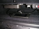
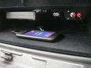
Glovebox 1142 viewsLocated D&P box on underside of glovebox, same as LR iPod/MP3 box
|
|
Glovebox 2132 views
|
|

Thread upload6 viewsImage uploaded in new thread
|
|
Thread upload4 viewsImage uploaded in new thread
|
|

Thread upload14 viewsImage uploaded in new thread
|
|

Thread upload14 viewsImage uploaded in new thread
|
|
Thread upload15 viewsImage uploaded in new thread
|
|

Thread upload5 viewsImage uploaded in new thread
|
|

Thread upload4 viewsImage uploaded in new thread
|
|
Thread upload2 viewsImage uploaded in new thread
|
|
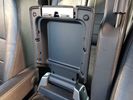
Thread upload0 viewsImage uploaded in thread 184194
|
|
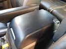
Thread upload0 viewsImage uploaded in thread 184194
|
|

90 viewsRed FBH WBUS wire behind fusebox CJB
C2411 C2412
|
|
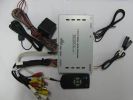
GVIF box83 views
|
|
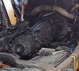
Thread upload9 viewsImage uploaded in thread 198243
|
|

45 viewsHinge inside LR/Thule roof box
|
|
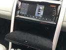
Thread upload7 viewsImage uploaded in new thread
|
|
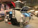
Thread upload4 viewsImage uploaded in new thread
|
|
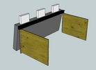
Thread upload14 viewsImage uploaded in thread 106371
|
|
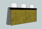
Thread upload16 viewsImage uploaded in thread 106371
|
|

Thread upload15 viewsImage uploaded in thread 106371
|
|

Thread upload8 viewsImage uploaded in thread 126243
|
|
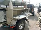
Thread upload9 viewsImage uploaded in thread 126243
|
|

Thread upload11 viewsImage uploaded in thread 132482
|
|
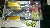
Underside137 viewsThe underside of the inside box. Resistors are 6 ohms with a power rating of 50w, don't be tempted to get the lower power rating.
|
|
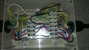
Topside124 viewsWiring from the top, one additional earth added to the internal box after the picture was taken.
|
|
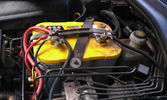
The auxiliary battery21 viewsThe auxiliary battery in the bay.
As the wiring diagram I made shows, there's a wire leading to the fuse box in the rear. (is going through the key-switch)
The second one is going to the fog lights. The smaller cables which should be connected to the head-lights, are connected to the battery.
The third one is going to the compressor (via a switch) (sits before the key-switch)
A fourth one is going to the CB and battery check display (sits before the key-switch)
|
|

Close up - key in place16 viewsThe key placed and turned in order to turn the switch on.
Everything connected to the fuse box in the rear and the fog lights on the roofrack will work now.
|
|

An extra 12V outlet16 viewsOn the passenger side, I added a 12V outlet which is fed through the fuse box in the rear and adds as such an outlet for whatever charger we don't want to have lingering around around the central console.
The USB charging outlets are visible as well :)
|
|
Fuse box in the rear15 viewsI installed the fuse box in the rear. Since I do have a 5-seater, there's plenty of space in the booth beneath the 2nd cover, which rests behind the second row seats.
|
|
transfer box leak - apparently not529 viewsleak discovered today crap
|
|
Junction box24 views
|
|
Box picture 20 views
|
|

Roofbox part17 views
|
|
Box contents15 views
|
|

Good as New CTJ3000G jack adaptor 51 viewsCouple of scratches from being in my toolbox. Never used on the jack
|
|

Boxing Day bash '1320 views
|
|

Consumer box RCBO26 views
|
|
Topbox113 views
|
|
Topbox210 views
|
|
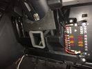
Aux battery fuse box17 viewsMy install of a fuse box.
|
|

Iphone box6 views
|
|

Fridge Boxed15 views
|
|

Aux battery fuse box19 viewsClose up of fuse box
|
|
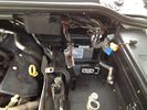
Battery box34 views
|
|

Transfer box oil22 views
|
|

963 viewsRipping off the cheap carpet reveales the galvanised steel box with sharp edges that has been fixed in with 4 ton of silicon.
|
|

901 viewsripping out the tackky metal box that is part of the Irish commercial conversion
|
|
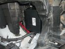
1633 viewspicture showing the location of the "Lodar" radio winch remote control box.
|
|
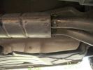
New stainless mid box540 views
|
|

The finnished box, With bit's in769 views
|
|
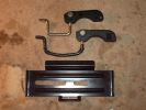
Roof box fixings379 viewsTop original with new one in middle!
Had to make the hole to the left of the plate longer to fit new brackets, it was the same size!
|
|
Roof box fixing new ones!316 viewsnow wide enough for LR roof bars!
|
|
Roof box fixing original313 views
|
|
Picture of the engine compartment fuse panel5778 viewsEngine compartment fuse panel located near the battery. This is where F3E, (5 amp), F26E, (20 amp), Fuseable link 10E, (60 amp) and Relay 7E, the now upgraded 70 amp air compressor motor relay, part number YWB500220, (E is for Engine compartment fuse box), are all located. Fuse F35P, (5 amp), is inside the Passenger compartment behind the lower glove box door.
To keep the suspension from going down to the stops when driving, (or parked), it appears that it is only really necessary to remove F26E to depower the exhaust valve and generally keep all the valve block solenoid valves in a closed position trapping whatever air is within the air springs. F3E gets its power thru F26E, so when F26E is removed, the F3E circuit is automatically de-powered. F35P is more interesting in that battery power goes thru the ignition switch and F35P and then into the air suspension control unit. Apparently however, if F26E is removed, removing the F35P is not needed even when the engine is running.
With all fuses still in, if you have a problem, in practice, ideally, the compressor still works and will raise the 3 to an appropriate height. If so, one can then shut the engine off and allow the computers to go to sleep and then you remove the fuse(s). In actual practice, it seems that one need only pull the F26E fuse and can do so with the engine running. All the same, one might consider that the 3 is first a mobile computer, and secondly a 4x4. Computers prefer to go to sleep before the plug is pulled on them, however given that F26E circuit is always alive, then the computer never sleeps. With the fuse(s) pulled, and if you are still up, you can now be a 4x4 instead of a low rider. The whole purpose of the fuse pulling exercise is to depower the one and only system exhaust valve that is physically located within the compressor unit, (to keep it from opening), and secondarily to keep closed the four air spring solenoids within the block valves. This also shuts the air compressor down and stops the air compressor from making air even if the compressor is still good. That is why you initially need the fuse(s) in to allow the compressor to make air if it can.
|
|
300tdi auto box conversion47 views
|
|
Speaker (above glove box) and Handset for HF Radio153 views
|
|
3 Gomo boxes fit in each drawer219 views
|
|
110 viewsview of wires inside dash (from where plug was removed). I ran them through the pre-existing slit in the top of the glove box to wiring loom connector.
|
|

98 viewsPlug removed from left hand side of dash to locate wires from clove box
|
|

105 viewsextended wire running from glove box to loom connector.
|
|
101 viewsexisting slot in top side of glove box used.
|
|
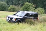
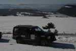
bobbycrisbox in a bog at Rockingham, July 2009328 viewsCALENDAR 2010
|
|

2009 CALENDAR ENTRY419 viewsBodsy / bobbycrispboxmobile on the Crosiere
|
|
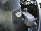
Bottom of airbox, showing one-way valve and locating lug176 views
|
|

Auto Gearbox29 views
|
|
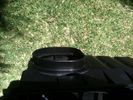
Half way finished cutting aibox inlet with Dremel - as it was too large to fit the 83mm flexible hose onto it.164 views
|
|
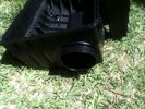
Airbox showing inner inlet tube poking through189 views
|
|
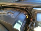
Looking down at jubilee clamp holding flexible hose to airbox inlet.184 views
|
|
2009 CALENDAR ENTRY385 viewsbobbycrispboxmobile on the Croisiere
|
|

drilling holes into cubby box for AV connection panel54 viewswork in progress
|
|
4GA Power Cable15 viewsFrom fuse box on aux battery - along channel.
|
|

AV connector for RSE61 viewsdecided to install AV connector in Cubby box between seats (no fridge in my car) so I can store an iPod hidden in there to provide media for Rear Seat Entertainment
|
|

glovebox alien65 views
|
|

Arse end with new chrome tails, dog box and DVD if you look closer468 views
|
|
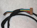
GSM box end of the cable harness75 viewsGreen, blue & orange wires not connected
|
|

Junction box for all wires51 views
|
|
toolbox37 views
|
|
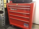
toolbox 143 views
|
|
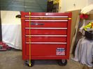
Toolbox37 views
|
|

TH Bury AD 9060 - box50 views
|
|

Contents of MSV2 box34 views
|
|

Picking sheet in MSV2 box25 views
|
|
gearbox oil cooler248 viewsThis is whats inside your radiator as you transmission oil cooler!
|
|
new transfer box28 views
|
|
new gearbox22 views
|
|

new gearbox bell housing19 views
|
|

Under Drivers Seat - Connector box (being opened)44 views
|
|

Under Drivers Seat - Connector box40 views
|
|
| 622 files on 2 page(s) |
 |
1 |  |
|