| Last additions - navydevildoc's Gallery |
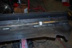
190 viewsA closer look at the drainage channels.06 Feb 2010
|
|
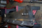
182 viewsAnother shot of the right slider. The center support channel has drainage channels welded in that match the locations of the drain holes on the sill frame.06 Feb 2010
|
|
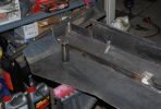
190 viewsGetting closer to the finished product. The steel tube in the middle reaches up to the body mounts on the frame.06 Feb 2010
|
|
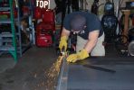
163 viewsUsing the plasma cutter to trim up slider plates06 Feb 2010
|
|
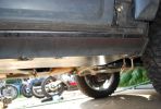
194 viewsRight front showing rough fit of the slider06 Feb 2010
|
|
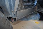
183 viewsRough fit showing the rear end with the support channel and slider plates.06 Feb 2010
|
|
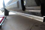
189 viewsSupport Channel bolted up to the door sill06 Feb 2010
|
|
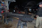
172 viewsFirst stab at the bottom plate welded to the support channel.06 Feb 2010
|
|
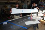
161 viewsPattern for the right side slider. Almost ready to cut!06 Feb 2010
|
|

200 views25 Jun 2007
|
|

151 viewsAnother day at o\'briens10 May 2007
|
|
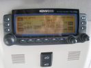
461 viewsCompleted install of control panel.01 May 2007
|
|
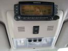
388 viewsCompleted Install of Control Panel. Wiring goes up into headliner, over curtain airbag on left hand side, and down the B pillar.01 May 2007
|
|
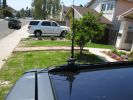
348 viewsAntenna Mount01 May 2007
|
|
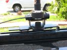
327 viewsAntenna mount.01 May 2007
|
|
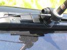
335 viewsHere is the antenna mount on the roof rack. The black aluminum bar is custom made to hold the antenna mount.01 May 2007
|
|
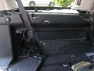
372 viewsHere is the left rear trim panel removed. GTR proved useful in the removal process! The cubby box snaps on to the top of the panel.01 May 2007
|
|
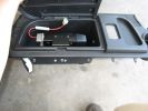
414 viewsHere is the left rear cubby box with the TM-D700A bolted inside. I also drilled a hole in the bottom of the cubby for antenna, GPS, and power wiring, and a hole in the front for control, microphone, data, and audio cabling.01 May 2007
|
|
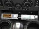
355 viewsCompleted install, again with aluminum bar and 3M velcro.28 Apr 2007
|
|
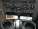
307 viewsCompleted install. I used a bar of aluminum bar with 3M industrial velcro to hold the controllers.28 Apr 2007
|
|
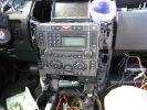
329 viewsInstallation slowly proceeding. You can see the controller cables inserted into the notch I made with a dremel.28 Apr 2007
|
|
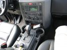
255 viewsAlmost completed install. Just the controllers need mounting.28 Apr 2007
|
|
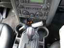
246 viewsAlmost done. All the trim is in, but the controllers are not yet mounted.28 Apr 2007
|
|
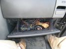
292 viewsThe rats nest of cabling that needs to be tamed.28 Apr 2007
|
|
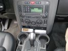
259 viewsCompleted install with both receivers working.28 Apr 2007
|
|
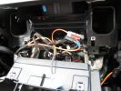
278 viewsClose up of the cavity for the Nav screen. Here you can see the XM Satellite receiver antenna cable snaking across. It\'s the thin wire not bundled to anything. In the lower corner you can also see the power cable going to the glove box.28 Apr 2007
|
|
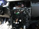
278 viewsA mess of cables. You can see the HD Radio antenna adapter coming out into the slot for the IHU. You can also see, if you look very closely, the original diversity antenna connector plugged into another adapter to go down to the HD radio unit.28 Apr 2007
|
|
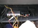
248 viewsThe two installed modules with preliminary wiring for testing.28 Apr 2007
|
|
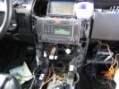
257 viewsSystem testing. Nothing caught fire, which is a success in my book! Just know that the rover gets very angry when all of those control panels are disconnected.28 Apr 2007
|
|
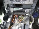
255 viewsThe console mostly re-assembled. You can see the dremel notch I made for the control cables, as well as the slack in the power and audio cables.28 Apr 2007
|
|
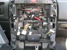
261 viewsPicture of the center console minus IHU and Climate Control. Turns out there is very little room behind there, which is really a pain in the ass.28 Apr 2007
|
|
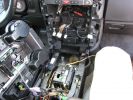
246 viewsProceeding with console removal.28 Apr 2007
|
|
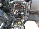
253 viewsProceeding with the console removal.28 Apr 2007
|
|
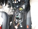
286 viewsPicture of the floor console removed. The wiring moving along from the bottom of the picture forward is power from the rear power socket, and audio from the aux port.28 Apr 2007
|
|
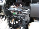
280 viewsHere is the center console with the support pulled away. You can see the wiring for the HD and XM radios working their way through the console and over to the lower glove box. 28 Apr 2007
|
|
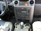
211 viewsThe start. Yes, the cupholders are dirty... get over it!28 Apr 2007
|
|
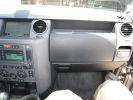
216 viewsThe start. I plan to place all the electronics into the lower glove box.28 Apr 2007
|
|
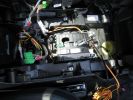
220 viewsAnother shot of the floor console.28 Apr 2007
|
|
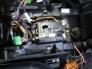
219 viewsThe inner workings of the floor console. You can see the inline fuse holder on the left, which then connects to the chill box connector.28 Apr 2007
|
|
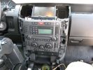
233 viewsConsole Trim Removed, as well as the top of the floor console.28 Apr 2007
|
|

150 viewsMe out at Goldstone25 Apr 2007
|
|
|
|
|
|
|